Trouble with Sensebender gateway initialisation
-
Hi all,
I have been using MySensors for 3 years now. I built my origional serial GW using a UNO, and utilising soft signing. All worked well for a few months at a time, but I ran into issues, as detailed here.I bought, built and installed a Sensebender gateway, and all was well for a while, However I seemingly killed it when I upped the MY_RFM69_TX_POWER_DBM (13) up to "20", in an effort to solve a troublesome node often not getting messages that were sent to it.
I reverted to my home built UNO gateway, and ordered a new Sensebender Gateway, which has sat on a shelf for several months. I decided to assemble and make use of the "new" sensebender gateway today, fitting a new RFM69HW to the board.
I have wiped it, personalised it, and uploaded the same GW sketch as previously used.It doesn't work! this is the output, which I put through the log parser, which also doesn't work?
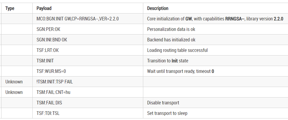
0;255;hu;0;hu;3 MCO:BGN:INIT GW,CP=RRNGSA--,VER=2.2.0
0;255;hu;0;hu;3 SGN:PER:OK
0;255;hu;0;hu;3 SGN:INI:BND OK
0;255;hu;0;hu;3 TSF:LRT:OK
0;255;hu;0;hu;3 TSM:INIT
0;255;hu;0;hu;3 TSF:WUR:MS=0
0;255;hu;0;hu;3 !TSM:INIT:TSP FAIL
0;255;hu;0;hu;3 TSM:FAIL:CNT=hu
0;255;hu;0;hu;3 TSM:FAIL:DIS
0;255;hu;0;hu;3 TSF:TDI:TSL
I reflowed the RFM69 Pads, incase there was a crack or otherwise faulty joint, to no avail, I joined SWC2, and that stopped at eprom.
for completeness, here is the GW sketch. Arduino IDE is 1.8.13
Suggestions?
/** * The MySensors Arduino library handles the wireless radio link and protocol * between your home built sensors/actuators and HA controller of choice. * The sensors forms a self healing radio network with optional repeaters. Each * repeater and gateway builds a routing tables in EEPROM which keeps track of the * network topology allowing messages to be routed to nodes. * * Created by Henrik Ekblad <henrik.ekblad@mysensors.org> * Copyright (C) 2013-2015 Sensnology AB * Full contributor list: https://github.com/mysensors/Arduino/graphs/contributors * * Documentation: http://www.mysensors.org * Support Forum: http://forum.mysensors.org * * This program is free software; you can redistribute it and/or * modify it under the terms of the GNU General Public License * version 2 as published by the Free Software Foundation. * ******************************* * * DESCRIPTION * The ArduinoGateway prints data received from sensors on the serial link. * The gateway accepts input on seral which will be sent out on radio network. * * This GW code is designed for Sensebender GateWay / (Arduino Zero variant) * * Wire connections (OPTIONAL): * - Inclusion button should be connected to SW2 * * LEDs on board (default assignments): * - Orange: USB RX/TX - Blink when receiving / transmitting on USB CDC device * - Yellow: RX - Blink fast on radio message recieved. In inclusion mode will blink fast only on presentation recieved * - Green : TX - Blink fast on radio message transmitted. In inclusion mode will blink slowly * - Red : ERR - Fast blink on error during transmission error or recieve crc error * - Blue : free - (use with LED_BLUE macro) * */ #define SKETCH_VERSION "0.2" // Enable debug prints to serial monitor #define MY_DEBUG #define MY_DEBUG_VERBOSE_SIGNING #define MY_SIGNING_ATSHA204 //#define MY_SIGNING_SOFT //#define MY_SIGNING_SOFT_RANDOMSEED_PIN 7 //#define MY_SIGNING_WEAK_SECURITY // only for debug // Enable and select radio type attached #define MY_RADIO_RFM69 #define MY_RFM69_FREQUENCY RFM69_433MHZ // Set your frequency here #define MY_RFM69_TX_POWER_DBM (14) //#define MY_RFM69_MAX_POWER_LEVEL_DBM (14) // max. TX power 10dBm = 10mW #define MY_IS_RFM69HW // Omit if your RFM is not "H" //#define MY_RF69_IRQ_PIN 2 //#define MY_RF69_IRQ_NUM MY_RF69_IRQ_PIN //#define MY_RFM69_CS_PIN 10 // NSS. Use MY_RF69_SPI_CS for older versions (before 2.2.0) //#define MY_TRANSPORT_WAIT_READY_MS 25000 //#define MY_RFM69_ENABLE_ENCRYPTION //#define MY_RFM69_NETWORKID 100 // Default is 100 in lib. Uncomment it and set your preferred network id if needed //#define MY_SPLASH_SCREEN_DISABLED // Enable serial gateway #define MY_GATEWAY_SERIAL // Define a lower baud rate for Arduino's running on 8 MHz (Arduino Pro Mini 3.3V & SenseBender) #if F_CPU == 8000000L #define MY_BAUD_RATE 38400 #endif // Enable inclusion mode //#define MY_INCLUSION_MODE_FEATURE // Enable Inclusion mode button on gateway #//define MY_INCLUSION_BUTTON_FEATURE // Inverses behavior of inclusion button (if using external pullup) //#define MY_INCLUSION_BUTTON_EXTERNAL_PULLUP // Set inclusion mode duration (in seconds) //#define MY_INCLUSION_MODE_DURATION 60 // Digital pin used for inclusion mode button //#define MY_INCLUSION_MODE_BUTTON_PIN 3 // Set blinking period #define MY_DEFAULT_LED_BLINK_PERIOD 300 // Inverses the behavior of leds //#define MY_WITH_LEDS_BLINKING_INVERSE // Flash leds on rx/tx/err // Uncomment to override default HW configurations //#define MY_DEFAULT_ERR_LED_PIN 4 // Error led pin //#define MY_DEFAULT_RX_LED_PIN 6 // Receive led pin //#define MY_DEFAULT_TX_LED_PIN 5 // the PCB, on board LED #include <MySensors.h> #include <SD.h> //#include <drivers/ATSHA204/ATSHA204.cpp> Sd2Card card; #define EEPROM_VERIFICATION_ADDRESS 0x01 static uint8_t num_of_leds = 5; static uint8_t leds[] = {LED_BLUE, LED_RED, LED_GREEN, LED_YELLOW, LED_ORANGE}; void setup() { // Setup locally attached sensors } void presentation() { // Present locally attached sensors } void loop() { // Send locally attached sensor data here } void preHwInit() { pinMode(MY_SWC1, INPUT_PULLUP); pinMode(MY_SWC2, INPUT_PULLUP); if (digitalRead(MY_SWC1) && digitalRead(MY_SWC2)) { return; } uint8_t tests = 0; for (int i=0; i< num_of_leds; i++) { pinMode(leds[i], OUTPUT); } uint8_t led_state = 0; if (digitalRead(MY_SWC1)) { while (!Serial) { digitalWrite(LED_BLUE, led_state); led_state ^= 0x01; delay(500); } // Wait for USB to be connected, before spewing out data. } digitalWrite(LED_BLUE, LOW); if (Serial) { Serial.println("Sensebender GateWay test routine"); Serial.print("Mysensors core version : "); Serial.println(MYSENSORS_LIBRARY_VERSION); Serial.print("GateWay sketch version : "); Serial.println(SKETCH_VERSION); Serial.println("----------------------------------"); Serial.println(); } if (testSha204()) { digitalWrite(LED_GREEN, HIGH); tests++; } if (testSDCard()) { digitalWrite(LED_YELLOW, HIGH); tests++; } if (testEEProm()) { digitalWrite(LED_ORANGE, HIGH); tests++; } if (testAnalog()) { digitalWrite(LED_BLUE, HIGH); tests++; } if (tests == 4) { while(1) { for (int i=0; i<num_of_leds; i++) { digitalWrite(leds[i], HIGH); delay(200); digitalWrite(leds[i], LOW); } } } else { while (1) { digitalWrite(LED_RED, HIGH); delay(200); digitalWrite(LED_RED, LOW); delay(200); } } } bool testSha204() { uint8_t rx_buffer[SHA204_RSP_SIZE_MAX]; uint8_t ret_code; if (Serial) { Serial.print("- > SHA204 "); } atsha204_init(MY_SIGNING_ATSHA204_PIN); ret_code = atsha204_wakeup(rx_buffer); if (ret_code == SHA204_SUCCESS) { ret_code = atsha204_getSerialNumber(rx_buffer); if (ret_code != SHA204_SUCCESS) { if (Serial) { Serial.println(F("Failed to obtain device serial number. Response: ")); } Serial.println(ret_code, HEX); } else { if (Serial) { Serial.print(F("Ok (serial : ")); for (int i=0; i<9; i++) { if (rx_buffer[i] < 0x10) { Serial.print('0'); // Because Serial.print does not 0-pad HEX } Serial.print(rx_buffer[i], HEX); } Serial.println(")"); } return true; } } else { if (Serial) { Serial.println(F("Failed to wakeup SHA204")); } } return false; } bool testSDCard() { if (Serial) { Serial.print("- > SD CARD "); } if (!card.init(SPI_HALF_SPEED, MY_SDCARD_CS)) { if (Serial) { Serial.println("SD CARD did not initialize!"); } } else { if (Serial) { Serial.print("SD Card initialized correct! - "); Serial.print("type detected : "); switch(card.type()) { case SD_CARD_TYPE_SD1: Serial.println("SD1"); break; case SD_CARD_TYPE_SD2: Serial.println("SD2"); break; case SD_CARD_TYPE_SDHC: Serial.println("SDHC"); break; default: Serial.println("Unknown"); } } return true; } return false; } bool testEEProm() { uint8_t eeprom_d1, eeprom_d2; SerialUSB.print(" -> EEPROM "); eeprom_d1 = hwReadConfig(EEPROM_VERIFICATION_ADDRESS); delay(500); eeprom_d1 = ~eeprom_d1; // invert the bits hwWriteConfig(EEPROM_VERIFICATION_ADDRESS, eeprom_d1); delay(500); eeprom_d2 = hwReadConfig(EEPROM_VERIFICATION_ADDRESS); if (eeprom_d1 == eeprom_d2) { SerialUSB.println("PASSED"); hwWriteConfig(EEPROM_VERIFICATION_ADDRESS, ~eeprom_d1); return true; } SerialUSB.println("FAILED!"); return false; } bool testAnalog() { int bat_detect = analogRead(MY_BAT_DETECT); Serial.print("-> analog : "); Serial.print(bat_detect); if (bat_detect < 400 || bat_detect > 650) { Serial.println(" Failed"); return false; } Serial.println(" Passed"); return true; } -
-
Hi,
Solder sucked off all I could, have re-soldered, cannot remove the RFM69. Output still the same.
0;255;hu;0;hu;3 MCO:BGN:INIT GW,CP=RRNGSA--,VER=2.2.0

0;255;hu;0;hu;3 SGN:PER:OK

0;255;hu;0;hu;3 SGN:INI:BND OK

0;255;hu;0;hu;3 TSF:LRT:OK

0;255;hu;0;hu;3 TSM:INIT

0;255;hu;0;hu;3 TSF:WUR:MS=0

0;255;hu;0;hu;3 !TSM:INIT:TSP FAIL

0;255;hu;0;hu;3 TSM:FAIL:CNT=hu

0;255;hu;0;hu;3 TSM:FAIL:DIS

0;255;hu;0;hu;3 TSF:TDI:TSL

0;255;hu;0;hu;3 TSM:FAIL:RE-INIT

0;255;hu;0;hu;3 TSM:INIT

0;255;hu;0;hu;3 !TSM:INIT:TSP FAIL

0;255;hu;0;hu;3 TSM:FAIL:CNT=hu

0;255;hu;0;hu;3 TSM:FAIL:DIS

0;255;hu;0;hu;3 TSF:TDI:TSL

0;255;hu;0;hu;3 TSM:FAIL:RE-INIT

0;255;hu;0;hu;3 TSM:INIT

0;255;hu;0;hu;3 !TSM:INIT:TSP FAIL

0;255;hu;0;hu;3 TSM:FAIL:CNT=hu

0;255;hu;0;hu;3 TSM:FAIL:DIS

0;255;hu;0;hu;3 TSF:TDI:TSL

0;255;hu;0;hu;3 TSM:FAIL:RE-INIT

0;255;hu;0;hu;3 TSM:INIT

0;255;hu;0;hu;3 !TSM:INIT:TSP FAIL

0;255;hu;0;hu;3 TSM:FAIL:CNT=hu

0;255;hu;0;hu;3 TSM:FAIL:DIS

0;255;hu;0;hu;3 TSF:TDI:TSL

0;255;hu;0;hu;3 TSM:FAIL:RE-INIT

0;255;hu;0;hu;3 TSM:INIT

0;255;hu;0;hu;3 !TSM:INIT:TSP FAIL

0;255;hu;0;hu;3 TSM:FAIL:CNT=hu

0;255;hu;0;hu;3 TSM:FAIL:DIS

0;255;hu;0;hu;3 TSF:TDI:TSL

0;255;hu;0;hu;3 TSM:FAIL:RE-INIT

0;255;hu;0;hu;3 TSM:INIT

0;255;hu;0;hu;3 !TSM:INIT:TSP FAIL

0;255;hu;0;hu;3 TSM:FAIL:CNT=hu

0;255;hu;0;hu;3 TSM:FAIL:DIS

0;255;hu;0;hu;3 TSF:TDI:TSL

0;255;hu;0;hu;3 TSM:FAIL:RE-INIT

0;255;hu;0;hu;3 TSM:INIT

0;255;hu;0;hu;3 !TSM:INIT:TSP FAIL

0;255;hu;0;hu;3 TSM:FAIL:CNT=hu

0;255;hu;0;hu;3 TSM:FAIL:DIS

0;255;hu;0;hu;3 TSF:TDI:TSL
Other than the RFM69 and the antenna, there is nothing else for me to fit / configure is there?
-
Hi All,
And the hits keep coming......
Ok, So I have messed up my Arduino IDE / compiler somehow.
I thought I would roll back the board definition, as the board I have is several months old.
That didn't work, insofar as i now get the following error, upon compiling for the Sensebender GW board******************************************************************************* **Arduino: 1.8.13 (Windows 10), TD: 1.53, Board: "Sensebender Gateway" In file included from D:\NWCloudDrive\Home Automation\Arduino\libraries\MySensors/hal/architecture/SAMD/MyHwSAMD.cpp:20:0, from D:\NWCloudDrive\Home Automation\Arduino\libraries\MySensors/MySensors.h:67, from N:\Home Automation\Arduino\MySensors\testing_node\testing_node.ino:29: D:\NWCloudDrive\Home Automation\Arduino\libraries\MySensors/hal/architecture/SAMD/MyHwSAMD.h:26:10: fatal error: avr/dtostrf.h: No such file or directory #include <avr/dtostrf.h> ^~~~~~~~~~~~~~~ compilation terminated. exit status 1 Error compiling for board Sensebender Gateway.** *********************************************************************************I re installed upto 1.0.6 but the error remains.
I have looked in backups and googled as to where the file should be, to no avail! (i've found where it should be, but it doesn't exist in that location in my backups).Help if you can Please, I realise this may not be the best place for this particular issue, but I thought I should avoid starting a new thread if I can.
SOLUTION to this Compiler issue WAS FOUND HERE
basically Roll back SAMD board definition to 1.8.9
The basic issue of the non functional Radio still remains.
-
The log output is still the same : the transport is not found.
I would verify and measure the connections of the radio module to the ATSAMD21 µProcessor.
See schematic at https://www.mysensors.org/hardware/sensebender-gateway, search MysensorsGW.pdf
If these are all correct, a faulty RFM69? -
The log output is still the same : the transport is not found.
I would verify and measure the connections of the radio module to the ATSAMD21 µProcessor.
See schematic at https://www.mysensors.org/hardware/sensebender-gateway, search MysensorsGW.pdf
If these are all correct, a faulty RFM69?@evb
Hi,Have checked continuity, all connected, including DIO 5 (not sure what that's used for)
RFM69 is powered, at the pads of the sub board, (3.293V)
If the RFM69HW is faulty< I don't think I can safely remove it, thats what ultimately did for the first Sensebender GW board, I destroyed the pads trying to remove the RFM69.Any Suggestions as to how to attempt. I don't have a hot air type tool for SMD components, Just a soldering Iron. Buying one would cost the same as buying a new Sensebender, without the knowledge that replacing the RFM69 is the actual answer.
-
Hi All,
So I have re-visited the onboard diag sketch, and ran it, the prog hangs at the eeprom testing, as soon as it makes an attempt to read
eeprom_d1 = hwReadConfig(EEPROM_VERIFICATION_ADDRESS);
I have added some additional Serial outputs to see where it was failing, but it fails at the first hurdle.
This might indicate to me that the board is indeed faulty.Sketch output
Sensebender GateWay test routine
Mysensors core version : 2.2.0
GateWay sketch version : 0.2
----------------------------------

- > SHA204 Ok (serial : 012329BE97196D83EE)
- > SD CARD SD Card initialized correct! - type detected : SDHC
 -> EEPROM
Sensebender Sketch
/** * The MySensors Arduino library handles the wireless radio link and protocol * between your home built sensors/actuators and HA controller of choice. * The sensors forms a self healing radio network with optional repeaters. Each * repeater and gateway builds a routing tables in EEPROM which keeps track of the * network topology allowing messages to be routed to nodes. * * Created by Henrik Ekblad <henrik.ekblad@mysensors.org> * Copyright (C) 2013-2015 Sensnology AB * Full contributor list: https://github.com/mysensors/Arduino/graphs/contributors * * Documentation: http://www.mysensors.org * Support Forum: http://forum.mysensors.org * * This program is free software; you can redistribute it and/or * modify it under the terms of the GNU General Public License * version 2 as published by the Free Software Foundation. * ******************************* * * DESCRIPTION * The ArduinoGateway prints data received from sensors on the serial link. * The gateway accepts input on seral which will be sent out on radio network. * * This GW code is designed for Sensebender GateWay / (Arduino Zero variant) * * Wire connections (OPTIONAL): * - Inclusion button should be connected to SW2 * * LEDs on board (default assignments): * - Orange: USB RX/TX - Blink when receiving / transmitting on USB CDC device * - Yellow: RX - Blink fast on radio message recieved. In inclusion mode will blink fast only on presentation recieved * - Green : TX - Blink fast on radio message transmitted. In inclusion mode will blink slowly * - Red : ERR - Fast blink on error during transmission error or recieve crc error * - Blue : free - (use with LED_BLUE macro) * */ #define SKETCH_VERSION "0.2" // Enable debug prints to serial monitor #define MY_DEBUG // Enable and select radio type attached //#define MY_RADIO_NRF24 //#define MY_RADIO_NRF5_ESB #define MY_RADIO_RFM69 #define MY_RFM69_FREQUENCY RFM69_433MHZ // Set your frequency here #define MY_RFM69_TX_POWER_DBM (13) //#define MY_RFM69_MAX_POWER_LEVEL_DBM (13) // max. TX power 10dBm = 10mW #define MY_IS_RFM69HW // Omit if your RFM is not "H" //#define MY_RADIO_RFM95 // Set LOW transmit power level as default, if you have an amplified NRF-module and // power your radio separately with a good regulator you can turn up PA level. #define MY_RF24_PA_LEVEL RF24_PA_HIGH // Enable serial gateway #define MY_GATEWAY_SERIAL // Define a lower baud rate for Arduino's running on 8 MHz (Arduino Pro Mini 3.3V & SenseBender) #if F_CPU == 8000000L #define MY_BAUD_RATE 38400 #endif // Enable inclusion mode #define MY_INCLUSION_MODE_FEATURE // Enable Inclusion mode button on gateway #define MY_INCLUSION_BUTTON_FEATURE // Inverses behavior of inclusion button (if using external pullup) //#define MY_INCLUSION_BUTTON_EXTERNAL_PULLUP // Set inclusion mode duration (in seconds) #define MY_INCLUSION_MODE_DURATION 60 // Digital pin used for inclusion mode button //#define MY_INCLUSION_MODE_BUTTON_PIN 3 // Set blinking period #define MY_DEFAULT_LED_BLINK_PERIOD 300 // Inverses the behavior of leds //#define MY_WITH_LEDS_BLINKING_INVERSE // Flash leds on rx/tx/err // Uncomment to override default HW configurations //#define MY_DEFAULT_ERR_LED_PIN 4 // Error led pin //#define MY_DEFAULT_RX_LED_PIN 6 // Receive led pin //#define MY_DEFAULT_TX_LED_PIN 5 // the PCB, on board LED #include <MySensors.h> #include <SD.h> #include <drivers/ATSHA204/ATSHA204.cpp> Sd2Card card; #define EEPROM_VERIFICATION_ADDRESS 0x01 static uint8_t num_of_leds = 5; static uint8_t leds[] = {LED_BLUE, LED_RED, LED_GREEN, LED_YELLOW, LED_ORANGE}; void setup() { // Setup locally attached sensors } void presentation() { // Present locally attached sensors } void loop() { // Send locally attached sensor data here } void preHwInit() { pinMode(MY_SWC1, INPUT_PULLUP); pinMode(MY_SWC2, INPUT_PULLUP); if (digitalRead(MY_SWC1) && digitalRead(MY_SWC2)) { return; } uint8_t tests = 0; for (int i=0; i< num_of_leds; i++) { pinMode(leds[i], OUTPUT); } uint8_t led_state = 0; if (digitalRead(MY_SWC1)) { while (!Serial) { digitalWrite(LED_BLUE, led_state); led_state ^= 0x01; delay(500); } // Wait for USB to be connected, before spewing out data. } digitalWrite(LED_BLUE, LOW); if (Serial) { Serial.println("Sensebender GateWay test routine"); Serial.print("Mysensors core version : "); Serial.println(MYSENSORS_LIBRARY_VERSION); Serial.print("GateWay sketch version : "); Serial.println(SKETCH_VERSION); Serial.println("----------------------------------"); Serial.println(); } if (testSha204()) { digitalWrite(LED_GREEN, HIGH); tests++; } if (testSDCard()) { digitalWrite(LED_YELLOW, HIGH); tests++; } if (testEEProm()) { digitalWrite(LED_ORANGE, HIGH); tests++; } if (testAnalog()) { digitalWrite(LED_BLUE, HIGH); tests++; } if (tests == 4) { while(1) { for (int i=0; i<num_of_leds; i++) { digitalWrite(leds[i], HIGH); delay(200); digitalWrite(leds[i], LOW); } } } else { while (1) { digitalWrite(LED_RED, HIGH); delay(200); digitalWrite(LED_RED, LOW); delay(200); } } } bool testSha204() { uint8_t rx_buffer[SHA204_RSP_SIZE_MAX]; uint8_t ret_code; if (Serial) { Serial.print("- > SHA204 "); } atsha204_init(MY_SIGNING_ATSHA204_PIN); ret_code = atsha204_wakeup(rx_buffer); if (ret_code == SHA204_SUCCESS) { ret_code = atsha204_getSerialNumber(rx_buffer); if (ret_code != SHA204_SUCCESS) { if (Serial) { Serial.println(F("Failed to obtain device serial number. Response: ")); } Serial.println(ret_code, HEX); } else { if (Serial) { Serial.print(F("Ok (serial : ")); for (int i=0; i<9; i++) { if (rx_buffer[i] < 0x10) { Serial.print('0'); // Because Serial.print does not 0-pad HEX } Serial.print(rx_buffer[i], HEX); } Serial.println(")"); } return true; } } else { if (Serial) { Serial.println(F("Failed to wakeup SHA204")); } } return false; } bool testSDCard() { if (Serial) { Serial.print("- > SD CARD "); } if (!card.init(SPI_HALF_SPEED, MY_SDCARD_CS)) { if (Serial) { Serial.println("SD CARD did not initialize!"); } } else { if (Serial) { Serial.print("SD Card initialized correct! - "); Serial.print("type detected : "); switch(card.type()) { case SD_CARD_TYPE_SD1: Serial.println("SD1"); break; case SD_CARD_TYPE_SD2: Serial.println("SD2"); break; case SD_CARD_TYPE_SDHC: Serial.println("SDHC"); break; default: Serial.println("Unknown"); } } return true; } return false; } bool testEEProm() { uint8_t eeprom_d1, eeprom_d2; SerialUSB.print(" -> EEPROM "); eeprom_d1 = hwReadConfig(EEPROM_VERIFICATION_ADDRESS); delay(500); SerialUSB.print("EEPROM Read Address ");SerialUSB.print(EEPROM_VERIFICATION_ADDRESS); SerialUSB.print(" EEPROM Read Value ");SerialUSB.println(eeprom_d1); eeprom_d1 = ~eeprom_d1; // invert the bits hwWriteConfig(EEPROM_VERIFICATION_ADDRESS, eeprom_d1); SerialUSB.print("EEPROM Write Address ");SerialUSB.print(EEPROM_VERIFICATION_ADDRESS); SerialUSB.print(" EEPROM Write Value ");SerialUSB.println(eeprom_d1); delay(500); eeprom_d2 = hwReadConfig(EEPROM_VERIFICATION_ADDRESS); SerialUSB.print("EEPROM RE- READ Address ");SerialUSB.print(EEPROM_VERIFICATION_ADDRESS); SerialUSB.print(" EEPROM RE-READ Value ");SerialUSB.println(eeprom_d2); if (eeprom_d1 == eeprom_d2) { SerialUSB.println("PASSED"); hwWriteConfig(EEPROM_VERIFICATION_ADDRESS, ~eeprom_d1); return true; } SerialUSB.println("FAILED!"); return false; } bool testAnalog() { int bat_detect = analogRead(MY_BAT_DETECT); Serial.print("-> analog : "); Serial.print(bat_detect); if (bat_detect < 400 || bat_detect > 650) { Serial.println(" Failed"); return false; } Serial.println(" Passed"); return true; } -
Hi,
Well something not right.
I went looking for the functions used for the eeprom,
found it in "MyHWSAMD.cpp"
Modified the code temporarily to see what if anything was happeningCode mod
uint8_t hwReadConfig(int adr)
{
	SerialUSB.print("EEPROM Read Address MyHwsamd.cpp = ");SerialUSB.println(adr);
	SerialUSB.print("EEPROM Read VALUE MyHwsamd.cpp = ");SerialUSB.print(eep.read(adr));
	return eep.read(adr);
}
which gives this output in the test prog
Mysensors core version : 2.2.0
GateWay sketch version : 0.2
----------------------------------

- > SHA204 Ok (serial : 012329BE97196D83EE)
- > SD CARD SD Card initialized correct! - type detected : SDHC
 -> EEPROM EEPROM Read Address MyHwsamd.cpp = 1
EEPROM Read VALUE MyHwsamd.cpp =
So without further digging, I am stuffed as there seems to not be anything being read back from the eeprom, either that or the code is stuffed (unlikely)
If people think the Sensebender is faulty, Ill see if I can get a replacement under warranty?
Can anyone / is anyone able to duplicate the test prog situation with the eeprom fail ?
-
Do you mean to remove the RFM69HW chip or the complete RFM69HW sub-board?
Removing the sub-board should be possible with a normal soldering iron and a desoldering pump sucker tool.
On internet you will find plenty of information how to desolder components, even on youtube where you can see it...
What for type of soldering iron do you have?If the provided tests are not passing, there is something wrong.
Can you post some photo's of your board and solderings? -
Do you mean to remove the RFM69HW chip or the complete RFM69HW sub-board?
Removing the sub-board should be possible with a normal soldering iron and a desoldering pump sucker tool.
On internet you will find plenty of information how to desolder components, even on youtube where you can see it...
What for type of soldering iron do you have?If the provided tests are not passing, there is something wrong.
Can you post some photo's of your board and solderings?@evb
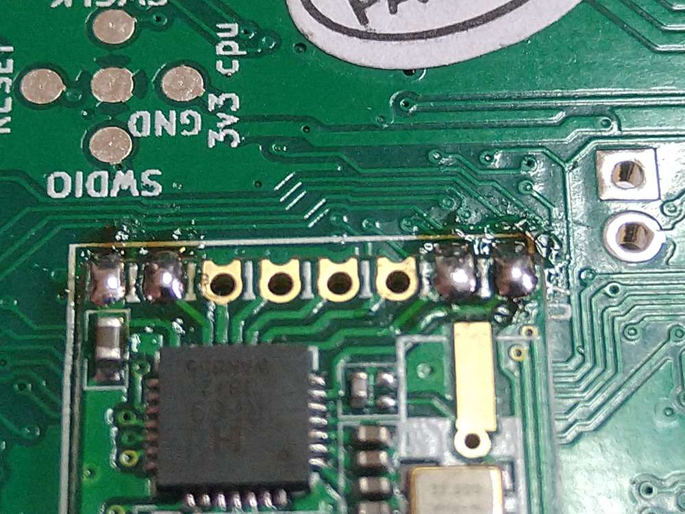
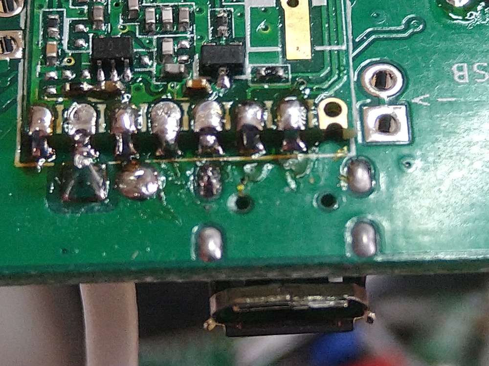
Hi,Sorry for the confusion, I mean the entire RFM69HW sub board.
The difficulty is that by the nature of the edge connections, and the "holes" the solder flows under the "pads" as well as to the sides, and given that there is no "flex" in the board, it isn't possible (at least on my attempts) to stop any pad from re-attaching to the main board. As I say, I had a go with the previous one, and damaged it beyond repair, removing the RFM69HW.
My solder station is a cheap temperature controllable one, with a circa 1mm round tip, solder sucking off the majority of the solder isn't able to freeup a pad. I have removed the solder and re-soldered this chip three times now, to ensure good connections, which is why you will see loads of excess flux, which I haven't bothered to clean off as yet, given the project isn't finished / working. I have tried getting the smallest, circa 0.5mm jewellers screwdriver under the edge of the RFM69 board, whilst heating the nearest corner pad, without success.Photos below, as I say a bit of a mess with the excess flux, the continuity has however been proven to all the MCU pins.
The excess solder is due to the fact I attached wires to each pad, for the continuity checking, being as it is that the MCU chip is on the other side of the PCB.The on sketch testing is definitely failing as mentioned above.
Hello! It looks like you're interested in this conversation, but you don't have an account yet.
Getting fed up of having to scroll through the same posts each visit? When you register for an account, you'll always come back to exactly where you were before, and choose to be notified of new replies (either via email, or push notification). You'll also be able to save bookmarks and upvote posts to show your appreciation to other community members.
With your input, this post could be even better 💗
Register Login