GUIDE - NRF5 / NRF51 / NRF52 for beginners
-
I just got my first NRF5 running. I'll note how I got it working in case any of you guys still have troubles:
Setup
- OS: Windows 10
- Programmer: STM32 Blue Pill with the Black Magic Probe firmware
- NRF5: EByte E73-TBB dev board with a E73-2G4M0S1B (NRF52832)
- Environment: PlatformIO
Instructions
Load the Black Magic Probe firmware with
stlinkas the probe host onto Blue Pill. You can follow this guide.Connect your new BMP to the NRF52 module:
BMP NRF52 Serial Port 3V3 3V3 GND GND A5 SWDCLK GDB Server B14 SWDIO GBD Server A2 RXI UART A3 TXO UART Note: A2 and A3 are not required for programming. This is how you'd wire up the BMP for "classic" serial debugging. You can use the BMP both for programming and serial communication - no need for a second FTDI module.
Using the GNU Arm Embedded Toolchain, run
arm-none-eabi-gdbin a console and enter the following commands to unlock the NRF52:target extended-remote BMP_GDB_SERVER_PORT mon swdp_scan attach N // N = number of "Nordic nRF52 Access Port" if there are several mon erase_mass detachFrom the two serial ports the BMP provides, you want to use the GDB Server for
BMP_GDB_SERVER_PORTabove. If Windows only provides generic names for both ("USB Serial Device" or something), the one with the lower number should (usually) be the right choice. If not, try the other one.Windows users also must prefix the port with
\\.\if the number is double-digit, e.g.\\.\COM13.Now you can start uploading sketches the usual way. Here's my minimal PlatformIO config:
[env:nrf52_dk]
platform = nordicnrf52
board = nrf52_dk
board_build.variant = generic
framework = arduino
upload_protocol = blackmagic
lib_deps =
	548 ; MySensors
And a minimal test sketch for MySensors:
#include <Arduino.h>

#define LED 17

#define MY_RADIO_RF24
#define MY_RADIO_NRF5_ESB
#define MY_NODE_ID 182

#define SKETCH_NAME "NRF52 Test"
#define SKETCH_VERSION "0.1"

#include <MySensors.h>

#define CHILD_ID 1
MyMessage msg(CHILD_ID, V_VAR1);

void presentation()
{
  sendSketchInfo(SKETCH_NAME, SKETCH_VERSION);
  present(CHILD_ID, S_CUSTOM);
}

void setup()
{
  pinMode(LED, OUTPUT);
}

void loop()
{
  static uint8_t num;
  send(msg.set(num));
  ++num;

  digitalWrite(LED, HIGH);
  wait(5000);
  digitalWrite(LED, LOW);
  wait(5000);
}
Works like a charm so far! Now, if you please excuse me, I have a whole new microprocessor family to explore. Fun times!
@BearWithBeard said in GUIDE - NRF5 / NRF51 / NRF52 for beginners:
I just got my first NRF5 running. I'll note how I got it working in case any of you guys still have troubles:
Setup
- OS: Windows 10
- Programmer: STM32 Blue Pill with the Black Magic Probe firmware
- NRF5: EByte E73-TBB dev board with a E73-2G4M0S1B (NRF52832)
- Environment: PlatformIO
Instructions
Load the Black Magic Probe firmware with
stlinkas the probe host onto Blue Pill. You can follow this guide.Connect your new BMP to the NRF52 module:
BMP NRF52 Serial Port 3V3 3V3 GND GND A5 SWDCLK GDB Server B14 SWDIO GBD Server A2 TX UART A3 RX UART Note: A2 and A3 are not required for programming. This is how you'd wire up the BMP for "classic" serial debugging. You can use the BMP both for programming and serial communication - no need for a second FTDI module.
Using the GNU Arm Embedded Toolchain, run
arm-none-eabi-gdbin a console and enter the following commands to unlock the NRF52:target extended-remote BMP_GDB_SERVER_PORT mon swdp_scan attach N // N = number of "Nordic nRF52 Access Port" if there are several mon erase_mass detachFrom the two serial ports the BMP provides, you want to use the GDB Server for
BMP_GDB_SERVER_PORTabove. If Windows only provides generic names for both ("USB Serial Device" or something), the one with the lower number should (usually) be the right choice. If not, try the other one.Windows users also must prefix the port with
\\.\if the number is double-digit, e.g.\\.\COM13.Now you can start uploading sketches the usual way. Here's my minimal PlatformIO config:
[env:nrf52_dk]
platform = nordicnrf52
board = nrf52_dk
board_build.variant = generic
framework = arduino
upload_protocol = blackmagic
lib_deps =
	548 ; MySensors
And a minimal test sketch for MySensors:
#include <Arduino.h>

#define LED 17

#define MY_RADIO_RF24
#define MY_RADIO_NRF5_ESB
#define MY_NODE_ID 182

#define SKETCH_NAME "NRF52 Test"
#define SKETCH_VERSION "0.1"

#include <MySensors.h>

#define CHILD_ID 1
MyMessage msg(CHILD_ID, V_VAR1);

void presentation()
{
  sendSketchInfo(SKETCH_NAME, SKETCH_VERSION);
  present(CHILD_ID, S_CUSTOM);
}

void setup()
{
  pinMode(LED, OUTPUT);
}

void loop()
{
  static uint8_t num;
  send(msg.set(num));
  ++num;

  digitalWrite(LED, HIGH);
  wait(5000);
  digitalWrite(LED, LOW);
  wait(5000);
}
Works like a charm so far! Now, if you please excuse me, I have a whole new microprocessor family to explore. Fun times!
For the life of me i cant figure out if im making the BlackMagic properly. I'm moving the boot0 jumper to 1, flashing the 8kb maple (usb flash) DFU file using the st-link application on windows.
I move the jumper back to 0, and connect using the micro usb, and i can flash code normally using arudino IDE using the STM32duino bootloader (and if i do so, i see the device communication on a new COM port).
From there i cant get anything from these guides to work. the windows STM "flash demonstrator" app doesnt recognize the device, and i dont have a linux machine available at the moment for the dfu-util (and Ubuntu shell on windows wont recognize the usb device). When i try to flash the blackmagic.bin starting at 0x08002000 using the ST-link software it shows it succeeded, but when i return the jumper to 0 and reset the device, this is what i get:
The 2 new COM ports appear (COM12,COM13), but i cant seem to flash anything successfully.
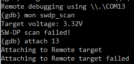
I've installed the GNU arm toolchain for windows and tried "target extended-remote \.\COM13" (12 just gets stuck on nothing), and i get:
-
@idanronen , I am not an expert but did manage to accomplish what you are doing about a year ago. I can tell you that you are supposed to get two com ports from BMP. Also, where your screen shot says "SW-DP scan failed" means BMP cannot find any 'targets' on the nrf52. You should get back something that looks like this from the scan:
Available Targets:
No. Att Driver
1 ARM Cortex-M
2 Nordic nRF52 Access PortI performed this operation on ~10 nrf52832 and only one failed the scan. I never found out how to solve it.
Also, your use of the attach command is incorrect. You appear to be trying to attach the com port 13. If the swdp_scan had worked corrrectly, you would then attach the target that shows up in the scan. In my example output, it would be "attach 2" - the nRF52 Access Port.
That adds what I know, hope it helps a bit.
-
Hello, I'm using MySensors for some years now and after using the NRF24 and recently the RFM69 I want to explore the NRF5 platform.
My idea is to use a NRF52840 as gateway, and NRF52832 as nodes. So I am making a list so I can get started, but was wondering what else I should order besides the NRF5's?
I read a programmer is required, for example. What is your experience or advice for this? A ST-link or J-link? Could you share your experiences?
Thanks
Rik -
Hello, I'm using MySensors for some years now and after using the NRF24 and recently the RFM69 I want to explore the NRF5 platform.
My idea is to use a NRF52840 as gateway, and NRF52832 as nodes. So I am making a list so I can get started, but was wondering what else I should order besides the NRF5's?
I read a programmer is required, for example. What is your experience or advice for this? A ST-link or J-link? Could you share your experiences?
Thanks
Rik@electrik I believe NRF52832 and 51822 are the only supported NRF modules at this time. Some people have experimented and modified dependent libraries to get NRF52840 to work with MySensors but I'm not sure it's completely working and definitely wouldn't start there.
Personally, I like using the Ebyte NRF24 PA+LNA modules for my gateways and repeaters and use the NRF5 modules for end nodes.
I'm not even sure you can use NRF5 as a radio for a gateway, if so it might only work as a serial gateway.
As for additional items, I bought a jlink clone after having trouble unlocking ebyte modules with a STLink. Then my jlink clone caused issues (old firmware, not updatable) so I ended up buying a real JLink-edu.
Other things worth noting: there are a surprising number of hardware bugs with the NRF chips that mostly result in higher power consumption. General advice would be to stay away from NRF51822. EBYTE modules have been consistently reliable, high quality.
-
@electrik I believe NRF52832 and 51822 are the only supported NRF modules at this time. Some people have experimented and modified dependent libraries to get NRF52840 to work with MySensors but I'm not sure it's completely working and definitely wouldn't start there.
Personally, I like using the Ebyte NRF24 PA+LNA modules for my gateways and repeaters and use the NRF5 modules for end nodes.
I'm not even sure you can use NRF5 as a radio for a gateway, if so it might only work as a serial gateway.
As for additional items, I bought a jlink clone after having trouble unlocking ebyte modules with a STLink. Then my jlink clone caused issues (old firmware, not updatable) so I ended up buying a real JLink-edu.
Other things worth noting: there are a surprising number of hardware bugs with the NRF chips that mostly result in higher power consumption. General advice would be to stay away from NRF51822. EBYTE modules have been consistently reliable, high quality.
@ncollins It is possible to use NRF51822 for gateways with serial. I am using it for many months now. We need USB to serial adapter.
Also, I do not use JLink or ST-Link for flashing the NRF51 chips. I use raspberry pi with OpenOCD.
OpenOCD setup can be overwhelming (it was for me) but I have been able to make it work and replicate for a while now. If someone needs inputs, I am happy to help. Ask here or reach out to me on discord @ Puneit#2433For the very reason you stated - hardware bugs in NR51 chips leading to high power-consumption - they make compact repeater nodes / powered nodes with repeaters.
-
@monte Could you please share the custom sleep function?
@Puneit-Thukral you can start looking from here https://forum.mysensors.org/post/92044
-
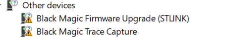
Is it possible to use such a ready made device, and reprogram it with a mysensors sketch?
@electrik yes. You will need an SWD programmer, J-link, ST-link or black magic probe will do. But the thing, you've linked isn't NRF5 device. So if you are asking about exactly that device, then answer is no. Only Nordic bluetooth devices are supported by mysensors. The one you've linked uses TI chip.
-
@electrik yes. You will need an SWD programmer, J-link, ST-link or black magic probe will do. But the thing, you've linked isn't NRF5 device. So if you are asking about exactly that device, then answer is no. Only Nordic bluetooth devices are supported by mysensors. The one you've linked uses TI chip.
@monte Thanks. I didn't notice it was not a Nordic one. So if I take such module, I just have to figure out the pins to program and it can be re-used.
Did you or someone else ever tried this? -
@monte Thanks. I didn't notice it was not a Nordic one. So if I take such module, I just have to figure out the pins to program and it can be re-used.
Did you or someone else ever tried this?Hi @electrik
You can program these ibeacons to work with MySensors.
I reprogrammed one by soldering some wires to a jlink adapter. Not elegant, but it worked.
Some type of push pin setup would be good if you are going to actually use these modules.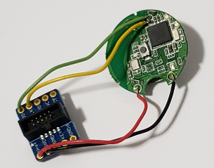
The version I got had only a button on the board, and no way to easily add any other sensors, so they weren't very useful. It would be interesting to try the ones with the temperature and acceleromator.
-
I am using a generic nRF52 dev board with the Arduino nRF52 core. I am trying to get a sample BLE service to display, but it cannot find it on my BLE scanner. After I couldn't get that to work, I decided to make the code even simpler. Since the dev board that I am using has a serial USB out I thought I would just check if I could get a "Hello World!" to the serial monitor... After flashing the soft device, I still couldn't get any output on my serial monitor.
Open On-Chip Debugger 0.10.0-dev-00254-g696fc0a (2016-04-10-10:13)
Licensed under GNU GPL v2
For bug reports, read
	http://openocd.org/doc/doxygen/bugs.html
debug_level: 0
0x4000
adapter speed: 10000 kHz
nrf52.cpu: target state: halted
target halted due to debug-request, current mode: Thread
xPSR: 0x61000000 pc: 0x0001b08e msp: 0x20001188
nrf52.cpu: target state: halted
target halted due to debug-request, current mode: Thread
xPSR: 0x01000000 pc: 0xfffffffe msp: 0xfffffffc
** Programming Started **
auto erase enabled
nrf52.cpu: target state: halted
target halted due to breakpoint, current mode: Thread
xPSR: 0x61000000 pc: 0x2000001e msp: 0xfffffffc
wrote 114688 bytes from file C:\Users\Admin\Documents\ArduinoData\packages\sandeepmistry\hardware\nRF5\0.7.0/cores/nRF5/SDK/components/softdevice/s132/hex/s132_nrf52_2.0.1_softdevice.hex in 2.559271s (43.762 KiB/s)
** Programming Finished **
** Verify Started **
nrf52.cpu: target state: halted
target halted due to breakpoint, current mode: Thread
xPSR: 0x61000000 pc: 0x2000002e msp: 0xfffffffc
nrf52.cpu: target state: halted
target halted due to breakpoint, current mode: Thread
xPSR: 0x61000000 pc: 0x2000002e msp: 0xfffffffc
verified 110636 bytes in 0.372659s (289.924 KiB/s)
** Verified OK **
** Resetting Target **
shutdown command invoked
I am using OpenOCD and an ST-Link v2 to upload my code and it looks like it is uploading successfully. Here is the output when I try to flash the S132 soft device:
void setup() {
  Serial.begin(9600);
  Serial.println("Starting...");

}

void loop() {
  Serial.println("Hello World!");
  delay(1000);

}
I also tried running this code with the MySensors library:
#define MY_RADIO_NRF5_ESB
#include <MySensors.h>

void setup() {
  Serial.begin(9600);
  Serial.println("Starting");
}

void loop() {
  Serial.println("Hello World!");
  delay(3000);
}
And got this error:
In file included from C:\Users\Admin\Documents\ArduinoData\packages\sandeepmistry\hardware\nRF5\0.7.0\cores\nRF5/Arduino.h:5:0, from sketch\MyBoardNRF5.ino.cpp:1: c:\users\admin\documents\arduinodata\packages\sandeepmistry\tools\gcc-arm-none-eabi\5_2-2015q4\lib\gcc\arm-none-eabi\5.2.1\include\stdint.h:9:26: fatal error: stdint.h: No such file or directory compilation terminated. exit status 1 Error compiling for board MyBoardNRF5 nRF52832. Error while flashing SoftDevice. java.io.FileNotFoundException: C:\Users\Admin\Documents\ArduinoData\packages\MySensors\hardware\nRF5\0.3.0\softdevices.txt (The system cannot find the file specified) -
I am using a generic nRF52 dev board with the Arduino nRF52 core. I am trying to get a sample BLE service to display, but it cannot find it on my BLE scanner. After I couldn't get that to work, I decided to make the code even simpler. Since the dev board that I am using has a serial USB out I thought I would just check if I could get a "Hello World!" to the serial monitor... After flashing the soft device, I still couldn't get any output on my serial monitor.
Open On-Chip Debugger 0.10.0-dev-00254-g696fc0a (2016-04-10-10:13)
Licensed under GNU GPL v2
For bug reports, read
	http://openocd.org/doc/doxygen/bugs.html
debug_level: 0
0x4000
adapter speed: 10000 kHz
nrf52.cpu: target state: halted
target halted due to debug-request, current mode: Thread
xPSR: 0x61000000 pc: 0x0001b08e msp: 0x20001188
nrf52.cpu: target state: halted
target halted due to debug-request, current mode: Thread
xPSR: 0x01000000 pc: 0xfffffffe msp: 0xfffffffc
** Programming Started **
auto erase enabled
nrf52.cpu: target state: halted
target halted due to breakpoint, current mode: Thread
xPSR: 0x61000000 pc: 0x2000001e msp: 0xfffffffc
wrote 114688 bytes from file C:\Users\Admin\Documents\ArduinoData\packages\sandeepmistry\hardware\nRF5\0.7.0/cores/nRF5/SDK/components/softdevice/s132/hex/s132_nrf52_2.0.1_softdevice.hex in 2.559271s (43.762 KiB/s)
** Programming Finished **
** Verify Started **
nrf52.cpu: target state: halted
target halted due to breakpoint, current mode: Thread
xPSR: 0x61000000 pc: 0x2000002e msp: 0xfffffffc
nrf52.cpu: target state: halted
target halted due to breakpoint, current mode: Thread
xPSR: 0x61000000 pc: 0x2000002e msp: 0xfffffffc
verified 110636 bytes in 0.372659s (289.924 KiB/s)
** Verified OK **
** Resetting Target **
shutdown command invoked
I am using OpenOCD and an ST-Link v2 to upload my code and it looks like it is uploading successfully. Here is the output when I try to flash the S132 soft device:
void setup() {
  Serial.begin(9600);
  Serial.println("Starting...");

}

void loop() {
  Serial.println("Hello World!");
  delay(1000);

}
I also tried running this code with the MySensors library:
#define MY_RADIO_NRF5_ESB
#include <MySensors.h>

void setup() {
  Serial.begin(9600);
  Serial.println("Starting");
}

void loop() {
  Serial.println("Hello World!");
  delay(3000);
}
And got this error:
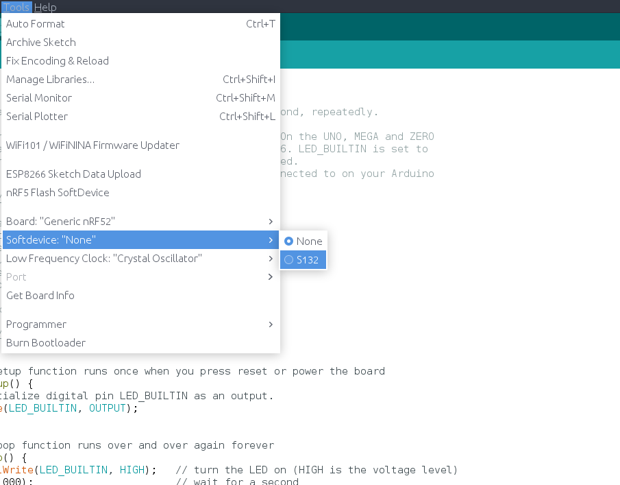
In file included from C:\Users\Admin\Documents\ArduinoData\packages\sandeepmistry\hardware\nRF5\0.7.0\cores\nRF5/Arduino.h:5:0, from sketch\MyBoardNRF5.ino.cpp:1: c:\users\admin\documents\arduinodata\packages\sandeepmistry\tools\gcc-arm-none-eabi\5_2-2015q4\lib\gcc\arm-none-eabi\5.2.1\include\stdint.h:9:26: fatal error: stdint.h: No such file or directory compilation terminated. exit status 1 Error compiling for board MyBoardNRF5 nRF52832. Error while flashing SoftDevice. java.io.FileNotFoundException: C:\Users\Admin\Documents\ArduinoData\packages\MySensors\hardware\nRF5\0.3.0\softdevices.txt (The system cannot find the file specified)@abelson first you have to flash SD and then chose softdevice in board options and flash your sketch.
It seems that you are lacking softdevice binary. It seems that your version of sandeepmistry's NRF5 core is pretty outdated, you have 0.3 version when surrent version is 0.7. No wonder that links to softdevice binaries are broken insoftdevices.txt. Try updating core to the latest version and/or downloading softevice binary from nordic's site yourself. -
@abelson first you have to flash SD and then chose softdevice in board options and flash your sketch.
It seems that you are lacking softdevice binary. It seems that your version of sandeepmistry's NRF5 core is pretty outdated, you have 0.3 version when surrent version is 0.7. No wonder that links to softdevice binaries are broken insoftdevices.txt. Try updating core to the latest version and/or downloading softevice binary from nordic's site yourself. -
@monte that makes sense. Do you know what options I have to do to flash the sketch after I flash the soft device? If I get the above output that I posted, does that mean that the soft device flashed successfully?
-
@BearWithBeard said in GUIDE - NRF5 / NRF51 / NRF52 for beginners:
I just got my first NRF5 running. I'll note how I got it working in case any of you guys still have troubles:
Setup
- OS: Windows 10
- Programmer: STM32 Blue Pill with the Black Magic Probe firmware
- NRF5: EByte E73-TBB dev board with a E73-2G4M0S1B (NRF52832)
- Environment: PlatformIO
Instructions
Load the Black Magic Probe firmware with
stlinkas the probe host onto Blue Pill. You can follow this guide.Connect your new BMP to the NRF52 module:
BMP NRF52 Serial Port 3V3 3V3 GND GND A5 SWDCLK GDB Server B14 SWDIO GBD Server A2 TX UART A3 RX UART Note: A2 and A3 are not required for programming. This is how you'd wire up the BMP for "classic" serial debugging. You can use the BMP both for programming and serial communication - no need for a second FTDI module.
Using the GNU Arm Embedded Toolchain, run
arm-none-eabi-gdbin a console and enter the following commands to unlock the NRF52:target extended-remote BMP_GDB_SERVER_PORT mon swdp_scan attach N // N = number of "Nordic nRF52 Access Port" if there are several mon erase_mass detachFrom the two serial ports the BMP provides, you want to use the GDB Server for
BMP_GDB_SERVER_PORTabove. If Windows only provides generic names for both ("USB Serial Device" or something), the one with the lower number should (usually) be the right choice. If not, try the other one.Windows users also must prefix the port with
\\.\if the number is double-digit, e.g.\\.\COM13.Now you can start uploading sketches the usual way. Here's my minimal PlatformIO config:
[env:nrf52_dk]
platform = nordicnrf52
board = nrf52_dk
board_build.variant = generic
framework = arduino
upload_protocol = blackmagic
lib_deps =
	548 ; MySensors
And a minimal test sketch for MySensors:
#include <Arduino.h>

#define LED 17

#define MY_RADIO_RF24
#define MY_RADIO_NRF5_ESB
#define MY_NODE_ID 182

#define SKETCH_NAME "NRF52 Test"
#define SKETCH_VERSION "0.1"

#include <MySensors.h>

#define CHILD_ID 1
MyMessage msg(CHILD_ID, V_VAR1);

void presentation()
{
  sendSketchInfo(SKETCH_NAME, SKETCH_VERSION);
  present(CHILD_ID, S_CUSTOM);
}

void setup()
{
  pinMode(LED, OUTPUT);
}

void loop()
{
  static uint8_t num;
  send(msg.set(num));
  ++num;

  digitalWrite(LED, HIGH);
  wait(5000);
  digitalWrite(LED, LOW);
  wait(5000);
}
Works like a charm so far! Now, if you please excuse me, I have a whole new microprocessor family to explore. Fun times!
For the life of me i cant figure out if im making the BlackMagic properly. I'm moving the boot0 jumper to 1, flashing the 8kb maple (usb flash) DFU file using the st-link application on windows.
I move the jumper back to 0, and connect using the micro usb, and i can flash code normally using arudino IDE using the STM32duino bootloader (and if i do so, i see the device communication on a new COM port).
From there i cant get anything from these guides to work. the windows STM "flash demonstrator" app doesnt recognize the device, and i dont have a linux machine available at the moment for the dfu-util (and Ubuntu shell on windows wont recognize the usb device). When i try to flash the blackmagic.bin starting at 0x08002000 using the ST-link software it shows it succeeded, but when i return the jumper to 0 and reset the device, this is what i get:
The 2 new COM ports appear (COM12,COM13), but i cant seem to flash anything successfully.
I've installed the GNU arm toolchain for windows and tried "target extended-remote \.\COM13" (12 just gets stuck on nothing), and i get:
-
I just got my first NRF5 running. I'll note how I got it working in case any of you guys still have troubles:
Setup
- OS: Windows 10
- Programmer: STM32 Blue Pill with the Black Magic Probe firmware
- NRF5: EByte E73-TBB dev board with a E73-2G4M0S1B (NRF52832)
- Environment: PlatformIO
Instructions
Load the Black Magic Probe firmware with
stlinkas the probe host onto Blue Pill. You can follow this guide.Connect your new BMP to the NRF52 module:
BMP NRF52 Serial Port 3V3 3V3 GND GND A5 SWDCLK GDB Server B14 SWDIO GBD Server A2 RXI UART A3 TXO UART Note: A2 and A3 are not required for programming. This is how you'd wire up the BMP for "classic" serial debugging. You can use the BMP both for programming and serial communication - no need for a second FTDI module.
Using the GNU Arm Embedded Toolchain, run
arm-none-eabi-gdbin a console and enter the following commands to unlock the NRF52:target extended-remote BMP_GDB_SERVER_PORT mon swdp_scan attach N // N = number of "Nordic nRF52 Access Port" if there are several mon erase_mass detachFrom the two serial ports the BMP provides, you want to use the GDB Server for
BMP_GDB_SERVER_PORTabove. If Windows only provides generic names for both ("USB Serial Device" or something), the one with the lower number should (usually) be the right choice. If not, try the other one.Windows users also must prefix the port with
\\.\if the number is double-digit, e.g.\\.\COM13.Now you can start uploading sketches the usual way. Here's my minimal PlatformIO config:
[env:nrf52_dk]
platform = nordicnrf52
board = nrf52_dk
board_build.variant = generic
framework = arduino
upload_protocol = blackmagic
lib_deps =
	548 ; MySensors
And a minimal test sketch for MySensors:
#include <Arduino.h>

#define LED 17

#define MY_RADIO_RF24
#define MY_RADIO_NRF5_ESB
#define MY_NODE_ID 182

#define SKETCH_NAME "NRF52 Test"
#define SKETCH_VERSION "0.1"

#include <MySensors.h>

#define CHILD_ID 1
MyMessage msg(CHILD_ID, V_VAR1);

void presentation()
{
  sendSketchInfo(SKETCH_NAME, SKETCH_VERSION);
  present(CHILD_ID, S_CUSTOM);
}

void setup()
{
  pinMode(LED, OUTPUT);
}

void loop()
{
  static uint8_t num;
  send(msg.set(num));
  ++num;

  digitalWrite(LED, HIGH);
  wait(5000);
  digitalWrite(LED, LOW);
  wait(5000);
}
Works like a charm so far! Now, if you please excuse me, I have a whole new microprocessor family to explore. Fun times!
@BearWithBeard
Great explanation, thanks!
On my windows 10 installation I had to run Zadig to make the programming from platformIO work. -
@BearWithBeard
What did you do to get the serial pins of the Ebyte development board configured correctly, when using the generic board variant in platformIO? I've copied MyBoardNRF5.cpp but this is not used it seems.
Also redefining the definitions from variant.h#define PIN_SERIAL_TX (11) #define PIN_SERIAL_RX (12)doesn't give serial output.
-
@BearWithBeard
What did you do to get the serial pins of the Ebyte development board configured correctly, when using the generic board variant in platformIO? I've copied MyBoardNRF5.cpp but this is not used it seems.
Also redefining the definitions from variant.h#define PIN_SERIAL_TX (11) #define PIN_SERIAL_RX (12)doesn't give serial output.
@electrik Yeah, I ran into that issue, too. Not sure if that's the proper way to solve it, but I add a custom board directory to the build flags in platformio.ini ...
build_flags =
	-I $PROJECT_DIR/boards/generic
... and copied the board variant files from
.platformio/packages/framework-arduinonordicnrf5/variants/Generic/toboards/generic/in my project folder. Changes made in here aren't ignored or overwritten by global PIO definitions.
Hello! It looks like you're interested in this conversation, but you don't have an account yet.
Getting fed up of having to scroll through the same posts each visit? When you register for an account, you'll always come back to exactly where you were before, and choose to be notified of new replies (either via email, or push notification). You'll also be able to save bookmarks and upvote posts to show your appreciation to other community members.
With your input, this post could be even better 💗
Register Login