nRF24Doctor

-
I do not follow you, to me we have 3.3V output regulation + 1,2V regulation margin which remains well under the 5V input of the regulator ( doesn't includes the 0,44v drop )
You're right. I knew there was something additional in the order of about that shunt voltage drop, but should have checked the layout to spark my memory a bit better. It is not the voltage drop of the shunt but if you use the 5V output from the nano board you may have to account for a reverse voltage protection diode that may be present (i.e. your 5V pin does not really 5V). That's why there is a jumper to directly supply from the Vin pin.
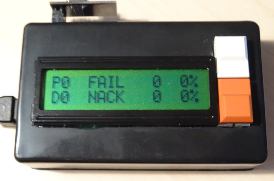
What is the FAIL and NACK % corresponding to
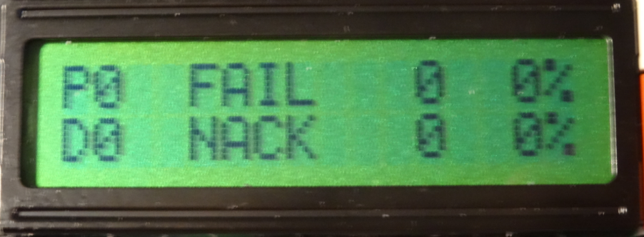
- As in the description with the first post it should report percentage of FAILED acknowledges for the first HOP transmit (if no repeater nodes are present, then the first HOP will be the Gateway). This is actually the confirmation at "nrf24 radio level" to report if the message was received by another radio.
- NACK : The gateway is requested an ACK message for every message the node transmits. So that means the round trip of the message from NODE-> GATEWAY -> NODE.
So it can be that you have no FAIL but a lot of NACK, which would mean that your test node can send out a message and was received by another radio, but never receives an ACK back for the transmitted message.
@Technovation
Many Thanks for your feedback, Yes we are fully in line, including the forward diode junction on the 5V.About the NACK and FAIL this is very clear to me for the absolute value but I was wondering for Percentage value.
I'm actually doing transmission benchmarks ( combining different radios, radio shields etc .... under exact same conditions ) over periods of 5 minutes with payloads of 2 and 100 Msg/s, and I thought the percentage shown corresponds to Nbr_of_fail / Total_Counter, but it is not and i assume percentage is rather calculated over last X.
This is a very very good tools, I really appreciate, OEM NRF24 module are not all the same some are much better than others.
Best Regards -
@Technovation
Many Thanks for your feedback, Yes we are fully in line, including the forward diode junction on the 5V.About the NACK and FAIL this is very clear to me for the absolute value but I was wondering for Percentage value.
I'm actually doing transmission benchmarks ( combining different radios, radio shields etc .... under exact same conditions ) over periods of 5 minutes with payloads of 2 and 100 Msg/s, and I thought the percentage shown corresponds to Nbr_of_fail / Total_Counter, but it is not and i assume percentage is rather calculated over last X.
This is a very very good tools, I really appreciate, OEM NRF24 module are not all the same some are much better than others.
Best Regards@benbidouille said in nRF24Doctor:
I thought the percentage shown corresponds to Nbr_of_fail / Total_Counter, but it is not and i assume percentage is rather calculated over last X
It is indeed calculated over the last 100 msg's. In that way you have some "real-time" feedback on your connection quality (i.e. suppose you would have had 10.000 good msg's and it would start to fail - it will take +/-100 failed msg's to drop a single 1%).
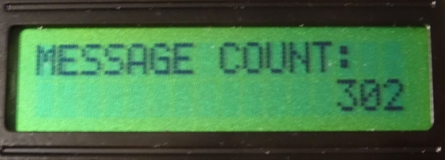
You can calculate the percentage based on the total nr of msg's by getting the total MESSAGE COUNT displayed at Counters page and combine that with the values from FAIL and NACK on the Statistics page.
-
@benbidouille said in nRF24Doctor:
I thought the percentage shown corresponds to Nbr_of_fail / Total_Counter, but it is not and i assume percentage is rather calculated over last X
It is indeed calculated over the last 100 msg's. In that way you have some "real-time" feedback on your connection quality (i.e. suppose you would have had 10.000 good msg's and it would start to fail - it will take +/-100 failed msg's to drop a single 1%).
You can calculate the percentage based on the total nr of msg's by getting the total MESSAGE COUNT displayed at Counters page and combine that with the values from FAIL and NACK on the Statistics page.
@Technovation
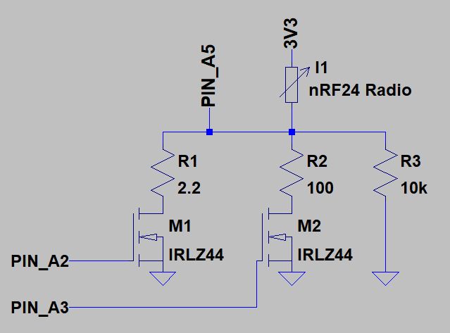
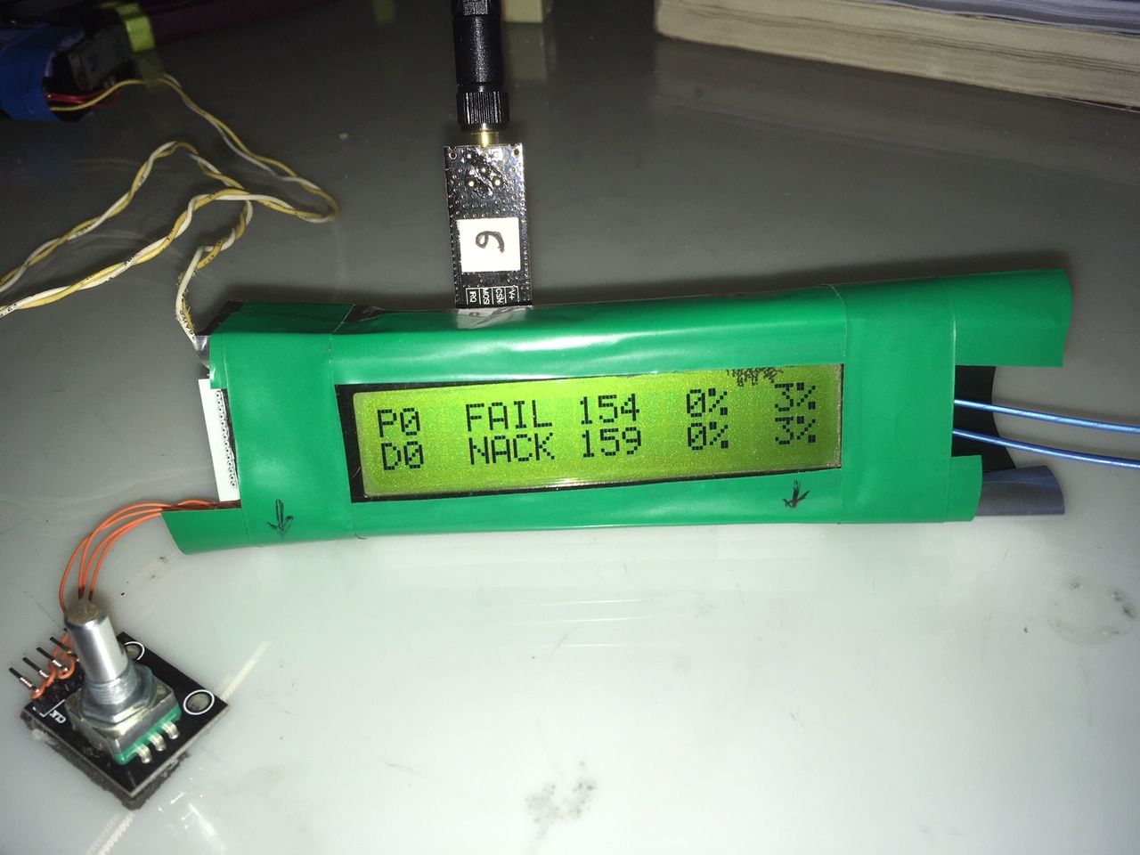
Many thanks, I took opportunity of the only oversized 20x2 LCD device I had, to add the Nbr_of_fail / Total_Counter statistics display, very useful for cumulative % on long run in addition to original last 100 msg.I also wanted to share with you importance of having a proper shielding (underneath green tape is aluminium film) where only Radio OEM module is exposed.
Under PA+LNA in the worst case conditions (max power), shielding significantly increases TX RX reliability (ideally OEM module body should also be shielded)
Cheers
-
@Technovation
Many thanks, I took opportunity of the only oversized 20x2 LCD device I had, to add the Nbr_of_fail / Total_Counter statistics display, very useful for cumulative % on long run in addition to original last 100 msg.I also wanted to share with you importance of having a proper shielding (underneath green tape is aluminium film) where only Radio OEM module is exposed.
Under PA+LNA in the worst case conditions (max power), shielding significantly increases TX RX reliability (ideally OEM module body should also be shielded)
Cheers
Hello,
This is me again
I intended to modify my existing W5100 GW to incorporate Doctor features, W5100 based on an Arduino NANO but I'm facing an architecture issue.Mysensor recommends W5100 GW to use a Soft SPI for the NRF24 Radio as seems W5100 and NRF24 both on same SPI bus fails to operate.
GW Doctor requires IRQ which Soft SPI doesn't support, so sketch fails to compile with below error.
#error RF24 IRQ usage cannot be used with Soft SPI
Has somebody worked-around that situation and succeded to have a W5100 Doctor GW ?
Thanks in advance
-
Hello,
This is me again
I intended to modify my existing W5100 GW to incorporate Doctor features, W5100 based on an Arduino NANO but I'm facing an architecture issue.Mysensor recommends W5100 GW to use a Soft SPI for the NRF24 Radio as seems W5100 and NRF24 both on same SPI bus fails to operate.
GW Doctor requires IRQ which Soft SPI doesn't support, so sketch fails to compile with below error.
#error RF24 IRQ usage cannot be used with Soft SPI
Has somebody worked-around that situation and succeded to have a W5100 Doctor GW ?
Thanks in advance
@benbidouille you can run W5100 with hardware spi but there are many revisions of the W5100 arduino shield available. Some of them eg require to have a defined state of the SD card select line before mySensors starts. Not a big problem, but you need to understand your hardware.
That's why soft spi is suggested. -
@benbidouille you can run W5100 with hardware spi but there are many revisions of the W5100 arduino shield available. Some of them eg require to have a defined state of the SD card select line before mySensors starts. Not a big problem, but you need to understand your hardware.
That's why soft spi is suggested.@Yveaux
Thanks a lot for your feedback.I used very basic W5100 HW as on below link link text.
Why MySensor forum do mention "The W5100 ethernet module has problems sharing SPI with radio" recommending to use soft SPI with such unit without SD card ?
I must admit, I implemented sketch and wiring as recommended by MySensor forum with no brainer.
Lots of post like here link text seems also to confirm issues in the way W5100 handles SPI bus, a reel night mare, I haven't found any succesfull experience in forum yet.
Should you have further information or maybe working sketch to share, I would very much appreciate.
I have no logic analyzer so would prefer to avoid entering in long debug session but if you confirm W5100 and NRF on same SPI bus should work, i'll make a trial and rewire mine.
Regards -
@Yveaux
Thanks a lot for your feedback.I used very basic W5100 HW as on below link link text.
Why MySensor forum do mention "The W5100 ethernet module has problems sharing SPI with radio" recommending to use soft SPI with such unit without SD card ?
I must admit, I implemented sketch and wiring as recommended by MySensor forum with no brainer.
Lots of post like here link text seems also to confirm issues in the way W5100 handles SPI bus, a reel night mare, I haven't found any succesfull experience in forum yet.
Should you have further information or maybe working sketch to share, I would very much appreciate.
I have no logic analyzer so would prefer to avoid entering in long debug session but if you confirm W5100 and NRF on same SPI bus should work, i'll make a trial and rewire mine.
Regards@benbidouille I've run multiple gateways using W5100 on hw spi with atmega328 and never had any issues apart from that SD card select line.
I'm not sure why the docs mention there would be a sharing issue.http://yveaux.blogspot.nl
-
@benbidouille I've run multiple gateways using W5100 on hw spi with atmega328 and never had any issues apart from that SD card select line.
I'm not sure why the docs mention there would be a sharing issue.@Yveaux
Thanks so much for confirmation,
Seems a large community of people faced the issue here back in 2014 link text , and the recomendation comes from this past experience.My undertanding is nobody re-challenged the recomendation and possibly are we the only one interested in getting IRQ with NRFDoctor.
So is a good news you confirm it works.
Can I assume you use same W5100 HW shield as mine and that you have for HW connections:- W5100 (CS/MOSI/MISO/CLK) wired respectively on HW SPI (10,11,12,13)
- NRF24 also on HW SPI for (MOSI/MISO/CLK) only and differentiated CS/CE/IRQ on for instance respectively 6/5/2
Regards and thanks for these precious informations that will help me saving time.
Regards -
@benbidouille I've run multiple gateways using W5100 on hw spi with atmega328 and never had any issues apart from that SD card select line.
I'm not sure why the docs mention there would be a sharing issue.@Yveaux said in nRF24Doctor:
I've run multiple gateways using W5100 on hw spi with atmega328 and never had any issues apart from that SD card select line.
Very interesting. I just (few weeks ago) built an Ethernet gateway recently and at the time followed the recommendation for soft SPI. Then more recently I read about hardware SPI being required for
MY_RX_MESSAGE_BUFFER_FEATUREwhich of course would be a valuable feature on a gateway.Did you ever investigate further? Even if not, I will probably do so on my own, sooner or later, as I have a few of the various W5500 cheap modules here...
-
Hya,
correct me if i'm wrong.
To make use of this, two units must be built. One for node and other for gateway.
Is this undestanding correct? If not, how to use nRF24DoctorGateway and nRF24DoctorNode?
Thx in advance.
-
I need some help.
I just built an NRF24Doctor following the instruction in the post and on Github.-
When no NRF24 module is connected, the device starts properly, displays the menu on the LCD, and when I try to select a menu item, it (correctly) displays "Radio init error. Replace radio".
-
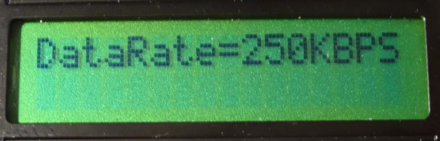
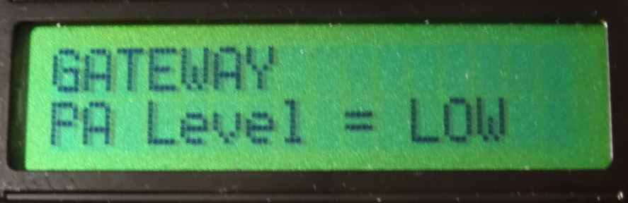
When an NRF24 mode is connected (I tried several), the LCD is blank, the serial monitor shows "Channel:90 PaLevel:HIGH PaLevelGw:LOW DataRate:250KBPS Dest:0 Payload:2 Rate:10" in an endless loop.
-
when I run the older "nRf24L01+ connection quality meter" software, it starts ok and the LCD shows FAIL 0% and MISS 0% as expected.
Any ideas for what might cause this problem? Almost looks like it resets in a loop, maybe because the watchdog triggers? or stack corruption?
-
-
Hello all,
First things first - this is a great device, kudos to everybody involved!
I built a buggy nrf24Doctor - it wasn't measuring the current consumption at all ("xxx Err" message). Trying to fix it led me to refactor the - splitting it into smaller "components" and adapting the project structure to VSCode/platform-io (ArduinoIDE is not my cup of tea).
If someone is interested, the code can be found at github.
Regards,
L. -
Sorry to necro this old post :(
I have just uploaded @yveaux's version of nRF24 doctor to a Nano.@Yveaux said in nRF24Doctor:
https://github.com/TechNovation01/nRF24Doctor/blob/master/pcb/nRFDoctor_1.1_sch.pdf
I got all the right libraries installed into IDE (especially LCDMenuLib2.h version 1.2.7, i also tried several other versions close to 1.2.7 just to be sure).
But when compiling i get the following errors :/tmp/ccMpih6l.ltrans0.ltrans.o: In function `global constructors keyed to 65535_0_nRF24QualityMeter03.ino.cpp.o.3416': <artificial>:(.text.startup+0x19a): undefined reference to `lcdml_menu_display()' <artificial>:(.text.startup+0x19c): undefined reference to `lcdml_menu_display()' <artificial>:(.text.startup+0x1a6): undefined reference to `lcdml_menu_clear()' <artificial>:(.text.startup+0x1a8): undefined reference to `lcdml_menu_clear()' collect2: error: ld returned 1 exit status exit status 1 Erreur de compilation pour la carte Arduino NanoThat is a bit above my knowledge. Could someone please point me into the right direction? Could it be just a case of "wrong naming" of variables ?
-
Sorry to necro this old post :(
I have just uploaded @yveaux's version of nRF24 doctor to a Nano.@Yveaux said in nRF24Doctor:
https://github.com/TechNovation01/nRF24Doctor/blob/master/pcb/nRFDoctor_1.1_sch.pdf
I got all the right libraries installed into IDE (especially LCDMenuLib2.h version 1.2.7, i also tried several other versions close to 1.2.7 just to be sure).
But when compiling i get the following errors :/tmp/ccMpih6l.ltrans0.ltrans.o: In function `global constructors keyed to 65535_0_nRF24QualityMeter03.ino.cpp.o.3416': <artificial>:(.text.startup+0x19a): undefined reference to `lcdml_menu_display()' <artificial>:(.text.startup+0x19c): undefined reference to `lcdml_menu_display()' <artificial>:(.text.startup+0x1a6): undefined reference to `lcdml_menu_clear()' <artificial>:(.text.startup+0x1a8): undefined reference to `lcdml_menu_clear()' collect2: error: ld returned 1 exit status exit status 1 Erreur de compilation pour la carte Arduino NanoThat is a bit above my knowledge. Could someone please point me into the right direction? Could it be just a case of "wrong naming" of variables ?
I might be able to answer that myself !
Looks like i have forgotten to "combine" a .ino file (CharLcdMenu.ino) with the main one (nRF24DoctorNode.ino), which seems to be a bit like a sub-program.
edit: that's it. Just had to create a second TAB with that sub-program, compile and success.
Please forgive my lack of vocabulary and knowldge, i am a "copy-paste" engineer :D
-
It's great when a project can be brought to life after 8 years!
-
It's great when a project can be brought to life after 8 years!
@OldSurferDude as long as we’re using nRFs this project is still relevant :D
Great little tool to check for efficiency of modules
I can even « aim » a pcb antenna to get the best result !
Hello! It looks like you're interested in this conversation, but you don't have an account yet.
Getting fed up of having to scroll through the same posts each visit? When you register for an account, you'll always come back to exactly where you were before, and choose to be notified of new replies (either via email, or push notification). You'll also be able to save bookmarks and upvote posts to show your appreciation to other community members.
With your input, this post could be even better 💗
Register Login