💬 MySensors InCan double light switch
-
I haven't started on my project yet, so I am glad to read some more information here.
@stormy: could you please add a bit of documentation and/or links to (english) documentation about how to put the bootloader on the atmel? Personally I haven't done this before; my Arduino's already had the right bootloader. I would like to know what the recommended uploader would be (maybe with a link or picture?) and what the recommended procedure would be to upload this.
Thanks for opening my eyes about this @magpern :-)
@rolandow To burn a bootloader you need an ISP. I have used a cheap Chinese clone like this one
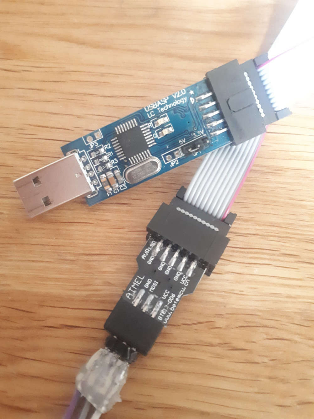 .
.
I have used Arduino IDE to burn the bootloader, but you can use other things too, like AVRDUDE.
A word of warning when using the Arduino IDE is that it also sets the fuses. So, you have to select the correct board type when you set the bootloader with this program (or change the fuses in the boards.txt file).
I bricked two atmega328 before I realized this.
In this post you can read a little about the flashing, or atleast it has links to other pages.You can probably skip the bootloader all together and just upload the sketch with the ISP instead, but you wont be able to upload with serial in that case.
After the bootloader, you can upload with a FTDI. I also use a cheap clone like this one
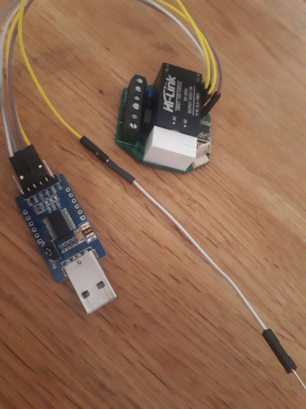
I also use the Arduino IDE to upload the sketch, just select the correct serial/com port in the IDE.The "InCan double light switch" does not auto-reset when upload starts, so you have to reset it manually. The white/yellow cable is connected to RESET on the ISP connector, and after I choose Upload in Arduino IDE and the build output in the IDE window is finished I touch the white/yellow cable to GND on the FTDI device, and the leds on the FTDI starts blinking.
Device is now programmed.
Good to think off is that the crypto chip is connected to A4, instead of A3. So if you use this and run the personalizer sketch, you have to set
#define MY_SIGNING_ATSHA204_PIN A4in the sketch
Also, the original code for this device is not compatible with the MySensors development branch, but can easily be adopted, just comparing to the default MySensors RelayActuator sketch
-
No, a have no problems with sketch.
It looks like some problems with radio communication.Diodes are only for protection transistor from reverse voltage spikes. Diodes never should be even warm. Something is wrong. You can test this without diodes.
47uF for radio is C6, you do not need to add next one.
@rolandow
There are a lot of manuals on the internet.
For example:
https://www.arduino.cc/en/Tutorial/ArduinoToBreadboard
https://www.circuito.io/blog/atmega328p-bootloader/
https://www.instructables.com/id/Burning-the-Bootloader-on-ATMega328-using-Arduino-/
https://www.instructables.com/id/How-to-Burn-the-Arduino-BootLoader-on-to-a-AtMega3/ -
No, a have no problems with sketch.
It looks like some problems with radio communication.Diodes are only for protection transistor from reverse voltage spikes. Diodes never should be even warm. Something is wrong. You can test this without diodes.
47uF for radio is C6, you do not need to add next one.
@rolandow
There are a lot of manuals on the internet.
For example:
https://www.arduino.cc/en/Tutorial/ArduinoToBreadboard
https://www.circuito.io/blog/atmega328p-bootloader/
https://www.instructables.com/id/Burning-the-Bootloader-on-ATMega328-using-Arduino-/
https://www.instructables.com/id/How-to-Burn-the-Arduino-BootLoader-on-to-a-AtMega3/@stormy said in 💬 MySensors InCan double light switch:
No, a have no problems with sketch.
It looks like some problems with radio communication.It was. I used the default channel and apparently it was too noicy. Changed to another channel and it worked fine!
Diodes are only for protection transistor from reverse voltage spikes. Diodes never should be even warm. Something is wrong. You can test this without diodes.
Somehow, when powered by 5V from the FTDI, the device got hot. The Hi-link maybe did not like to get power from the FTDI? The diodes got super hot, and so did the Hi-link. I removed the diodes and could continue. Today, I tried 230V. It didn't work, the thermo fuse was busted, probably from the overheating earlier.
I shorted the fuse (temporarily) and everything worked fine. Hi-link was still alive and supplied 5 Volts
And this brings me to my question...What kind of range do you get with this device? And how accurate is it?
I tried 50 centimeters from the gateway and got a fairly decent hit rate on the on/off from domoticz.
I moved the device to about 3-4 meters, and maybe got 50% hit rate. It was almost line of sight.
If I toggle the on/off from Domotics, with 3 seconds apart, I got like 10% hit rate, maybe every 10th click toggled the relay.
Placing it inside a wall sounds like a "no go" if almost line of sight doesn't work 100%.What is your experience?
-
@magpern:
It should never be hot. The thermal fuse should not be hot. Something is wrong with your module.About range:
With module mounted inside wall (in in-wall can, below wall switch) it works fine about 10 meters from gateway.
Currently I have 5 modules working well for 6 months.
The only one problem I have is with poor quality Hongfa mini relays - some of these sometimes get sticky contacts and I need to remove wall switch and knock into relay. I changed relay to NPA-AS5 and problem gone.I do not know how to advice you.
I suspect that there is some problem with your module - first try check why it is hot?
Or you live in very noise environment. -
Hello !
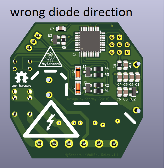
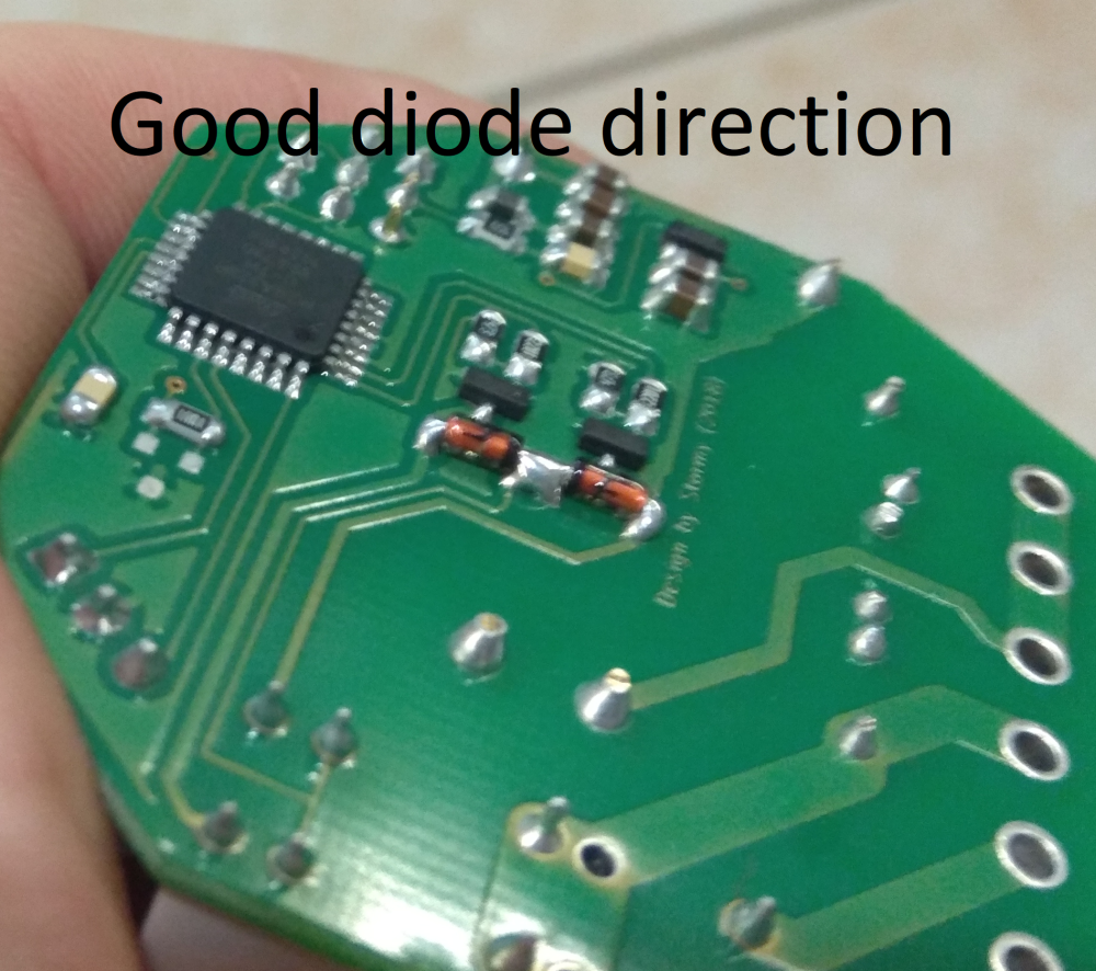
I know that some time has passed but the problems with the heating diodes may be due to the wrong location in the drawings - they are there the opposite than they should be !!! (they should be directed to the inside with minuses as shown in the schematic and on the drawings they are outside) - I had the same thing until I checked
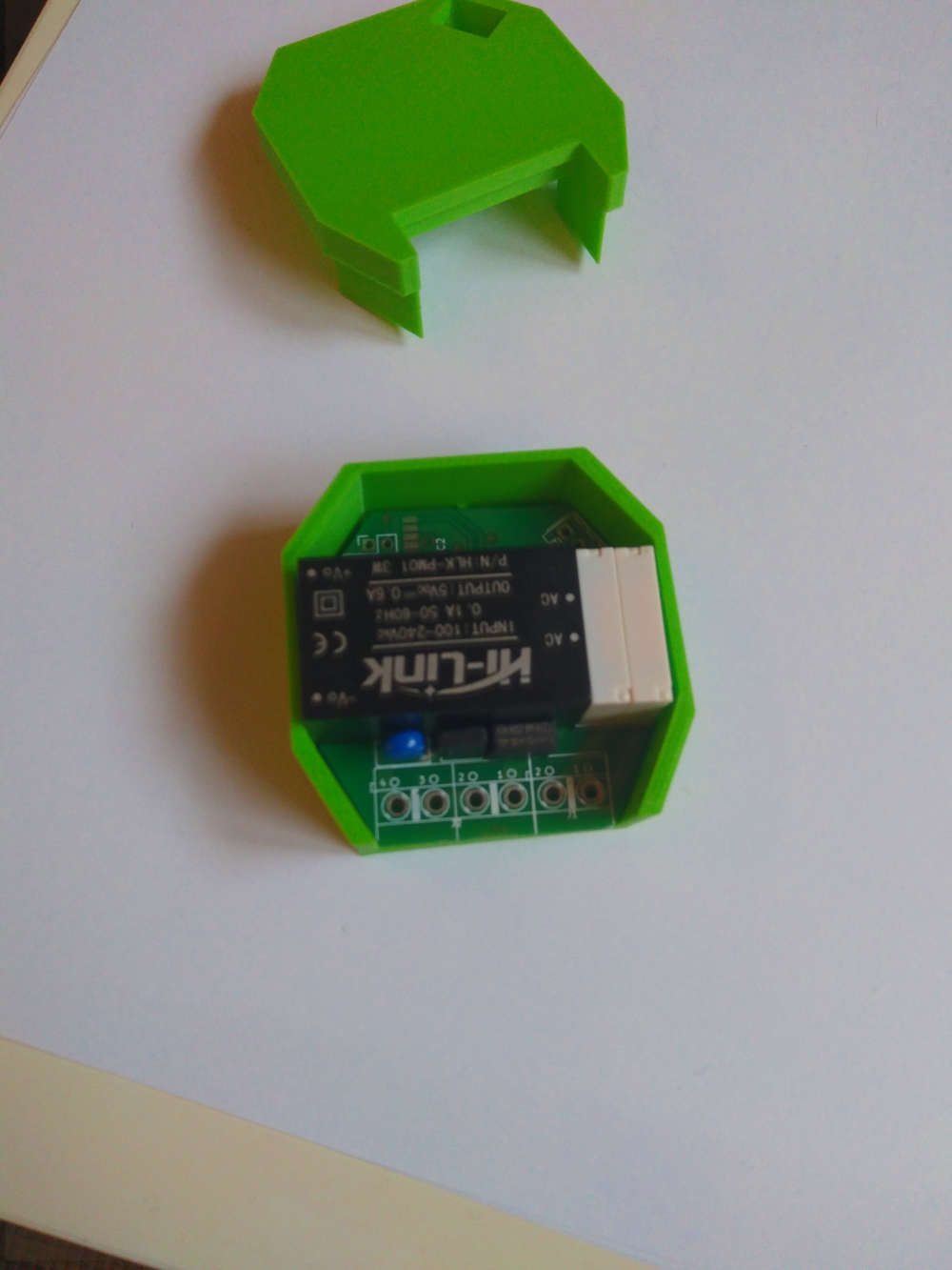
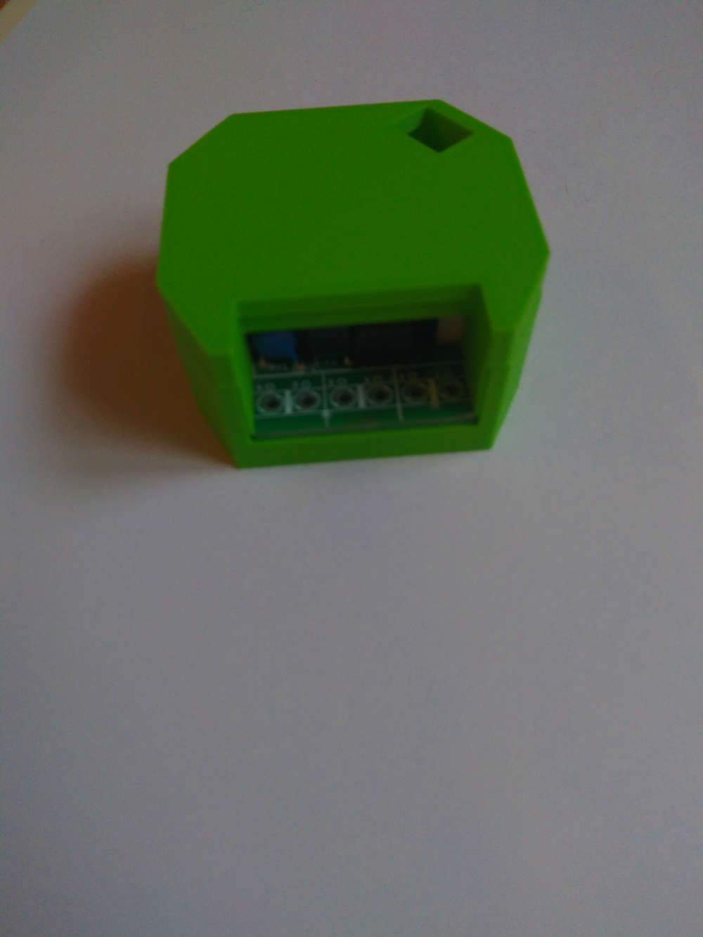
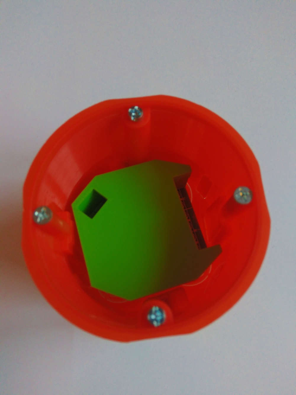
I also designed the housing for 3D printing - if Stormy is interested I can send it for sharing
-
Hello !
I know that some time has passed but the problems with the heating diodes may be due to the wrong location in the drawings - they are there the opposite than they should be !!! (they should be directed to the inside with minuses as shown in the schematic and on the drawings they are outside) - I had the same thing until I checked
I also designed the housing for 3D printing - if Stormy is interested I can send it for sharing
@insectteam I did not understand what you mean about the diods. Could you please clarify or show with pictures?
I have not used the device since it does not feel saft to put in an enclosure if the diods burns hot.
And also, please share your stl files for the enclosure, here or on thingiverse -
-
This post is deleted!
-
I know this is quite an old project and, furthermore, my question is maybe silly but... I expect I could use this switch to pull up/close the window blinds but can I also connect a simple reed contact to some pins as a sensor, whether the window is closed or opened? I only need the information, whether the contact is on or off, sent to MySensors gateway...
-
The author has done some good work ensuring good design practices; trace separation, fuses, etc. but I don't see any extra I/O brought out on this particularl switch. You would have to carefully solder to the chip itself, and modify the code a bit.
You could use magnetic switches. Put a magnet on the blinds and the switch in window sill.
The author notes that this is not an Arduino, but uses the same chip that the Arduino uses. The author doesn't explain how the chip is programmed. This method could have been used.
It may be just as easy to use an RF Nano with a little power supply. This suggestion is not nearly as robust as the author's. For example, these power supplies have gotten bad reviews mainly because the mains power traces are too close together. I justify using them because in all likelihood a failure will pop the power supply and probably the Nano, too, noting that these are cheaper than the fuses you would put in to protect them. I am fully aware of the risks involved in doing this, and you should be, too (eg. burning down your house).
-OSD
Hello! It looks like you're interested in this conversation, but you don't have an account yet.
Getting fed up of having to scroll through the same posts each visit? When you register for an account, you'll always come back to exactly where you were before, and choose to be notified of new replies (either via email, or push notification). You'll also be able to save bookmarks and upvote posts to show your appreciation to other community members.
With your input, this post could be even better 💗
Register Login