Power conservation with battery powered sensors
-
I am working on my battery powered sensors and would like to verify a couple of things about cutting traces to reduce power consumption.
http://www.mysensors.org/build/battery#general-tips-for-battery-operation
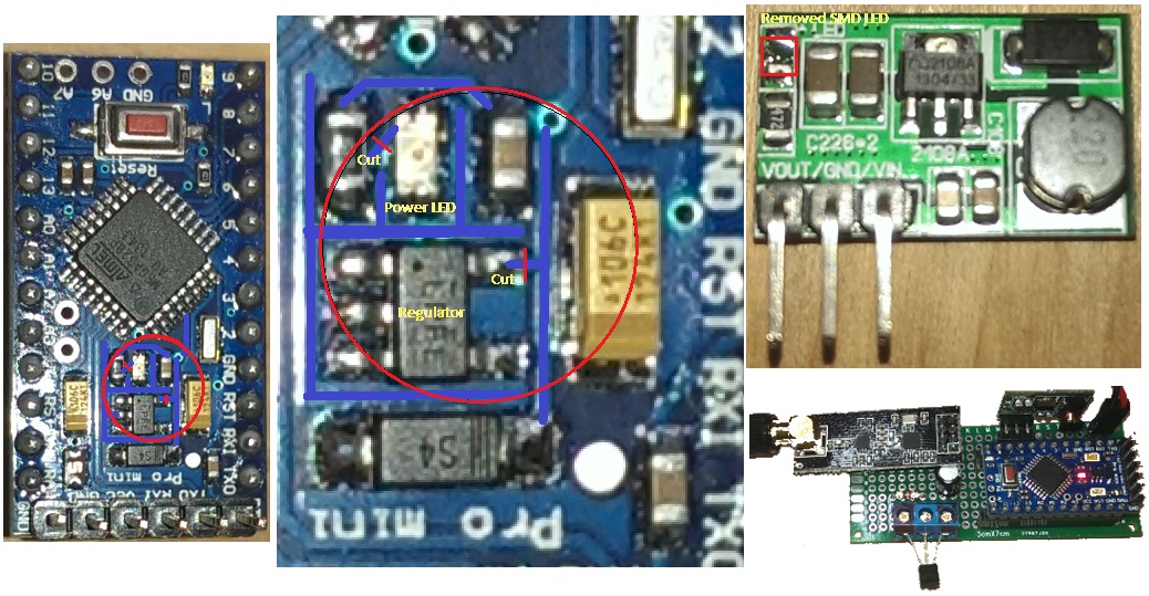
This link shows where to cut traces to remove the power LED and on board regulator. My Arduino is a little different. It is a Deek-Robot 3.3v Pro Mini and the layout is a little different. I am confident that I have the right leads, but just want to double check with you guys, so I don’t trash a pro mini. See the image (sorry for the poor quality, best my phone could do). I enhanced the image by drawing solid blue where the traces are on the board with RED slashes were I believe the cuts should be.
Also using the DC/DC Input 0.8-3V, Output 3.3V. Step Up Power Converter I removed the LED from the board and I still get the 3.3v out, so I am good there.
Just for reference
I tested with the regulator and LED in place as well as the LED on the Step Up. I used the base mySensor temp sketch, with a sleep cycle of 32000ms, since currently the 1.4beta is limited to 32367 (integer) for its sleep duration. I got about 4 days with these parameters. I have since adjusted the library sleep function to long and will be testing again, when I confirm the trace cuts for my pro model.Thanks
Those were the correct traces to cut for the Deek-Robot 3.3v Pro Mini.
No power light
No regulator (note: you will only be able to upload your sketches when only using the the FTDI adapter with the pro mini, since any radio and senors will receive no power - attach your battery power for these to receive power and be able to debug the sketch).Set the sketch up to sleep for 60 seconds and received temperature readings just fine. Bumped it up to 3600 seconds once per hour (as this is the target interval I am after) to see how long the battery will last.
-
Thanks for documentation this, I have different hardware but I am very interested in the battery life.
-
It has been about 2 weeks since I put two temperature sensors in an attic placement, with 2AA Alkaline and they are both reporting 100% battery life – so I am hopeful they will last a while.
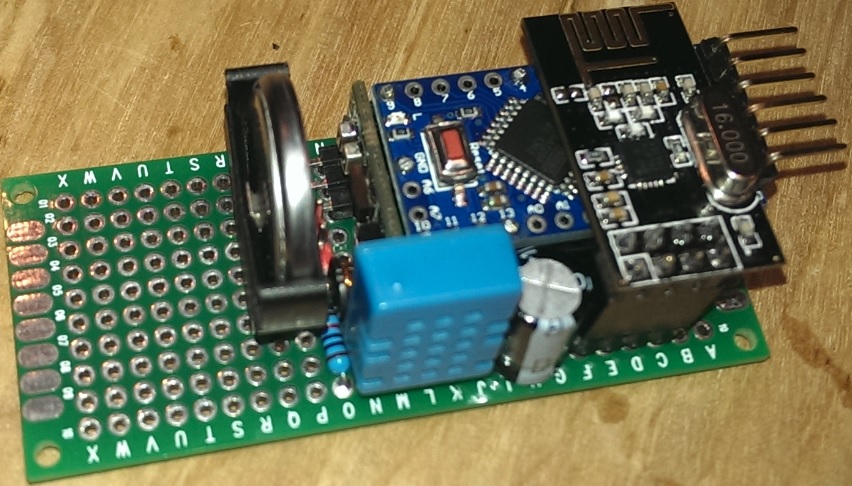
I just put together a DHT11 Sensor with a CR2023 v3.3 Lithium battery. Anybody using this type of battery or have any experience with how long they might last, with a wake up once per hour? Regulator trace was cut and the led removed from the 3.3v pro mini.
Thanks
-
Hi,
I've the same pro mini from deek robot.
I already smashed two of them. I cut the line from the voltage regulator, after this modification they do not work as before.
The last one is not respondig to the ftdi adapter but the led is on.
Has anybody a hint for me what's going wrong?
-
Hi,
I've the same pro mini from deek robot.
I already smashed two of them. I cut the line from the voltage regulator, after this modification they do not work as before.
The last one is not respondig to the ftdi adapter but the led is on.
Has anybody a hint for me what's going wrong?
-
Good thing about cuts is that you easy can reverse the mod by scratch off some paint and short it back again with a solder blob. If still broken you've probably bricked it by ESD or something.
-
I am working on my battery powered sensors and would like to verify a couple of things about cutting traces to reduce power consumption.
http://www.mysensors.org/build/battery#general-tips-for-battery-operation
This link shows where to cut traces to remove the power LED and on board regulator. My Arduino is a little different. It is a Deek-Robot 3.3v Pro Mini and the layout is a little different. I am confident that I have the right leads, but just want to double check with you guys, so I don’t trash a pro mini. See the image (sorry for the poor quality, best my phone could do). I enhanced the image by drawing solid blue where the traces are on the board with RED slashes were I believe the cuts should be.
Also using the DC/DC Input 0.8-3V, Output 3.3V. Step Up Power Converter I removed the LED from the board and I still get the 3.3v out, so I am good there.
Just for reference
I tested with the regulator and LED in place as well as the LED on the Step Up. I used the base mySensor temp sketch, with a sleep cycle of 32000ms, since currently the 1.4beta is limited to 32367 (integer) for its sleep duration. I got about 4 days with these parameters. I have since adjusted the library sleep function to long and will be testing again, when I confirm the trace cuts for my pro model.Thanks
@lininger Anyway, have anyone realize the consumption every deek-robot pro mini (before cutting the power regulator and led) are not the same?
My first board takes 3.2mA while the other takes 2.4mA. All using the same battery, nrf24l01+ radio also sketch. And until now, I don't know where's the differences...
-
@Sidey I had sames experience few days ago.. What i do is that I check the bootloader condition. I dont know if my case same with you, but I do that and its working well now.
Hi, the bootload is not really my problem. Connection via Programmer is also not possible.
I've checkd the connections again and again.
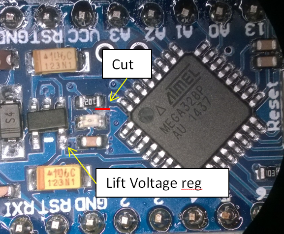
Not i think, i have another revision from the deek robot. I really have two diffent revisions. Layout seems same but they are not from the same production.But I've figured out that the lines in the picture at the first post are a little bit differnt as with my pro mini.
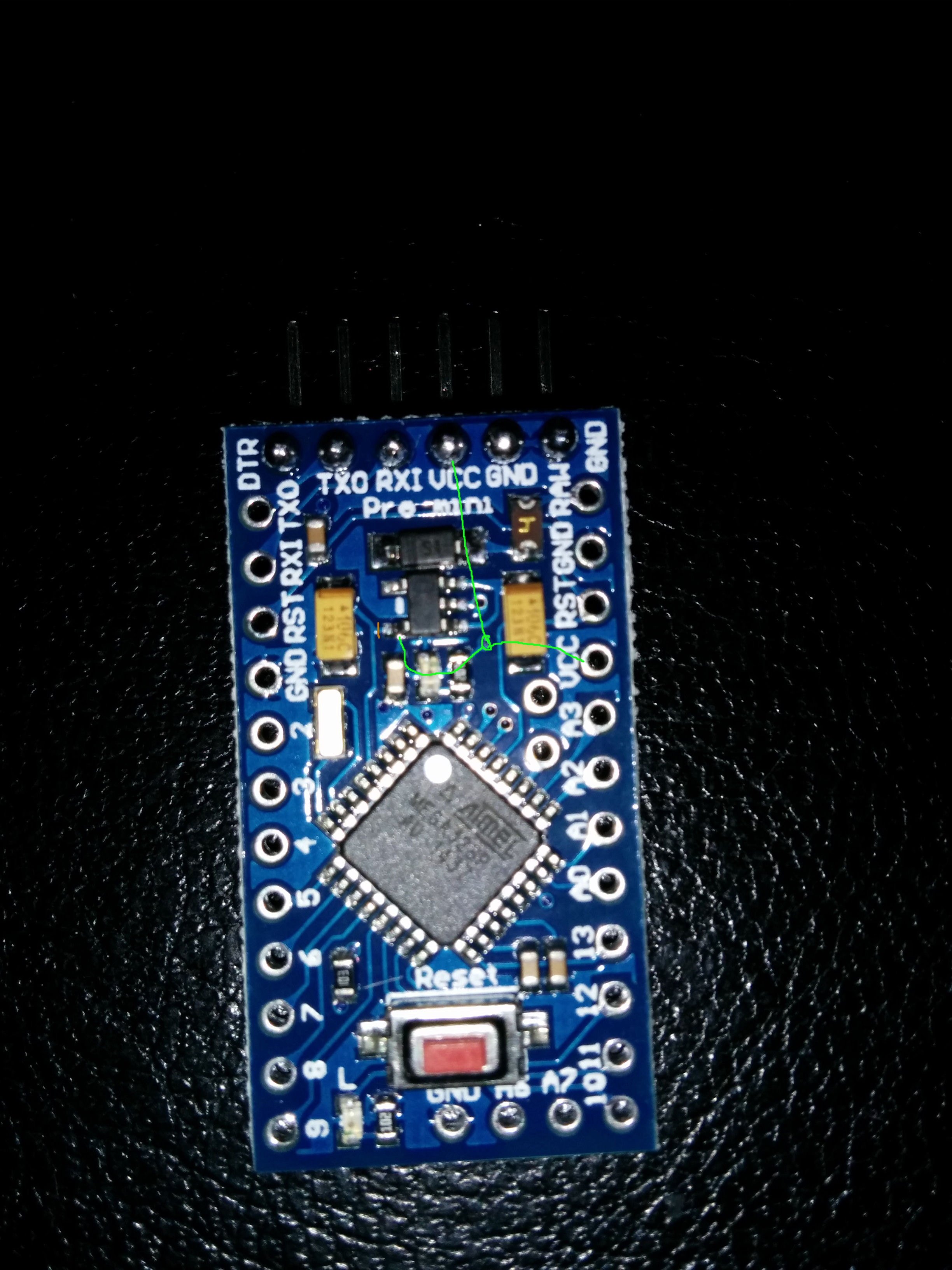
I've made a cut directly at the regulator. And that it's the problem. The connection to vcc is exactly at this position. I've checked this with a jumper wire. Bringing back the connection let the uc run.
I've attatched a photo. Red is the cut, green is the vcc connection.
Sidey -
I have the same problems - anyone solved it?
Deek robot dies when you try to remove the voltage regulator.
Also its different consumption on each robot.Br
-
@Sweebee Hi - thank you for this!
I can also comfirm, desoldering the voltage regulator and not using the FTDI VCC does work.
The deek-robot i tried to cut the trace shown in Battery page killed it so i had to resolder it.@hek maybe we should mention this on the battery page?
I think a battery WIKI would be awsome... :) -
There are just too many clones out there...
But I've been thinking of setting up a wiki for some time. The problem is to find out a good integration with the forum (same user base and and perhaps use the forum commenting on wiki articles). An open blogging platform for the community members to show off their projects/research might be a better choice.
-
I always desolder it completley, easiest way and you dont have to cut.
I also desolders the voltage regulator in my battery operations.
Works great on a pro mini (deek robot) -
I always desolder it completley, easiest way and you dont have to cut.
I also desolders the voltage regulator in my battery operations.
Works great on a pro mini (deek robot)@sundberg84
I also on my last work removed the LG33, it's faster :-)
Well this most likely have been provided as info, but else it's here:
Remember to burn new OPTIBOOT 8MHz into the Arduino Pro Mini
and then I also use avrdude with a usbtinyISP to set the fuse to not check battery voltage monitoring, this is done after I have flashed this with Arduino IDEavrdude -c usbtiny -p m328p -U efuse:w:0x07:m```
Hello! It looks like you're interested in this conversation, but you don't have an account yet.
Getting fed up of having to scroll through the same posts each visit? When you register for an account, you'll always come back to exactly where you were before, and choose to be notified of new replies (either via email, or push notification). You'll also be able to save bookmarks and upvote posts to show your appreciation to other community members.
With your input, this post could be even better 💗
Register Login