Using nrf24l01+ with other devices together on one SPI-Bus.
-
I was looking into using an second device on the spi-bus next to the nrf24.
I've seen that most sketches (if not all) are using the soft-spi library to achive a second spi-device next to the nrf24.Nevertheless i decided to investigate why this isn't possibly with most devices to use one bus.
And i probably found the problem for some devices:
https://github.com/mysensors/Arduino/blob/development/libraries/MySensors/utility/RF24.cpp#L23Deleting this 3 lines out of the RF24.cpp gave me 2 fully operational devices on one SPI-Bus.
Has anyone experience with this?
I tested this with an 16mhz nano @ 250kbps -
That is a great discovery. I was wondering hot to accomplish it, because in theory it's possible. I have found an arduino memory extension which is also SPI. Thank you very much for your investigation.
-
Yes, i've managed to have communication with a second SPI device next to the NRF24L01+ module. I have connected a Mifare RC522 RFID reader using the SPI bus.
The NRF24L01+ is connect as suggested on the MySensors site.- pin 2 IRQ
- pin 9 CE
- pin 10 CSN/CS
- pin 11 MOSI
- pin 12 MISO
- pin 13 SCK
The RC522 module shares pin
- pin 11 MOSI
- pin 12 MISO
- pin 13 SCK
and uses
- pin 7 (iso 9) for CE
- pin 8 (iso 10) for CSN/CS
If your SPI module needs an IRQ also use a different pin for pin 2 (IRQ) as well
The pin CE and CS will make sure that only one SPI slave will communicate over the SPI bus.
What i had to do before gw.begin() is called (i initialize MySensors before the RC522) is setting both the CE (pin 7) and CSN (pin 8 ) to LOW so the RC522 is disconnected from the SPI bus.#define RST_PIN 7 #define SS_PIN 8 void setup() { // First make sure mfrc is releasing the SPI bus pinMode(RST_PIN, OUTPUT); digitalWrite(RST_PIN, LOW); pinMode(SS_PIN, OUTPUT); digitalWrite(SS_PIN, LOW); // Init mysensors library gw.begin(incomingMessage); // Init MFRC RFID sensor SPI.begin(); // Init SPI bus mfrc522.PCD_Init(); // Init MFRC522 // do some more init stuff } -
-
Yes, i've managed to have communication with a second SPI device next to the NRF24L01+ module. I have connected a Mifare RC522 RFID reader using the SPI bus.
The NRF24L01+ is connect as suggested on the MySensors site.- pin 2 IRQ
- pin 9 CE
- pin 10 CSN/CS
- pin 11 MOSI
- pin 12 MISO
- pin 13 SCK
The RC522 module shares pin
- pin 11 MOSI
- pin 12 MISO
- pin 13 SCK
and uses
- pin 7 (iso 9) for CE
- pin 8 (iso 10) for CSN/CS
If your SPI module needs an IRQ also use a different pin for pin 2 (IRQ) as well
The pin CE and CS will make sure that only one SPI slave will communicate over the SPI bus.
What i had to do before gw.begin() is called (i initialize MySensors before the RC522) is setting both the CE (pin 7) and CSN (pin 8 ) to LOW so the RC522 is disconnected from the SPI bus.#define RST_PIN 7 #define SS_PIN 8 void setup() { // First make sure mfrc is releasing the SPI bus pinMode(RST_PIN, OUTPUT); digitalWrite(RST_PIN, LOW); pinMode(SS_PIN, OUTPUT); digitalWrite(SS_PIN, LOW); // Init mysensors library gw.begin(incomingMessage); // Init MFRC RFID sensor SPI.begin(); // Init SPI bus mfrc522.PCD_Init(); // Init MFRC522 // do some more init stuff }@BartE Can you tell me where connect SDA, RST from RC522 module? i cant find information about alternative names on that pins... also can you share code for nrf24+rc522?
-
@Michał-Owsianka Yes
@BartE said:
pin 7 (iso 9) for CE
pin 8 (iso 10) for CSN/CSPin 7 CE == RST
Pin 8 CSN/CS == SDAThe init part of the code can be found in my earlier post
The rest of the library is taken from the mfrc522 example code. https://github.com/miguelbalboa/rfidTo share my Sketch i do need to cleanup and test again the Sketch because it does (much) more. Like reading temperature and air pressure.
@BartE said:
@Michał-Owsianka Yes
@BartE said:
pin 7 (iso 9) for CE
pin 8 (iso 10) for CSN/CSPin 7 CE == RST
Pin 8 CSN/CS == SDAThe init part of the code can be found in my earlier post
The rest of the library is taken from the mfrc522 example code. https://github.com/miguelbalboa/rfidTo share my Sketch i do need to cleanup and test again the Sketch because it does (much) more. Like reading temperature and air pressure.
Thanks a lot!
-
@Michał-Owsianka : i cleaned the code and uploaded the full sketch here: http://forum.mysensors.org/topic/2439/rfid-garage-door-opener
-
I was trying to make NRF24 and ADXL345 work on the same SPI bus. Each device worked ok individually, but not together, when used by the same program. After some investigation, using a logic analyzer (listening to the SPI pins and to the CS pins of both devices), I managed to solve the problem. What I found was:
-
NRF24 (TMRH20 library) sets SPI settings before each SPI transaction it makes. It uses SPI_MODE0, MSBFIRST, SPI speed up to 10 MHz (not 100% sure about the max speed).
-
ADXL (SparkFun library) does not change existing SPI settings before its transactions. It seems to do it only once when creating an instance of the device
ADXL345 adxl = ADXL345(ADXL_ChipSelect_PIN);Therefore, the first NRF24 transaction modifies SPI settings, disabling the ADXL345. ADXL345 uses SPI_MODE3. MSBFIRST. SPI speed up to 5 MHz, according to the specs.
So, here is how I made them work together: In the code, before each ADXL transaction I insert:
SPI.beginTransaction(SPISettings(4000000, MSBFIRST, SPI_MODE3));andSPI.endTransaction();at the end of each transaction. The detailed description can be found here. I didn’t have to use SPI settings before NRF24 SPI transactions because, as already mentioned above, the RF24 library does it.Here is an exemplary code, which seems to work fine.
#include <SPI.h>
#include <nRF24L01.h>
#include <RF24.h>
#include <SparkFun_ADXL345.h>
ADXL345 adxl = ADXL345(10);

RF24 radio(8, 9);
const byte address[6] = "00001";

void setup() {
SPI.begin();
  radio.begin();
  radio.openWritingPipe(address);
  radio.setPALevel(RF24_PA_MIN);
  radio.stopListening();
SPI.beginTransaction(SPISettings(4000000, MSBFIRST, SPI_MODE3)); //SPI seetings for ADXL
  adxl.powerOn();
  adxl.setRangeSetting(2);
  adxl.setRate(3200);
  adxl.setSpiBit(0);
SPI.endTransaction(); //SPI seetings for ADXL
}

void loop() {
  int x,y,z;
SPI.beginTransaction(SPISettings(4000000, MSBFIRST, SPI_MODE3));//SPI seetings for ADXL
   adxl.readAccel(&x, &y, &z);
SPI.endTransaction();//SPI seetings for ADXL

int val = x;
  radio.write(&val, sizeof(val));
  		delay(500);
}
Here is the logic analyzer view of the working SPI communication of both devices. One can see SPI modes changing before each transaction.
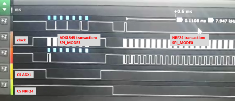
And I didn’t delete the 3 lines, mentioned by Oitzu in the beginning of this post. If I did, NRF24 would not be able to set SPI the way it needs (namely MODE0) before each transaction. I guess, the devices of Oitzu were using the same mode, therefore deleting the SPI settings didn’t harm in that particular case. Please correct me if I’m wrong.
I hope it helps. -
Hello! It looks like you're interested in this conversation, but you don't have an account yet.
Getting fed up of having to scroll through the same posts each visit? When you register for an account, you'll always come back to exactly where you were before, and choose to be notified of new replies (either via email, or push notification). You'll also be able to save bookmarks and upvote posts to show your appreciation to other community members.
With your input, this post could be even better 💗
Register Login