How To - Doorbell Automation Hack
-
Going to install one of these very soon.
How hard would it be to modify the sketch for a two door bell system?
@drock1985 Sorry for the delayed reply! It shouldn't be too hard. You will just have to create another button input and relay output in the sketch. I haven't looked at the code but you should be able to duplicate what's in there just changing the names and pins where appropriate.
-
@drock1985 Sorry for the delayed reply! It shouldn't be too hard. You will just have to create another button input and relay output in the sketch. I haven't looked at the code but you should be able to duplicate what's in there just changing the names and pins where appropriate.
-
Hey @petewill
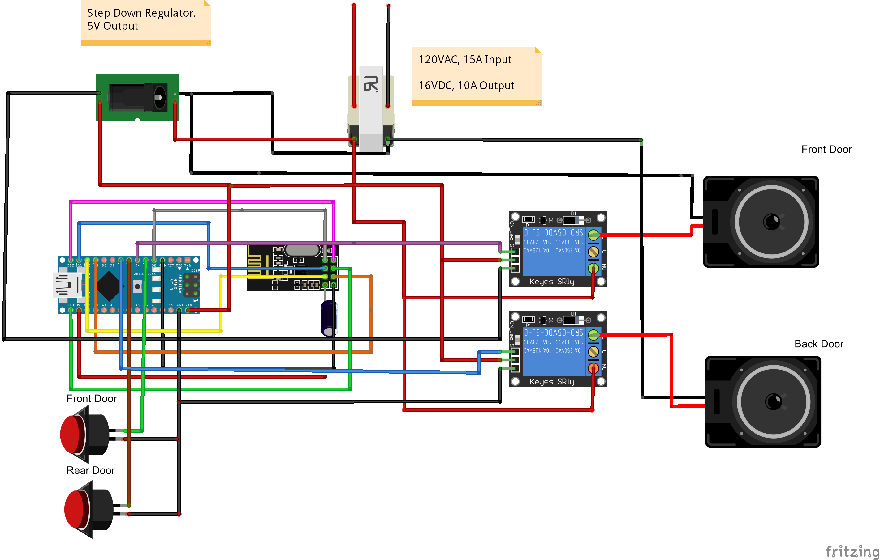
Started working on the project this weekend. Didn't get the parts in this week due to the holiday. Did what I could though, and I have a schematic/drawing made up for the system. This is my first drawing in fritzing, so it's a little crude. I couldn't figure out how to add a 'T' section/junction in the wire, but it all lines up for reference anyways.
I'll start working on the Arduino code next.
-
Hi @hek
I'm not too sure I understand what you are referring to. If you are referring to the buttons themselves outside being wireless, I thought about it but wasn't too sure how long a battery would last and didn't want to be changing batteries. The way I plan to do this now, I can use the existing wiring for the doorbells that are already there, and splice into the power for the door bell to power the MySensors node.
Plus, both chimes are in the same spot, one relay sets off one set of the three contacts (Wtih a common ground I believe) and the other will chime the second.
-
Ahh. nice. Thought you might have to run some new wires around the house.
-
@drock1985 Nice! Does your doorbell use DC so you can steal power from it? I wish mine did. That would have made things easier for me. Mine uses 16VAC... :(
-
Hey @petewill
They vary. Some of the more expensive ones I've noticed use DC (ex play custom songs/tones), while the cheaper ones use AC.
I built the project around the idea the wife would want something more elaborate than a simple ding sound, but I was wrong lol. So I picked up one that she looked last night, and I believe it uses AC, so I will be making a slight change to my design.
I'll end up putting in one of these I figure, just haven't quite figured out what size smoothing capacitor I will need.
Also, I'm not 100% sure yet (at work, hard to do research) but I may be able to get away with a simple 5v regulator once the power is converted to DC, in lieu of a variable buck converter.
My Projects
2 Door Chime Sensor
Washing Machine Monitor -
@BulldogLowell Haha, I just took the easy way out and ran a 5V line :)
I built the project around the idea the wife would want something more elaborate than a simple ding sound, but I was wrong lol.
Yeah, that's happened to me as well on other projects :)
-
Hey @petewill
They vary. Some of the more expensive ones I've noticed use DC (ex play custom songs/tones), while the cheaper ones use AC.
I built the project around the idea the wife would want something more elaborate than a simple ding sound, but I was wrong lol. So I picked up one that she looked last night, and I believe it uses AC, so I will be making a slight change to my design.
I'll end up putting in one of these I figure, just haven't quite figured out what size smoothing capacitor I will need.
Also, I'm not 100% sure yet (at work, hard to do research) but I may be able to get away with a simple 5v regulator once the power is converted to DC, in lieu of a variable buck converter.
@drock1985 said:
I'll end up putting in one of these I figure, just haven't quite figured out what size smoothing capacitor I will need.
Add a cap .1uf input side of the 5V regulator and a 47-220uf on the regulated 5V . High freq and a low freq ripple.
That should do the trick same thing I was planning on doing. I bought the Ring Doorbell but still want to be notified of the actual ring into HA.
-
Hi @petewill
I finally got the parts in to do the project. I've been working on the code, but I seem to be running into an issue. I have the four devices show up in Domoticz, but I'm not getting any feedback from the sensor. Would you mind looking at the code for me please? This is the first program I have ever worked on, and not much of a programmer mentality yet.
/* * The MySensors Arduino library handles the wireless radio link and protocol * between your home built sensors/actuators and HA controller of choice. * The sensors forms a self healing radio network with optional repeaters. Each * repeater and gateway builds a routing tables in EEPROM which keeps track of the * network topology allowing messages to be routed to nodes. * * Created by Henrik Ekblad <henrik.ekblad@mysensors.org> * Copyright (C) 2013-2015 Sensnology AB * Full contributor list: https://github.com/mysensors/Arduino/graphs/contributors * * Documentation: http://www.mysensors.org * Support Forum: http://forum.mysensors.org * * This program is free software; you can redistribute it and/or * modify it under the terms of the GNU General Public License * version 2 as published by the Free Software Foundation. * ******************************* * * REVISION HISTORY * * 2 Door Chime * Version 1.0 - ResentedPoet * DESCRIPTION * Original idea/concept by PeteWill. Modified code to add second actuator (relay) * door chimes with 2 doors. This will allow your home automation system to differentiate * between front and back door. As well, this allows current 2 door chimes to still have * their individual chimes. Pins 3 and 4 are used for door bell 1 and relay/chime 1 * respectively, and digital pins 5 and 6 for door bell 2 and relay/chime 2. */ #include <MySensor.h> #include <SPI.h> #include <Bounce2.h> #define NODE_ID AUTO // or set a manual ID in place of AUTO #define DOORBELL1_PIN 3 // Arduino Digital I/O pin number for the doorbell button #define RELAY1_PIN 4 // Arduino Digital I/O pin number for the relay #define DOORBELL1_CHILD_ID 0 //ID of the front doorbell #define SWITCH1_CHILD_ID 1 // Id of the switch that will control front doorbell sound #define RELAY1_ON 1 #define RELAY1_OFF 0 #define DOORBELL2_PIN 5 // Arduino Digital I/O pin number for the doorbell button #define RELAY2_PIN 6 // Arduino Digital I/O pin number for the relay #define DOORBELL2_CHILD_ID 2 //ID of the back doorbell #define SWITCH2_CHILD_ID 3 // Id of the switch that will control back doorbell sound #define RELAY2_ON 1 #define RELAY2_OFF 0 Bounce debouncer = Bounce(); MySensor gw; MyMessage switchMsg1(SWITCH1_CHILD_ID, V_LIGHT); MyMessage switchMsg2(SWITCH2_CHILD_ID, V_LIGHT); MyMessage doorbellMsg1(DOORBELL1_CHILD_ID, V_TRIPPED); MyMessage doorbellMsg2(DOORBELL2_CHILD_ID, V_TRIPPED); unsigned int doorbellDelay = 1000; // interval at which to keep the doorbell button sensor triggered (milliseconds). This is used to stop people (kids) from pressing it too often unsigned int ringTime = 700; //How long the doorbell relay is on (in milliseconds) unsigned long doorbell1Millis; //Used to keep track of the last front doorbell button press unsigned long doorbell1Timer; //Used to keep track of front doorbell ring time unsigned long doorbell2Millis; //Used to keep track of the last back doorbell button press unsigned long doorbell2Timer; //Used to keep track of back doorbell ring time byte doorbell1PreviousVal; //Used to keep track of front doorbell button pressed state byte doorbell2PreviousVal; //Used to keep track of back doorbell button pressed state boolean ringDoorbell1; //Used to initiate the ring front doorbell if statement boolean doorbell1Sound; //Used to keep track if the front doorbell should sound or be silent. Value recieved from doorbell on/off switch boolean doorbell1Off = true; //Used to keep track of front doorbell ring state boolean ringDoorbell2; //Used to initiate the ring front doorbell if statement boolean doorbell2Sound; //Used to keep track if the front doorbell should sound or be silent. Value recieved from doorbell on/off switch boolean doorbell2Off = true; //Used to keep track of front doorbell ring state void setup() { gw.begin(incomingMessage, NODE_ID); // Send the sketch version information to the gateway and Controller gw.sendSketchInfo("2 Doorbell Monitor", "1.0"); // Setup the button and activate internal pull-up pinMode(DOORBELL1_PIN, INPUT_PULLUP); pinMode(DOORBELL2_PIN, INPUT_PULLUP); // After setting up the button, setup debouncer debouncer.attach(DOORBELL1_PIN); debouncer.attach(DOORBELL2_PIN); debouncer.interval(5); // Register all sensors to gw (they will be created as child devices) gw.present(SWITCH1_CHILD_ID, S_LIGHT); gw.present(DOORBELL1_CHILD_ID, S_MOTION); gw.present(SWITCH2_CHILD_ID, S_LIGHT); gw.present(DOORBELL2_CHILD_ID, S_MOTION); // Make sure relays are off when starting up digitalWrite(RELAY1_PIN, RELAY1_OFF); digitalWrite(RELAY2_PIN, RELAY2_OFF); // Then set relay pins in output mode pinMode(RELAY1_PIN, OUTPUT); pinMode(RELAY2_PIN, OUTPUT); // Set doorbellSound to last known state (using eeprom storage) doorbell1Sound = gw.loadState(SWITCH1_CHILD_ID); doorbell2Sound = gw.loadState(SWITCH2_CHILD_ID); } void loop() { gw.process(); unsigned long current1Millis = millis(); //Check to see if front doorbell button was pushed. if (current1Millis - doorbell1Millis > doorbellDelay) //used to stop doorbell from being pressed too frequently { debouncer.update(); // Read front doorbell button value byte doorbell1Detect = !debouncer.read();//read, then reverse the value so it will send correct trigger state to controller if (doorbell1Detect != doorbell1PreviousVal) { //Serial.print("doorbell1Detect Value: "); //Serial.println(doorbell1Detect); if (doorbell1Detect == 1) { ringDoorbell1 = true; doorbell1Timer = current1Millis; } doorbell1Millis = current1Millis; doorbell1PreviousVal = doorbell1Detect; } } if (ringDoorbell1) { if (doorbell1Sound) { if (doorbell1Off) { digitalWrite(RELAY1_PIN, RELAY1_ON); //Serial.println("Front Doorbell sounded."); doorbell1Off = false; } else { if (current1Millis - doorbell1Timer > ringTime) { ringDoorbell1 = false; digitalWrite(RELAY1_PIN, RELAY1_OFF); //Serial.println("Front Doorbell off."); doorbell1Off = true; } } } } //Check to see if back doorbell button was pushed. unsigned long current2Millis = millis(); if (current2Millis - doorbell2Millis > doorbellDelay) //used to stop doorbell from being pressed too frequently { debouncer.update(); // Read back doorbell button value byte doorbell2Detect = !debouncer.read();//read, then reverse the value so it will send correct trigger state to controller if (doorbell2Detect != doorbell2PreviousVal) { //Serial.print("doorbell2Detect Value: "); //Serial.println(doorbell2Detect); if (doorbell2Detect == 1) { ringDoorbell2 = true; doorbell2Timer = current2Millis; } doorbell2Millis = current2Millis; doorbell2PreviousVal = doorbell2Detect; } } if (ringDoorbell2) { if (doorbell2Sound) { if (doorbell2Off) { digitalWrite(RELAY2_PIN, RELAY2_ON); //Serial.println("Back Doorbell sounded."); doorbell2Off = false; } else { if (current2Millis - doorbell2Timer > ringTime) { ringDoorbell2 = false; digitalWrite(RELAY2_PIN, RELAY2_OFF); //Serial.println("Back Doorbell off."); doorbell2Off = true; } } } } } void incomingMessage(const MyMessage & message) { // We only expect one type of message from controller. But we better check anyway. if (message.isAck()) { Serial.println("This is an ack from gateway"); } if (message.type == V_LIGHT) { // Change relay state doorbell1Sound = message.getBool(); // Store state in eeprom gw.saveState(SWITCH1_CHILD_ID, doorbell1Sound); // Write some debug info Serial.print("Incoming change for sensor:"); Serial.print(message.sensor); Serial.print(", New status: "); Serial.println(message.getBool()); } }``` -
@BulldogLowell Haha, I just took the easy way out and ran a 5V line :)
I built the project around the idea the wife would want something more elaborate than a simple ding sound, but I was wrong lol.
Yeah, that's happened to me as well on other projects :)
Haha, I just took the easy way out and ran a 5V line
that may be the easy way, but not as fun :(
-
Hi @petewill
I finally got the parts in to do the project. I've been working on the code, but I seem to be running into an issue. I have the four devices show up in Domoticz, but I'm not getting any feedback from the sensor. Would you mind looking at the code for me please? This is the first program I have ever worked on, and not much of a programmer mentality yet.
/* * The MySensors Arduino library handles the wireless radio link and protocol * between your home built sensors/actuators and HA controller of choice. * The sensors forms a self healing radio network with optional repeaters. Each * repeater and gateway builds a routing tables in EEPROM which keeps track of the * network topology allowing messages to be routed to nodes. * * Created by Henrik Ekblad <henrik.ekblad@mysensors.org> * Copyright (C) 2013-2015 Sensnology AB * Full contributor list: https://github.com/mysensors/Arduino/graphs/contributors * * Documentation: http://www.mysensors.org * Support Forum: http://forum.mysensors.org * * This program is free software; you can redistribute it and/or * modify it under the terms of the GNU General Public License * version 2 as published by the Free Software Foundation. * ******************************* * * REVISION HISTORY * * 2 Door Chime * Version 1.0 - ResentedPoet * DESCRIPTION * Original idea/concept by PeteWill. Modified code to add second actuator (relay) * door chimes with 2 doors. This will allow your home automation system to differentiate * between front and back door. As well, this allows current 2 door chimes to still have * their individual chimes. Pins 3 and 4 are used for door bell 1 and relay/chime 1 * respectively, and digital pins 5 and 6 for door bell 2 and relay/chime 2. */ #include <MySensor.h> #include <SPI.h> #include <Bounce2.h> #define NODE_ID AUTO // or set a manual ID in place of AUTO #define DOORBELL1_PIN 3 // Arduino Digital I/O pin number for the doorbell button #define RELAY1_PIN 4 // Arduino Digital I/O pin number for the relay #define DOORBELL1_CHILD_ID 0 //ID of the front doorbell #define SWITCH1_CHILD_ID 1 // Id of the switch that will control front doorbell sound #define RELAY1_ON 1 #define RELAY1_OFF 0 #define DOORBELL2_PIN 5 // Arduino Digital I/O pin number for the doorbell button #define RELAY2_PIN 6 // Arduino Digital I/O pin number for the relay #define DOORBELL2_CHILD_ID 2 //ID of the back doorbell #define SWITCH2_CHILD_ID 3 // Id of the switch that will control back doorbell sound #define RELAY2_ON 1 #define RELAY2_OFF 0 Bounce debouncer = Bounce(); MySensor gw; MyMessage switchMsg1(SWITCH1_CHILD_ID, V_LIGHT); MyMessage switchMsg2(SWITCH2_CHILD_ID, V_LIGHT); MyMessage doorbellMsg1(DOORBELL1_CHILD_ID, V_TRIPPED); MyMessage doorbellMsg2(DOORBELL2_CHILD_ID, V_TRIPPED); unsigned int doorbellDelay = 1000; // interval at which to keep the doorbell button sensor triggered (milliseconds). This is used to stop people (kids) from pressing it too often unsigned int ringTime = 700; //How long the doorbell relay is on (in milliseconds) unsigned long doorbell1Millis; //Used to keep track of the last front doorbell button press unsigned long doorbell1Timer; //Used to keep track of front doorbell ring time unsigned long doorbell2Millis; //Used to keep track of the last back doorbell button press unsigned long doorbell2Timer; //Used to keep track of back doorbell ring time byte doorbell1PreviousVal; //Used to keep track of front doorbell button pressed state byte doorbell2PreviousVal; //Used to keep track of back doorbell button pressed state boolean ringDoorbell1; //Used to initiate the ring front doorbell if statement boolean doorbell1Sound; //Used to keep track if the front doorbell should sound or be silent. Value recieved from doorbell on/off switch boolean doorbell1Off = true; //Used to keep track of front doorbell ring state boolean ringDoorbell2; //Used to initiate the ring front doorbell if statement boolean doorbell2Sound; //Used to keep track if the front doorbell should sound or be silent. Value recieved from doorbell on/off switch boolean doorbell2Off = true; //Used to keep track of front doorbell ring state void setup() { gw.begin(incomingMessage, NODE_ID); // Send the sketch version information to the gateway and Controller gw.sendSketchInfo("2 Doorbell Monitor", "1.0"); // Setup the button and activate internal pull-up pinMode(DOORBELL1_PIN, INPUT_PULLUP); pinMode(DOORBELL2_PIN, INPUT_PULLUP); // After setting up the button, setup debouncer debouncer.attach(DOORBELL1_PIN); debouncer.attach(DOORBELL2_PIN); debouncer.interval(5); // Register all sensors to gw (they will be created as child devices) gw.present(SWITCH1_CHILD_ID, S_LIGHT); gw.present(DOORBELL1_CHILD_ID, S_MOTION); gw.present(SWITCH2_CHILD_ID, S_LIGHT); gw.present(DOORBELL2_CHILD_ID, S_MOTION); // Make sure relays are off when starting up digitalWrite(RELAY1_PIN, RELAY1_OFF); digitalWrite(RELAY2_PIN, RELAY2_OFF); // Then set relay pins in output mode pinMode(RELAY1_PIN, OUTPUT); pinMode(RELAY2_PIN, OUTPUT); // Set doorbellSound to last known state (using eeprom storage) doorbell1Sound = gw.loadState(SWITCH1_CHILD_ID); doorbell2Sound = gw.loadState(SWITCH2_CHILD_ID); } void loop() { gw.process(); unsigned long current1Millis = millis(); //Check to see if front doorbell button was pushed. if (current1Millis - doorbell1Millis > doorbellDelay) //used to stop doorbell from being pressed too frequently { debouncer.update(); // Read front doorbell button value byte doorbell1Detect = !debouncer.read();//read, then reverse the value so it will send correct trigger state to controller if (doorbell1Detect != doorbell1PreviousVal) { //Serial.print("doorbell1Detect Value: "); //Serial.println(doorbell1Detect); if (doorbell1Detect == 1) { ringDoorbell1 = true; doorbell1Timer = current1Millis; } doorbell1Millis = current1Millis; doorbell1PreviousVal = doorbell1Detect; } } if (ringDoorbell1) { if (doorbell1Sound) { if (doorbell1Off) { digitalWrite(RELAY1_PIN, RELAY1_ON); //Serial.println("Front Doorbell sounded."); doorbell1Off = false; } else { if (current1Millis - doorbell1Timer > ringTime) { ringDoorbell1 = false; digitalWrite(RELAY1_PIN, RELAY1_OFF); //Serial.println("Front Doorbell off."); doorbell1Off = true; } } } } //Check to see if back doorbell button was pushed. unsigned long current2Millis = millis(); if (current2Millis - doorbell2Millis > doorbellDelay) //used to stop doorbell from being pressed too frequently { debouncer.update(); // Read back doorbell button value byte doorbell2Detect = !debouncer.read();//read, then reverse the value so it will send correct trigger state to controller if (doorbell2Detect != doorbell2PreviousVal) { //Serial.print("doorbell2Detect Value: "); //Serial.println(doorbell2Detect); if (doorbell2Detect == 1) { ringDoorbell2 = true; doorbell2Timer = current2Millis; } doorbell2Millis = current2Millis; doorbell2PreviousVal = doorbell2Detect; } } if (ringDoorbell2) { if (doorbell2Sound) { if (doorbell2Off) { digitalWrite(RELAY2_PIN, RELAY2_ON); //Serial.println("Back Doorbell sounded."); doorbell2Off = false; } else { if (current2Millis - doorbell2Timer > ringTime) { ringDoorbell2 = false; digitalWrite(RELAY2_PIN, RELAY2_OFF); //Serial.println("Back Doorbell off."); doorbell2Off = true; } } } } } void incomingMessage(const MyMessage & message) { // We only expect one type of message from controller. But we better check anyway. if (message.isAck()) { Serial.println("This is an ack from gateway"); } if (message.type == V_LIGHT) { // Change relay state doorbell1Sound = message.getBool(); // Store state in eeprom gw.saveState(SWITCH1_CHILD_ID, doorbell1Sound); // Write some debug info Serial.print("Incoming change for sensor:"); Serial.print(message.sensor); Serial.print(", New status: "); Serial.println(message.getBool()); } }```I think your code is a little hard to get through, but you need two instances of the Bounce library if you want to manage two buttons:
  debouncer.attach(DOORBELL1_PIN);
  debouncer.attach(DOORBELL2_PIN);
do this instead:
//...
Bounce debouncePin1 = Bounce();
Bounce debouncePin2 = Bounce();
//...
void setup()
{
  //...
  debouncePin1.attach(DOORBELL1_PIN);
  debouncePin1.interval(5);
  debouncePin2.attach(DOORBELL2_PIN);
  debouncePin2.interval(5);
  //...
}
and update the state with:
debouncerPin1.update();get it?
alternatively you could use an array:
Bounce debouncer[2] = Bounce();it would make your code a lot easier, but you have to understand arrays and Classes or you will be a little lost.
-
Haha, I just took the easy way out and ran a 5V line
that may be the easy way, but not as fun :(
-
I did take a look at my doorbell last night. I have a transformer down in the basement that's outputting 16VAC. Then the doorbell upstairs, with no convenient place to get power from. The wires from both the doorbell button and the transformer come to the doorbell "box" on the wall.
At first I was looking for a way to convert the 16VAC to 5VDC. Then as I was looking at the space in the doorbell to mount the board, I saw two more wires not connected to anything. They ran 4 conductor wire from the transformer to the bell! Sweet! So now I'll put a 5V source (probably phone charger to USB cable with the end cut off) in the basement, connect that to the other unused pair of wires, and have my power where I need it.
Is there any issue with running the 5V DC power and the 16VAC power alongside each other? It's not like either is carrying data, so I don't think there would be...
-
Hi,
Just a quick question. I'm trying the original code for the doorbell, and I have it registering in Domoticz just great,. I have two lights, one to turn off the relay and the other, not sure of (thought it would turn on if doorbell was tripped). Anyways, did I miss something or did domoticz register it as the wrong item?
Thanks,
Hello! It looks like you're interested in this conversation, but you don't have an account yet.
Getting fed up of having to scroll through the same posts each visit? When you register for an account, you'll always come back to exactly where you were before, and choose to be notified of new replies (either via email, or push notification). You'll also be able to save bookmarks and upvote posts to show your appreciation to other community members.
With your input, this post could be even better 💗
Register Login