Backlit Dimmable LED Mirror with Motion Sensor
-
@petewill I add a light sensor to your sketch and this now slow everything down what will the reason for this be? The motion sensor will not always pickup motion. I have another node with light and motion sensor and that is working right.
Here is the code:
/*** * This program is free software; you can redistribute it and/or * modify it under the terms of the GNU General Public License * version 2 as published by the Free Software Foundation. * * DESCRIPTION * This sketch provides a Dimmable LED Light using PWM and based Henrik Ekblad * <henrik.ekblad@gmail.com> Vera Arduino Sensor project. * Developed by Bruce Lacey, inspired by Hek's MySensor's example sketches. * * The circuit uses a MOSFET for Pulse-Wave-Modulation to dim the attached LED or LED strip. * The MOSFET Gate pin is connected to Arduino pin 3 (MIRROR_LED_PIN), the MOSFET Drain pin is connected * to the LED negative terminal and the MOSFET Source pin is connected to ground. * * This sketch is extensible to support more than one MOSFET/PWM dimmer per circuit. * * REVISION HISTORY * Version 1.0 - February 15, 2014 - Bruce Lacey * Version 1.1 - February 4, 2014 - Pete B - added buttons to control on/off and dim level and a motion sensor ***/ #define SN "Mirror LED with PIR and LDR" #define SV "1.2" #define NODE_ID 50 //change to a number to assign a specific ID #include <SPI.h> #include <MySensor.h> #include <Bounce2.h> #include <MySigningNone.h> #include <MyTransportNRF24.h> #include <MyHwATMega328.h> #define MIRROR_LED_CHILD 0 //ID of the LED child #define MOTION_CHILD 1 //ID of the motion sensor child #define CHILD_ID_LIGHT 2 //ID for LDR sensor #define LIGHT_SENSOR_ANALOG_PIN 0 // NRFRF24L01 radio driver (set low transmit power by default) MyTransportNRF24 radio(RF24_CE_PIN, RF24_CS_PIN, RF24_PA_LEVEL_GW); #define MIRROR_LED_PIN 3 // Arduino pin attached to MOSFET Gate pin #define UP_BUTTON_PIN 8 // Arduino Digital I/O pin number for the fade up button #define DOWN_BUTTON_PIN 7 // Arduino Digital I/O pin number for the fade down button #define POWER_BUTTON_PIN 4 // Arduino Digital I/O pin number for the power button #define MOTION_PIN 6 // Arduino pin tied to trigger pin on the motion sensor. #define FADE_DELAY 10 // Delay in ms for each percentage fade up/down (10ms = 1s full-range dim) #define FADE_PERCENTAGE 10 //The percentage the fade level will be changed when a button is pressed MyHwATMega328 hw; // Construct MySensors library MySensor gw(radio, hw); //MySensor gw; //Don't need to define pins unless they are changing from the default static int currentLevel = 0; // Current dim level... uint8_t fadeLevel = 0; //used to store the fade level when using the buttons uint8_t upPreviousValue; uint8_t downPreviousValue; uint8_t powerPreviousValue; Bounce upDebouncer = Bounce(); Bounce downDebouncer = Bounce(); Bounce powerDebouncer = Bounce(); //motion sensor uint8_t lastMotion = 0; unsigned long previousMillis = 0; // last time update //see http://stackoverflow.com/questions/10773425/performing-a-function-after-x-time for more details on this unsigned long motionDelay = 10000; // interval at which to keep motion sensor trippped (milliseconds). Used to prevent too frequent updates to Vera. unsigned long upPreviousMillis = 0; unsigned long downPreviousMillis = 0; unsigned long buttonFadeDelay = 200; int lastLightLevel; boolean metric = true; MyMessage motionMsg(MOTION_CHILD, V_TRIPPED); MyMessage dimmerMsg(MIRROR_LED_CHILD, V_DIMMER); MyMessage msg(CHILD_ID_LIGHT, V_LIGHT_LEVEL); //MyMessage lightMsg(LED_CHILD, V_LIGHT); removed, updating with dimmer values only /*** * Dimmable LED initialization method */ void setup() { Serial.println( SN ); gw.begin( incomingMessage, NODE_ID); // Register the LED Dimmable Light with the gateway gw.present(MIRROR_LED_CHILD, S_DIMMER ); gw.present(MOTION_CHILD, S_MOTION); gw.present(CHILD_ID_LIGHT, S_LIGHT_LEVEL); // Send the sketch version information to the gateway and Controller gw.sendSketchInfo(SN, SV); metric = gw.getConfig().isMetric; // Setup the button pinMode(UP_BUTTON_PIN,INPUT); pinMode(DOWN_BUTTON_PIN,INPUT); pinMode(POWER_BUTTON_PIN,INPUT); // Activate internal pull-up digitalWrite(UP_BUTTON_PIN,HIGH); digitalWrite(DOWN_BUTTON_PIN,HIGH); digitalWrite(POWER_BUTTON_PIN,HIGH); // After setting up the button, setup debouncer upDebouncer.attach(UP_BUTTON_PIN); downDebouncer.attach(DOWN_BUTTON_PIN); powerDebouncer.attach(POWER_BUTTON_PIN); upDebouncer.interval(5); downDebouncer.interval(5); powerDebouncer.interval(5); } /*** * Dimmable LED main processing loop */ void loop() { //process the LED commands from gateway gw.process(); int lightLevel = (1023-analogRead(LIGHT_SENSOR_ANALOG_PIN))/10.23; // Serial.println(lightLevel); if (lightLevel != lastLightLevel) { gw.send(msg.set(lightLevel)); lastLightLevel = lightLevel; } //motion sensor code unsigned long currentMillis = millis(); if(currentMillis - previousMillis > motionDelay){ uint8_t motionDetect = digitalRead(MOTION_PIN); if(motionDetect != lastMotion){ // Serial.print("motionDetect Value: "); // Serial.println(motionDetect); gw.send(motionMsg.set(motionDetect)); // Send tripped value to gw if(motionDetect == 1){ previousMillis = currentMillis; //"Tripped" delay } else{ previousMillis = currentMillis - motionDelay + 1000; //"Not tripped" delay for 1 second to stop rapid "not tripped" and "tripped" updates to Vera } lastMotion = motionDetect; } } /* There are 3 buttons attached to the mirror. One is an on/off button and the other two will fade up/fade down. The sensor will remember the last fade state and fade the lights to that level next time they are turned on. If fade up or fade down button is pressed it should store that value into a variable and when the ON button is pressed it will fade to that previous value. */ upDebouncer.update(); // Get the update value uint8_t upValue = upDebouncer.read(); unsigned long upCurrentMillis = millis(); if(upCurrentMillis - upPreviousMillis > buttonFadeDelay){ if ((upValue == LOW) && (fadeLevel<100)) { //Because of the internal pullup resistors LOW = button is presssed fadeLevel += FADE_PERCENTAGE; fadeLevel = fadeLevel > 100 ? 100 : fadeLevel; fadeToLevel( fadeLevel ); } upPreviousMillis = upCurrentMillis; } downDebouncer.update(); // Get the update value uint8_t downValue = downDebouncer.read(); unsigned long downCurrentMillis = millis(); if(downCurrentMillis - downPreviousMillis > buttonFadeDelay){ if ((downValue == LOW) && (fadeLevel>0)) { fadeLevel -= FADE_PERCENTAGE; fadeLevel = fadeLevel < 0 ? 0 : fadeLevel; //powerState = fadeLevel; //Remember fade level for when power button is pressed fadeToLevel( fadeLevel ); } downPreviousMillis = downCurrentMillis; } powerDebouncer.update(); // Get the update value uint8_t powerValue = powerDebouncer.read(); if(powerValue != powerPreviousValue){ if (powerValue == LOW) { Serial.print("Power Button Pressed. fadeLevel is "); Serial.println(fadeLevel); if (currentLevel > 0) { fadeToLevel( 0 ); } else{ if (fadeLevel == 0) { fadeToLevel(50); fadeLevel = 50; } else{ fadeToLevel(fadeLevel); } } } powerPreviousValue = powerValue; } } void incomingMessage(const MyMessage &message) { if (message.type == V_LIGHT || message.type == V_DIMMER) { // Retrieve the power or dim level from the incoming request message int requestedLevel = atoi( message.data ); // Adjust incoming level if this is a V_LIGHT variable update [0 == off, 1 == on] requestedLevel *= ( message.type == V_LIGHT ? 100 : 1 ); // Clip incoming level to valid range of 0 to 100 requestedLevel = requestedLevel > 100 ? 100 : requestedLevel; requestedLevel = requestedLevel < 0 ? 0 : requestedLevel; // Serial.print( "Changing level to " ); // Serial.print( requestedLevel ); // Serial.print( ", from " ); // Serial.println( currentLevel ); fadeToLevel( requestedLevel ); } } /*** * This method provides a graceful fade up/down effect */ void fadeToLevel( int toLevel ) { // Serial.print("toLevel Value: "); // Serial.println(toLevel); // Serial.print("currentLevel Value: "); // Serial.println(currentLevel); int delta = ( toLevel - currentLevel ) < 0 ? -1 : 1; while ( currentLevel != toLevel ) { currentLevel += delta; analogWrite( MIRROR_LED_PIN, (int)(currentLevel / 100. * 255) ); delay( FADE_DELAY ); } // Inform the gateway of the current DimmableLED's SwitchPower1 and LoadLevelStatus value... //gw.send(lightMsg.set(currentLevel > 0 ? 1 : 0)); //used to send status of light (on/off) to Vera gw.send( dimmerMsg.set(currentLevel) ); }@Francois I usually put a "millis" delay for all of my sensors that don't need instant updates (temperature, humidity, light, etc). I have had some of my sensors updating too frequently and causing communication issues for the rest of my sensors. Maybe that's what's happening to you? Try adding some code so the light sensor only updates once per 10 seconds or what ever interval you feel is good. You can use my motion sensor code as an example for adding a delay with millis.
-
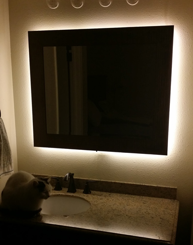
Hi Everyone,I have created backlit mirror based on Bruce Lacey's dimmable LED sketch. I have added a motion sensor and some on/off and fade up/down buttons. There is some logic in the code to save the dim level when the buttons are pressed. I have all my motion turn on/off logic in my Vera controller using PLEG. It could be easily adapted to control the on/off functionality in the Arduino code but I like to have my automation logic in one place (my Vera).
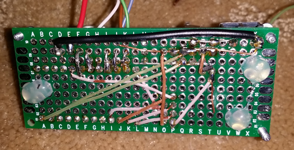
This was a fun project to work on and although it looks pretty ugly from the back my wife loves the way it looks in our master bathroom. I tried to document as best I could but please let me know if you have any questions.
Here is a list of the parts I used
- Items from MySensors Store http://www.mysensors.org/store/
- Female Pin Header Connector Strip
- Prototype Universal Printed Circuit Boards (PCB)
- NRF24L01 Radio
- Arduino Pro Mini
- FTDI USB to TTL Serial Adapter
- Capacitors (10uf and .1uf)
- 3.3v voltage regulator
- 5v voltage regulator
- IRLZ44N Logic Level Transistor MOSFET
- 12v Transformer (power supply)
- 5 Meter LED Strip (I used 3528)
- HC-SR501 PIR Motion Sensor Module
- 22-24 gauge wire or similar (I used Cat5/Cat6 cable)
- 2 Pole 5mm Pitch PCB Mount Screw Terminal Block
Here is a video explaining how to build it yourself.
http://youtu.be/jblaMddRDpc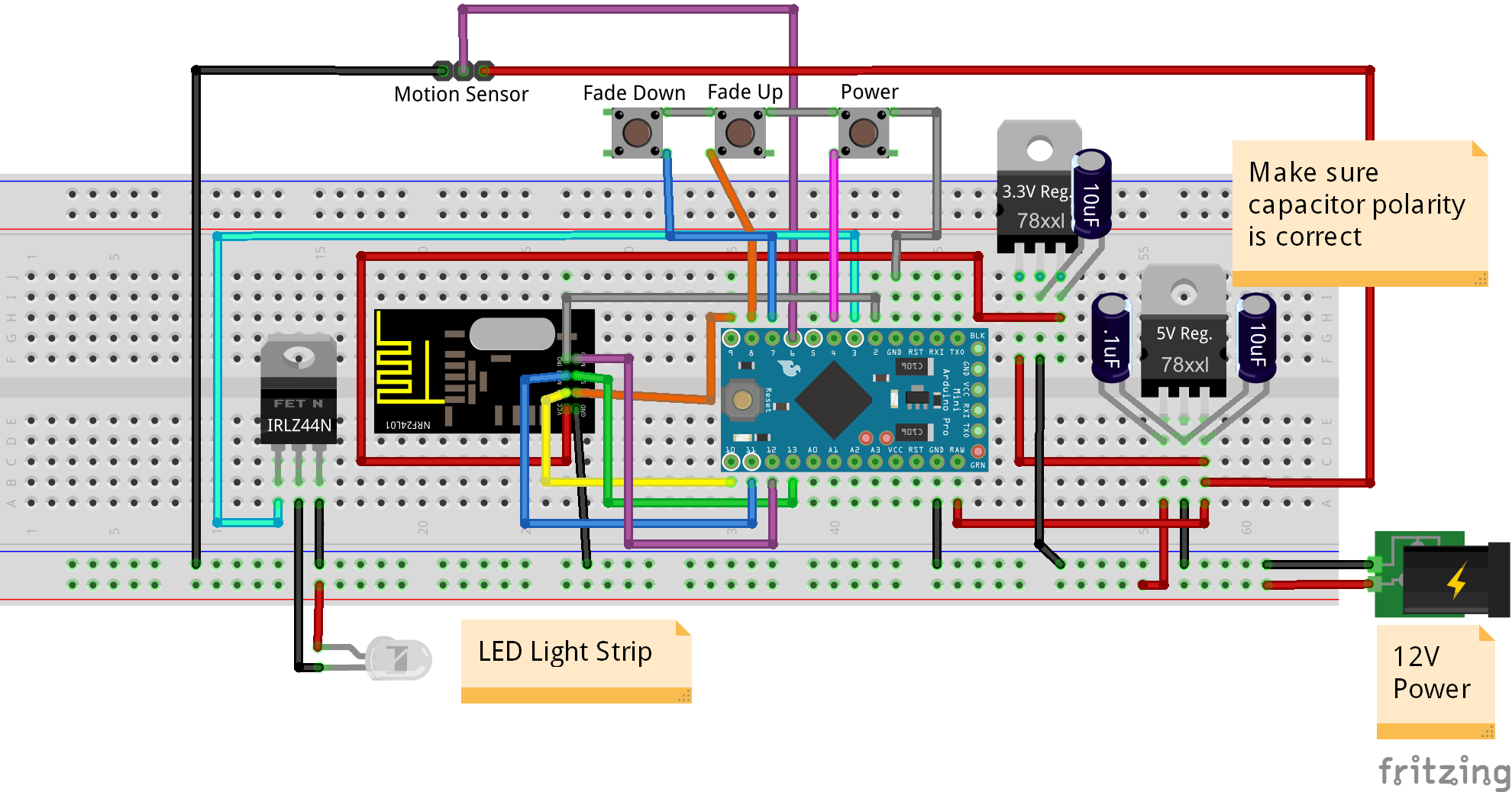
Here is the Fritzing (http://fritzing.org/) wiring diagram file if you want to view in more detail: Mirror LED Wiring Diagram.fzz
https://codebender.cc/sketch:81486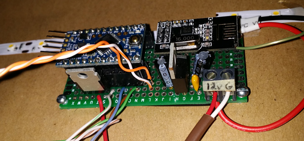
- Items from MySensors Store http://www.mysensors.org/store/
-
@petewill Just wanted to let you know that I've built two of these for my daughters but instead of putting them behind a mirror I put it under their bed. Works really good, thanks for sharing!
-
@petewill Just wanted to let you know that I've built two of these for my daughters but instead of putting them behind a mirror I put it under their bed. Works really good, thanks for sharing!
-
@petewill Just wanted to let you know that I've built two of these for my daughters but instead of putting them behind a mirror I put it under their bed. Works really good, thanks for sharing!
@henno That is too funny I was at a hotel and they had LEDs under the cabinets with motion sensors to light the floor. So when I came home I knew I saw some guy doing something similar to a mirror that I'm gonna steal for under my bed to walk at night without bumping my toes! Thanks Pete!
-
For those of us without a central 12v system do you know what the current draw is?
What is your system setup? Thinking of doing the same.
-
For those of us without a central 12v system do you know what the current draw is?
What is your system setup? Thinking of doing the same.
-
Thanks. I'm hopeing to do a "ehole house" 12v system also. What is your power source. I've been looking at
Thoughts?
-
Thanks. I'm hopeing to do a "ehole house" 12v system also. What is your power source. I've been looking at
Thoughts?
@csa02221862 Depending on what you want to run it may be a little under powered. For the last year and a half I have been using a hacked 300 watt PC power supply. I originally just set it up as a temporary measure but it has been working great. I have even made some stupid wiring mistakes and shorted it out a few times. Each time I just fix the mistake and it powers right back on. I need to make a video of how I set everything up but I have had so little time lately...
-
Thanks for the info. I may get this for use in the "lab" and see what you are doing with the computer power supply when you do the video. I believe many of us would like to have a 12v/5v power distribution system in the house.
Your videos are OUTSTANDING!
-
Looking forward to the "whole house power" video.
I'm building this for two mirrors as well as kitchen under counter and bookcase down lighting.
Your Vera videos have been MOST helpful. You do great "practical" work.
THANKS AGAIN!
-
Looking forward to the "whole house power" video.
I'm building this for two mirrors as well as kitchen under counter and bookcase down lighting.
Your Vera videos have been MOST helpful. You do great "practical" work.
THANKS AGAIN!
@csa02221862 Great! I have these all around my house in various places and I love them. All credit goes to @blacey.
I do need to work on the power video. There are so many things I want to work on I have been focusing on making videos as I work on new sensors. It's so hard to find time these days...
-
I have a question on this project.
I'm replicating it for a wider mirror and I was thinking about having two separate dimming zones ( left and right ). based on the sketch and the design: Do you think One arduino can control both sides or do I need 2 different arduinos (+ electronics) and one won't be enough.
Happy to details more if needed.
thanks in advance!
@Dave-Dan said:
Do you think One arduino can control both sides or do I need 2 different arduinos (+ electronics) and one won't be enough.
Definitely. I have one pro mini controlling 3 different dimmers. You just need to make sure you use PWM pins for the outputs.
-
Do you have the Fitzing and code for the 3 zone? I have several places to use this. Any "max wattage" info, per channel and total?
Thanks,
Richard -
Do you have the Fitzing and code for the 3 zone? I have several places to use this. Any "max wattage" info, per channel and total?
Thanks,
RichardSorry it has been too long since I made this video and I don't remember the reference. If you're talking about my Arduino that dims three separate lights it's basically just the same wiring except you use 3 different PWM pins to the 3 different MOSFETs. The max wattage is determined by the MOSFET you use.
If that's not what you're referring to, let me know.
-
Sorry it has been too long since I made this video and I don't remember the reference. If you're talking about my Arduino that dims three separate lights it's basically just the same wiring except you use 3 different PWM pins to the 3 different MOSFETs. The max wattage is determined by the MOSFET you use.
If that's not what you're referring to, let me know.
@petewill Yes that's what I'm talking about. Just wondering how the code was modified to discretely control the 3 zones.
-
@petewill Yes that's what I'm talking about. Just wondering how the code was modified to discretely control the 3 zones.
@csa02221862 said:
@petewill Yes that's what I'm talking about. Just wondering how the code was modified to discretely control the 3 zones.
you want with or without the buttons?
If with, how would the buttons work?
-
@petewill Yes that's what I'm talking about. Just wondering how the code was modified to discretely control the 3 zones.
@csa02221862 Sorry for the delayed reply. Busy day yesterday. Here is my code that I'm running in my 1.4.1/1.5 environment.
/***
 * This program is free software; you can redistribute it and/or
 * modify it under the terms of the GNU General Public License
 * version 2 as published by the Free Software Foundation.
 *
 * DESCRIPTION
 * This sketch provides a Dimmable LED Light using PWM and based Henrik Ekblad
 * <henrik.ekblad@gmail.com> Vera Arduino Sensor project.
 * Developed by Bruce Lacey, inspired by Hek's MySensor's example sketches.
 *
 * The circuit uses a MOSFET for Pulse-Wave-Modulation to dim the attached LED or LED strip.
 * The MOSFET Gate pin is connected to Arduino pin 3 (LED_PIN), the MOSFET Drain pin is connected
 * to the LED negative terminal and the MOSFET Source pin is connected to ground.
 *
 * This sketch is extensible to support more than one MOSFET/PWM dimmer per circuit.
 *
 * REVISION HISTORY
 * Version 1.0 - February 15, 2014 - Bruce Lacey
 * Version 1.1 - August 13, 2014 - Converted to 1.4 (hek)
 * Version 1.2 - January 22, 2015 - Created a seperate control for the basement LEDs
 * Version 1.3 - March 7, 2015 - Added coat closet LED
 *
 ***/
#define SN "Basement LEDs"
#define SV "1.3"

#include <MySensor.h>
#include <SPI.h>

#define NODE_ID AUTO //Change to a number to manually assign a node ID

#define MASTER_WINDOW_LED_CHILD 0
#define COAT_CLOSET_LED_CHILD 1
#define UPSTAIRS_RAIL_LED_CHILD 30
#define BASEMENT_DESK_LED_CHILD 40

#define MASTER_WINDOW_LED_PIN 3      // Arduino pin attached to MOSFET Gate pin
#define UPSTAIRS_RAIL_LED_PIN 5
#define BASEMENT_DESK_LED_PIN 6
#define COAT_CLOSET_LED_PIN 9

#define FADE_DELAY 10  // Delay in ms for each percentage fade up/down (10ms = 1s full-range dim)

//MySensor gw;
MySensor gw(4, 10);  //Change CE PIN to free up another PWM pin

static int currentLevelUpstairsRail = 0;
static int currentLevelBasementDesk = 0;
static int currentLevelMasterWinLight = 0;
static int currentLevelCoatCloset = 0;


/***
 * Dimmable LED initialization method
 */
void setup()
{
  Serial.println( SN );
  gw.begin( incomingMessage,  NODE_ID);

  // Register the LED Dimmable Light with the gateway
  gw.present(UPSTAIRS_RAIL_LED_CHILD, S_DIMMER );
  gw.present(BASEMENT_DESK_LED_CHILD, S_DIMMER );
  gw.present(MASTER_WINDOW_LED_CHILD, S_DIMMER );
  gw.present(COAT_CLOSET_LED_CHILD, S_DIMMER );

  gw.sendSketchInfo(SN, SV);
}

/***
 *  Dimmable LED main processing loop
 */
void loop()
{
  gw.process();
}


void incomingMessage(const MyMessage &message) {
  if (message.type == V_LIGHT || message.type == V_DIMMER) {

    //  Retrieve the power or dim level from the incoming request message
    int requestedLevel = atoi( message.data );

    // Adjust incoming level if this is a V_LIGHT variable update [0 == off, 1 == on]
    requestedLevel *= ( message.type == V_LIGHT ? 100 : 1 );

    // Clip incoming level to valid range of 0 to 100
    requestedLevel = requestedLevel > 100 ? 100 : requestedLevel;
    requestedLevel = requestedLevel < 0   ? 0   : requestedLevel;

//    Serial.print( "Changing level to " );
//    Serial.println( requestedLevel );


    //fadeToLevel( requestedLevel );//old code
    fadeToLevel( message.sensor, requestedLevel );
    }
}


void fadeToLevel(int ledChild, int toLevel ) {
//    Serial.print( "In the FadeToLevel method.  ChildID: " );
//    Serial.println( ledChild );

  int currentLevel;
  int ledPin;

  if(ledChild == UPSTAIRS_RAIL_LED_CHILD){
    currentLevel = currentLevelUpstairsRail;
    ledPin = UPSTAIRS_RAIL_LED_PIN;
  }
  else if(ledChild == MASTER_WINDOW_LED_CHILD){
    currentLevel = currentLevelMasterWinLight;
    ledPin = MASTER_WINDOW_LED_PIN;
  }
  else if(ledChild == COAT_CLOSET_LED_CHILD){
    currentLevel = currentLevelCoatCloset;
    ledPin = COAT_CLOSET_LED_PIN;
  }
  else{
    currentLevel = currentLevelBasementDesk;
    ledPin = BASEMENT_DESK_LED_PIN;
  }

  int delta = ( toLevel - currentLevel ) < 0 ? -1 : 1;

  while ( currentLevel != toLevel ) {
    currentLevel += delta;
    analogWrite(ledPin, (int)(currentLevel / 100. * 255) );
    delay( FADE_DELAY );
//    Serial.println( ledPin );
  }

  if(ledChild == UPSTAIRS_RAIL_LED_CHILD){
    currentLevelUpstairsRail = toLevel;
  }
  else if(ledChild == MASTER_WINDOW_LED_CHILD){
    currentLevelMasterWinLight = toLevel;
  }
  else if(ledChild == COAT_CLOSET_LED_CHILD){
    currentLevelCoatCloset = toLevel;
  }
  else{
    currentLevelBasementDesk = toLevel;
  }
    //gw.sendVariable( ledChild, V_LIGHT,  currentLevel > 0 ? 1 : 0 );
    //gw.sendVariable( ledChild, V_DIMMER, currentLevel );
    MyMessage dimmerMsg(ledChild,  V_DIMMER);
    gw.send(dimmerMsg.set(currentLevel));


}```
Hello! It looks like you're interested in this conversation, but you don't have an account yet.
Getting fed up of having to scroll through the same posts each visit? When you register for an account, you'll always come back to exactly where you were before, and choose to be notified of new replies (either via email, or push notification). You'll also be able to save bookmarks and upvote posts to show your appreciation to other community members.
With your input, this post could be even better 💗
Register Login