My ESP8266 Gateway and nodes.
-
This will be continued as my work progress.
Hi.
My gateway has been running for a few weeks now and this week I finally finished my first node.
It gave me a few burn marks on my fingers and required many hours of soldering, but now it's done!To make it easier with the following nodes I've ordered a few of @sundberg84:s Easy/Newbie PCB
I currently use API 1.6.0-beta.
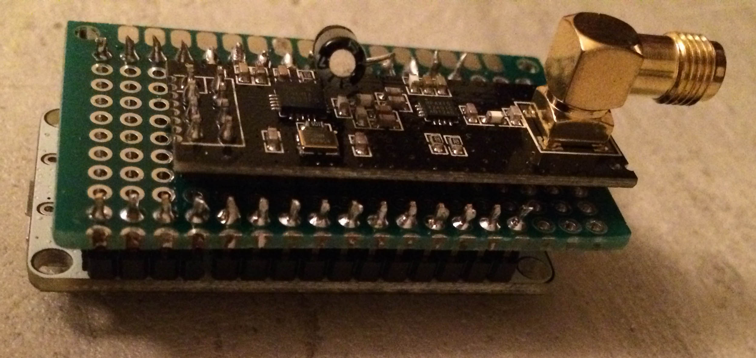
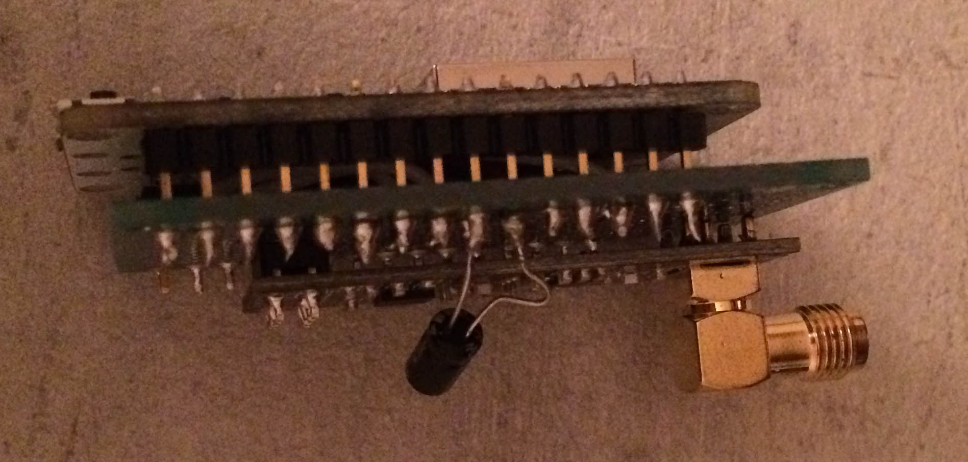
My Gateway is a ESP8266 with a NRF24L01+PA+LNA
First I cut one of my Prototype PCB and then I soldered the NRF24L01.
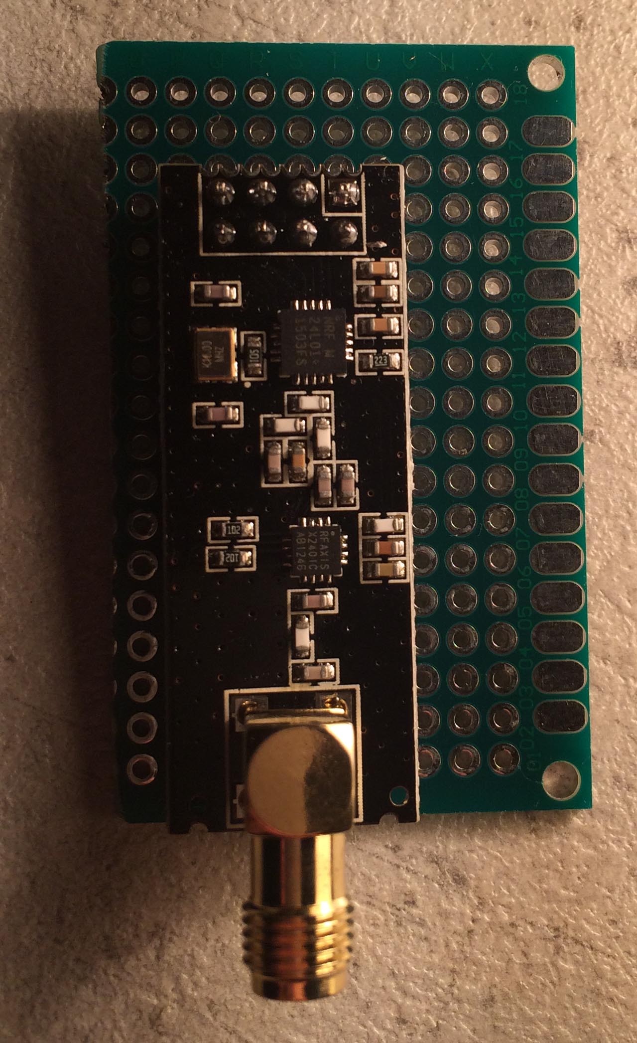
After that I started to prepare for all the cables.
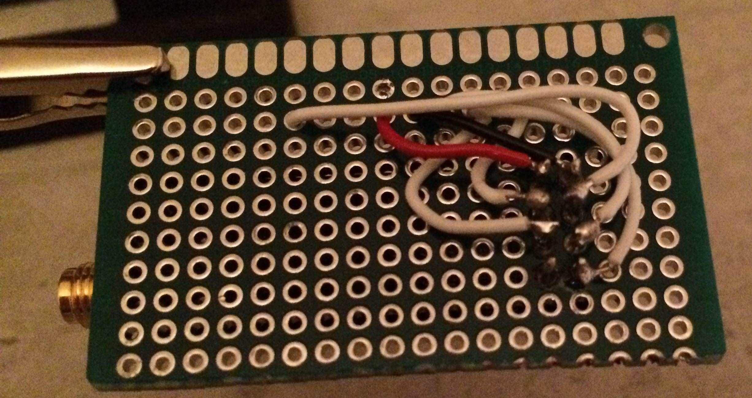
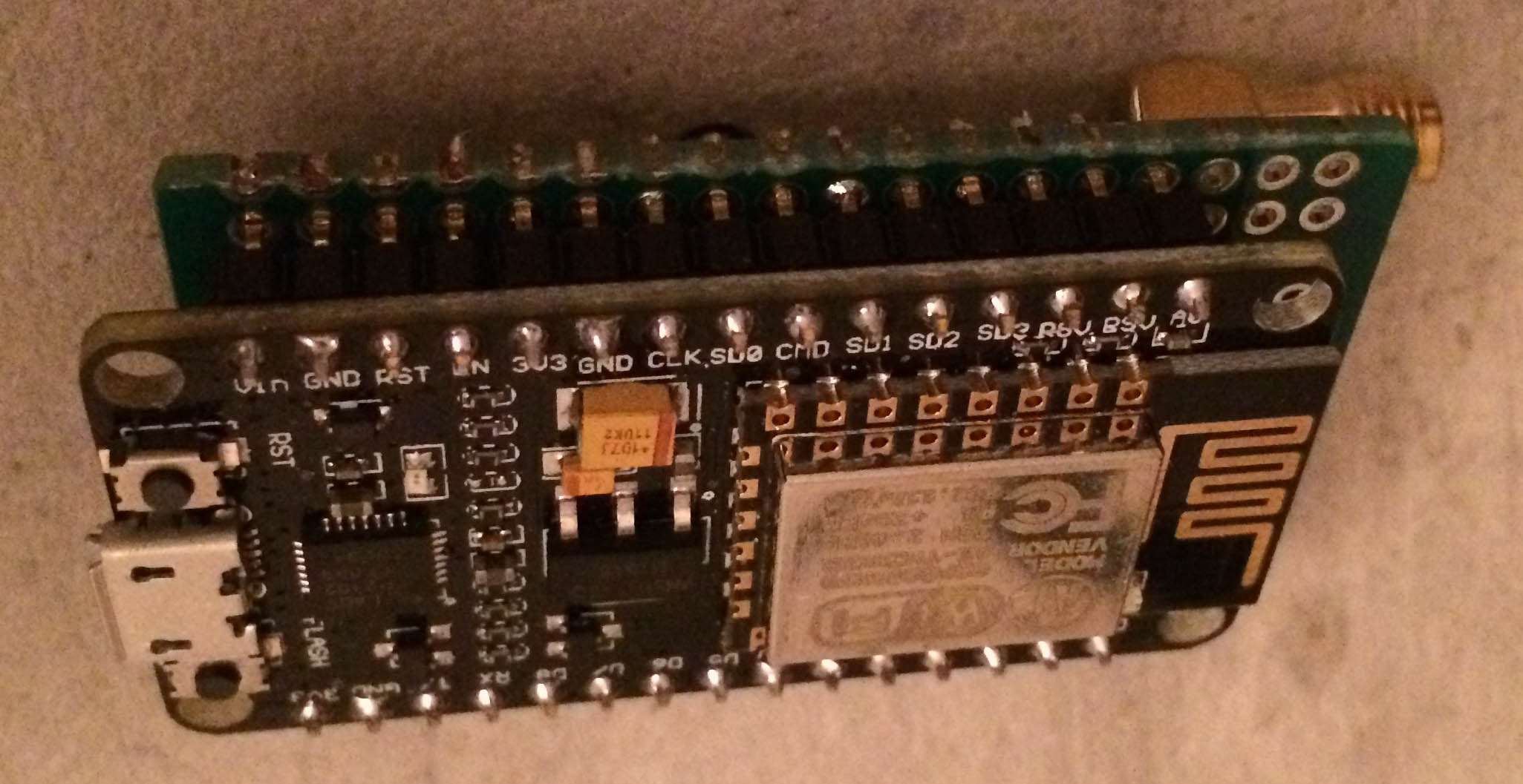
I finally put on the ESP8266 so it will hide the cables.
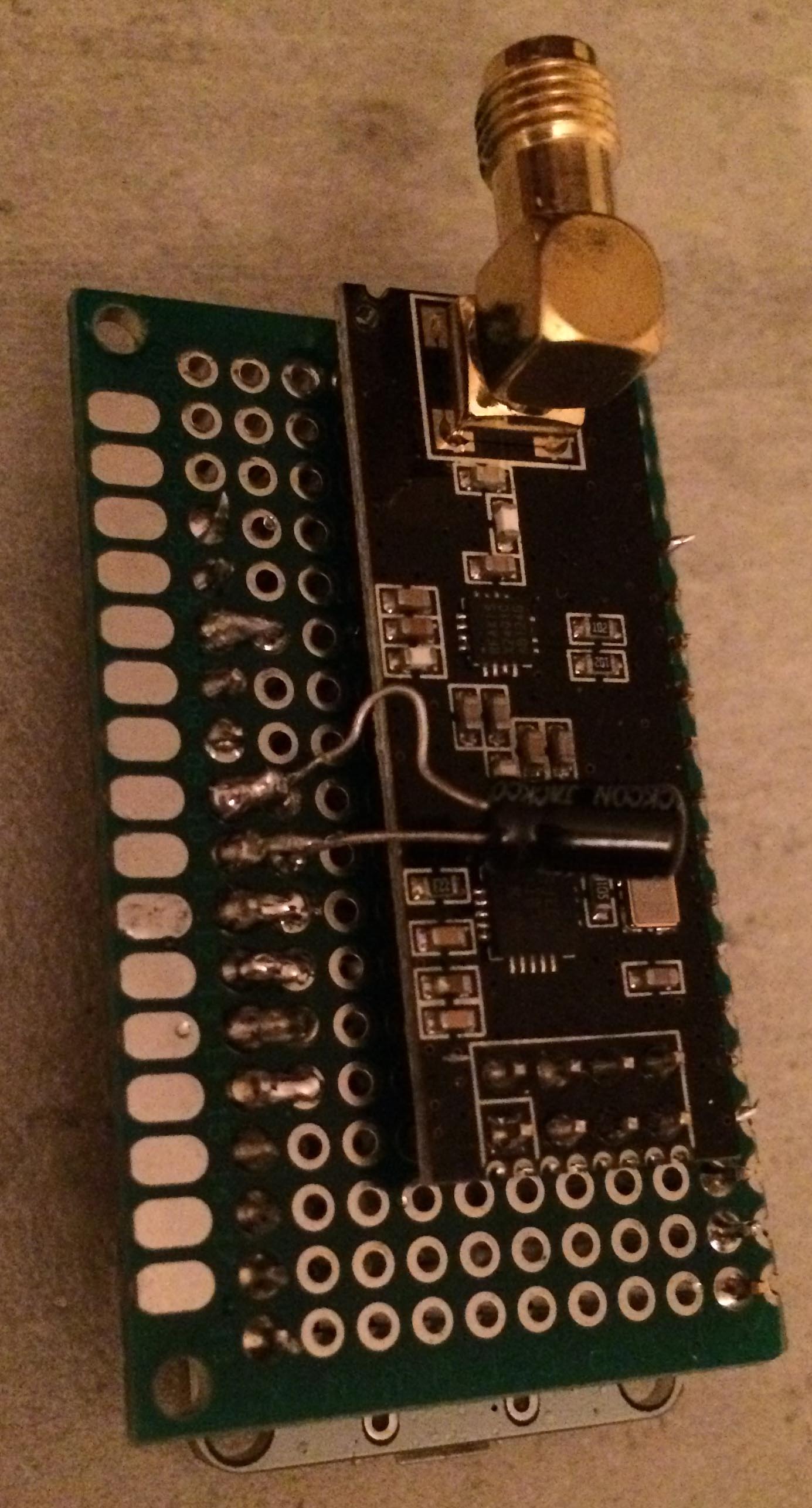
When it's done it looks like this:
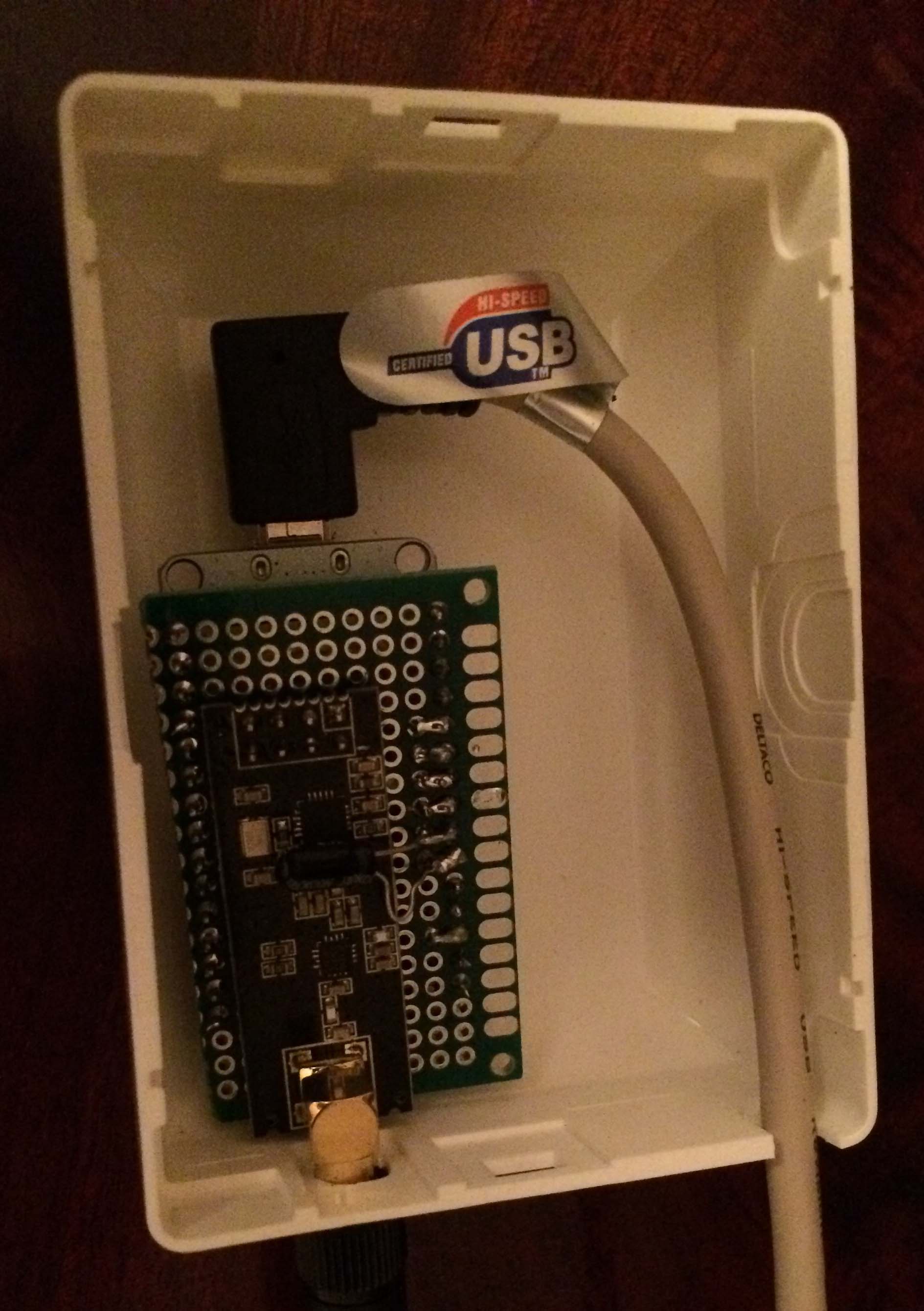
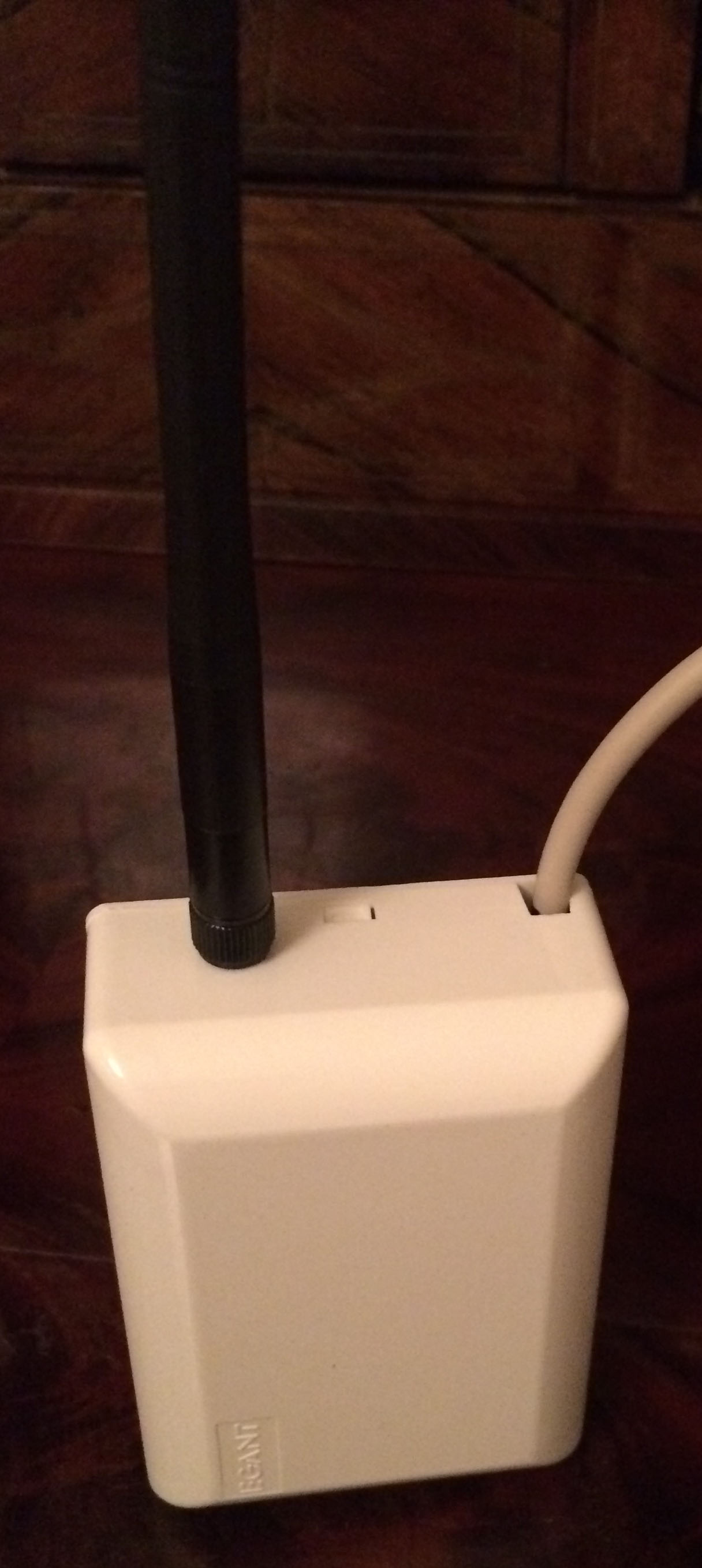
Here is when it's in a box. Yes, I know the box is bigger than it needs to be :)
-
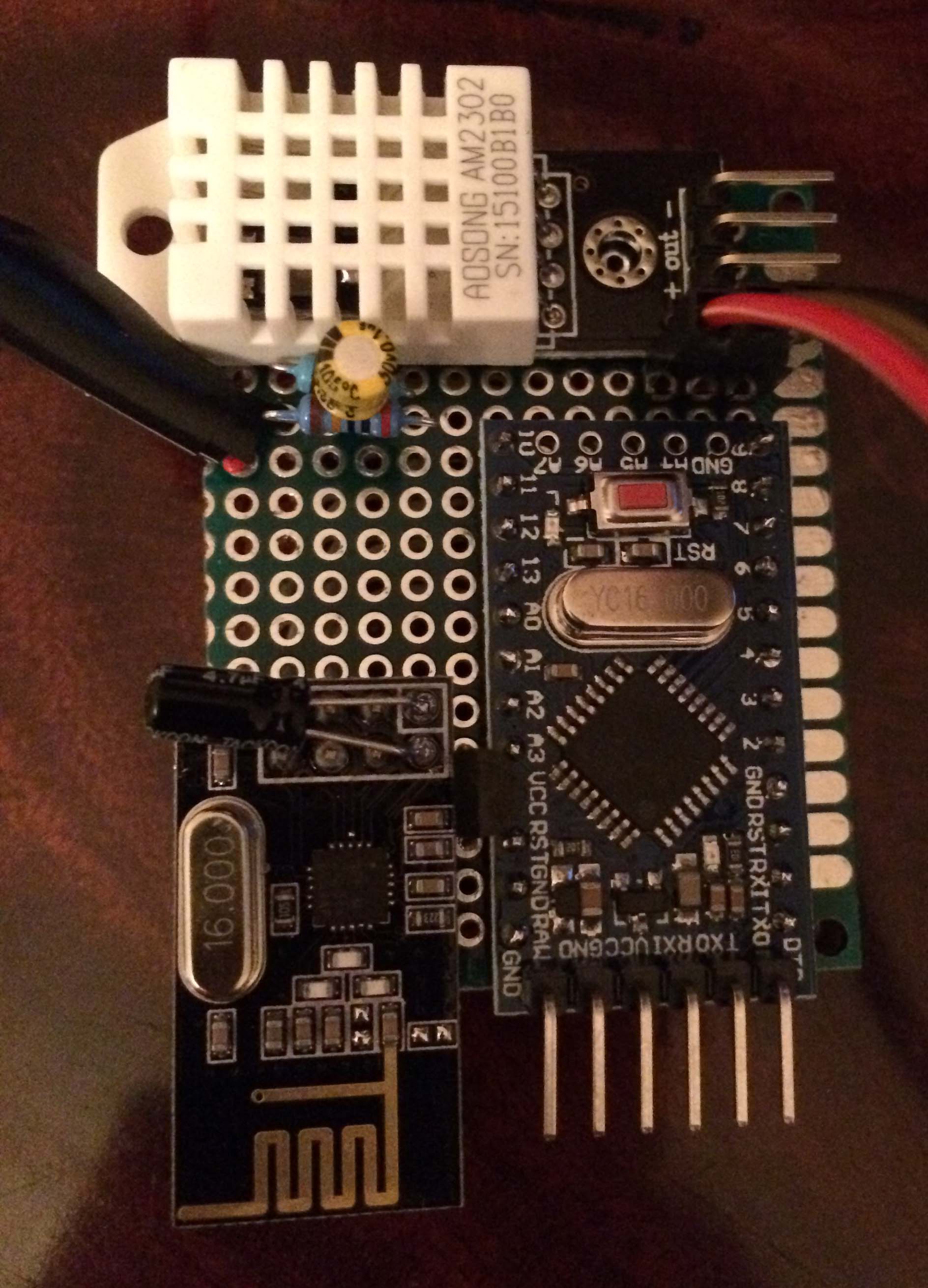
Here is my first node.
I got my inspiration from @the-cosmic-gate:s 3 in 1 incl battery monitorI am using a Arduino Pro Mini 5v because i have not recived my Step Up Boost Module 5V yet.
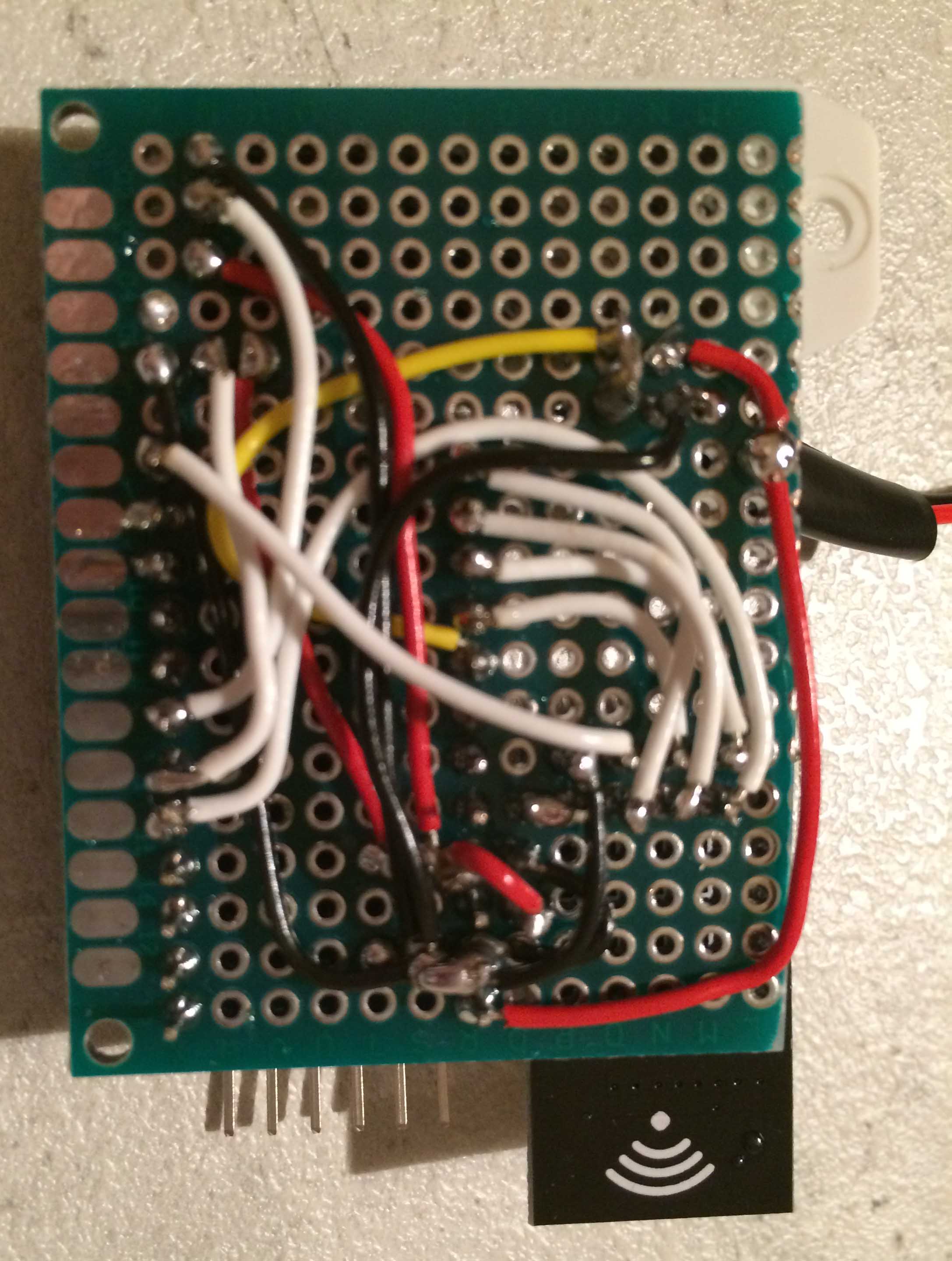
The sensors i have connect is a DHT-22 and a HC-SR501 motion sensor.This is the top.
This is the botton.
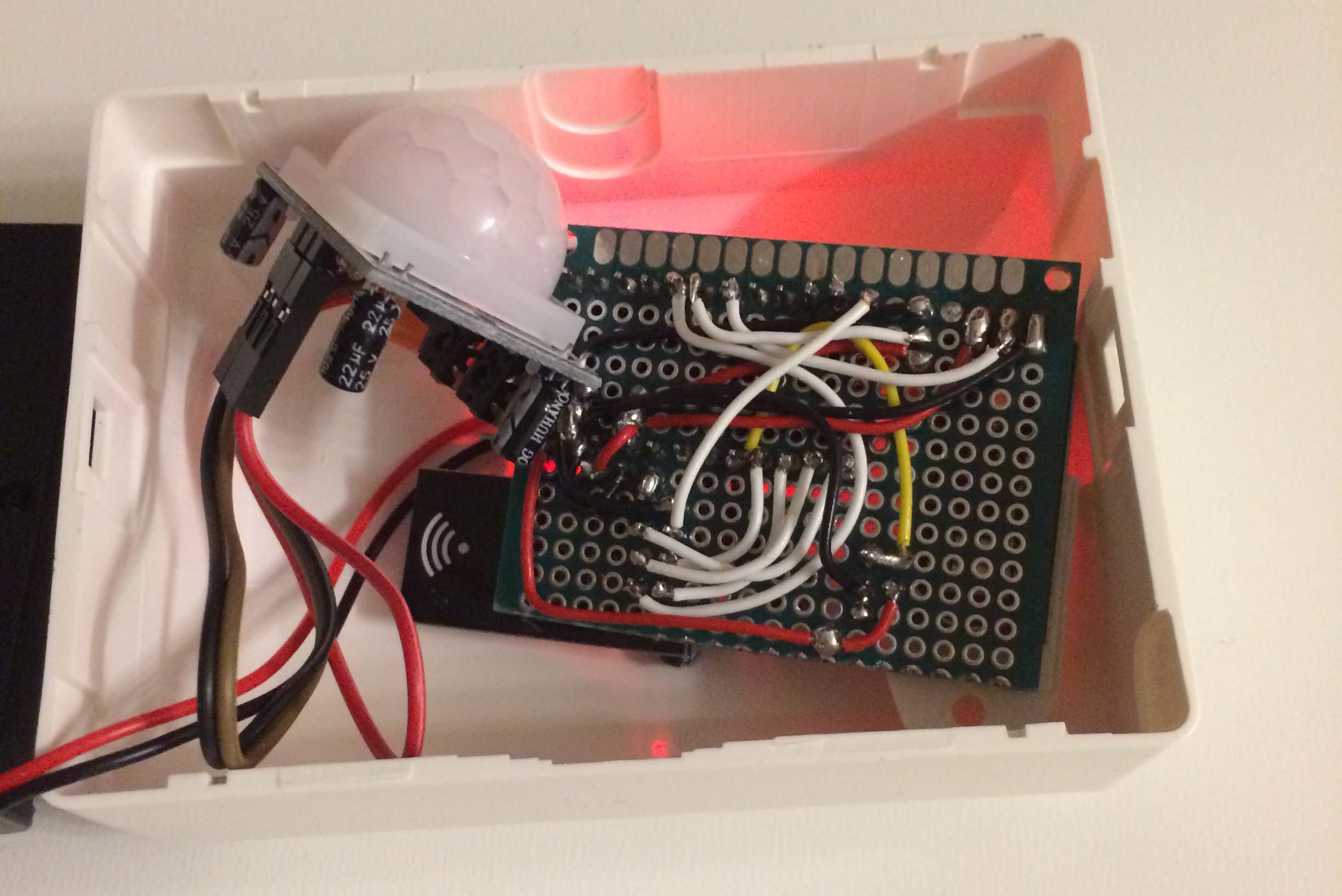
The box i use for this i the same i used for my gateway.
I will make a update when i have build my next node with a PCB from @sundberg84
-
@Dimitri-Henning It's from a store in Sweden.
http://www.biltema.se/sv/Bygg/El/Fast-installation/Kulodosa-2000022310/ -
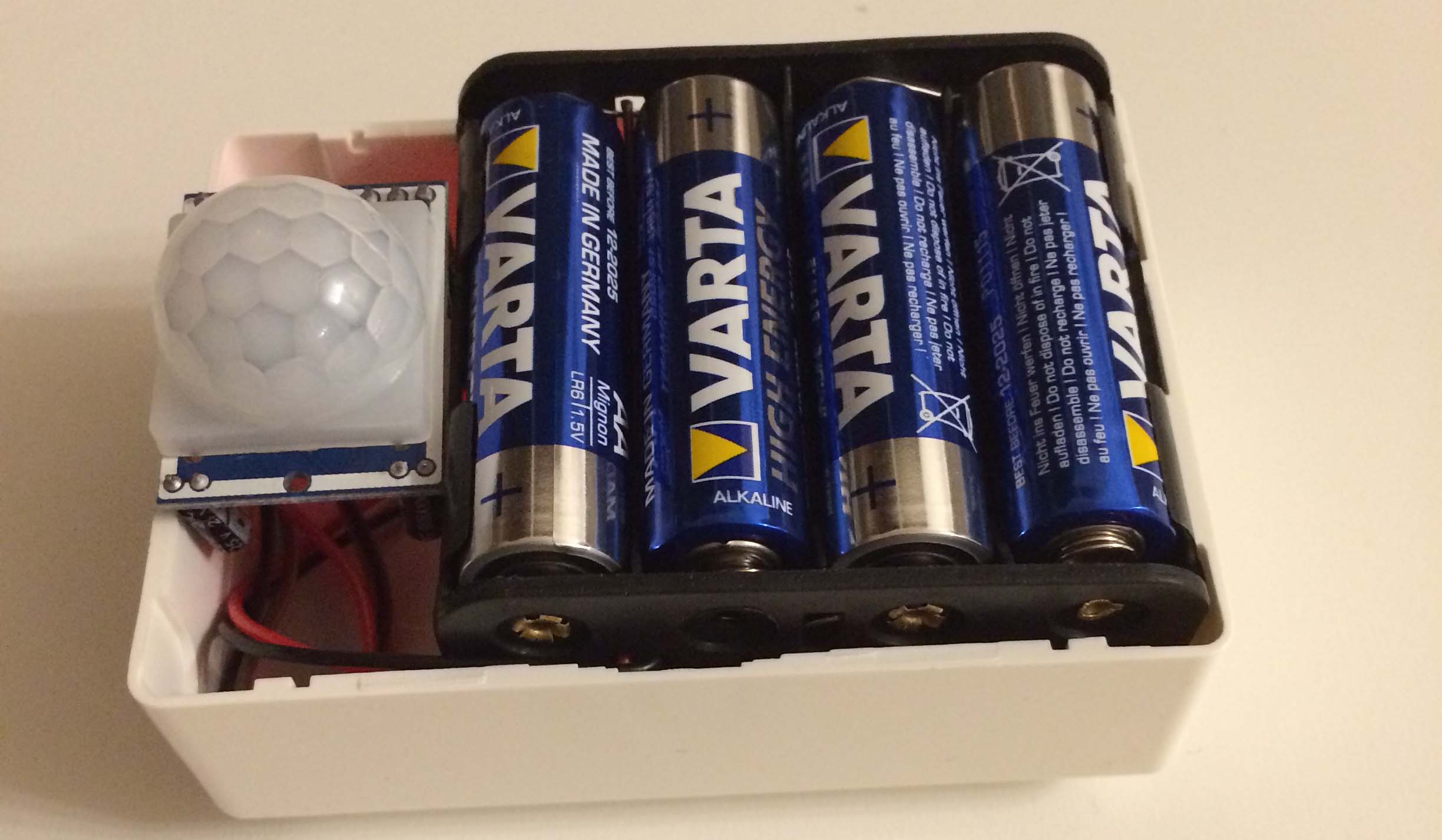
Yea, so do I! They are perfect because they fit a AA battery case inside perfect!
-
Nice that other have the same boxes.
They are good and cheep :) -
Today i got the PCB that i order from @sundberg84 design.
I orderd them from http://smart-prototyping.com/
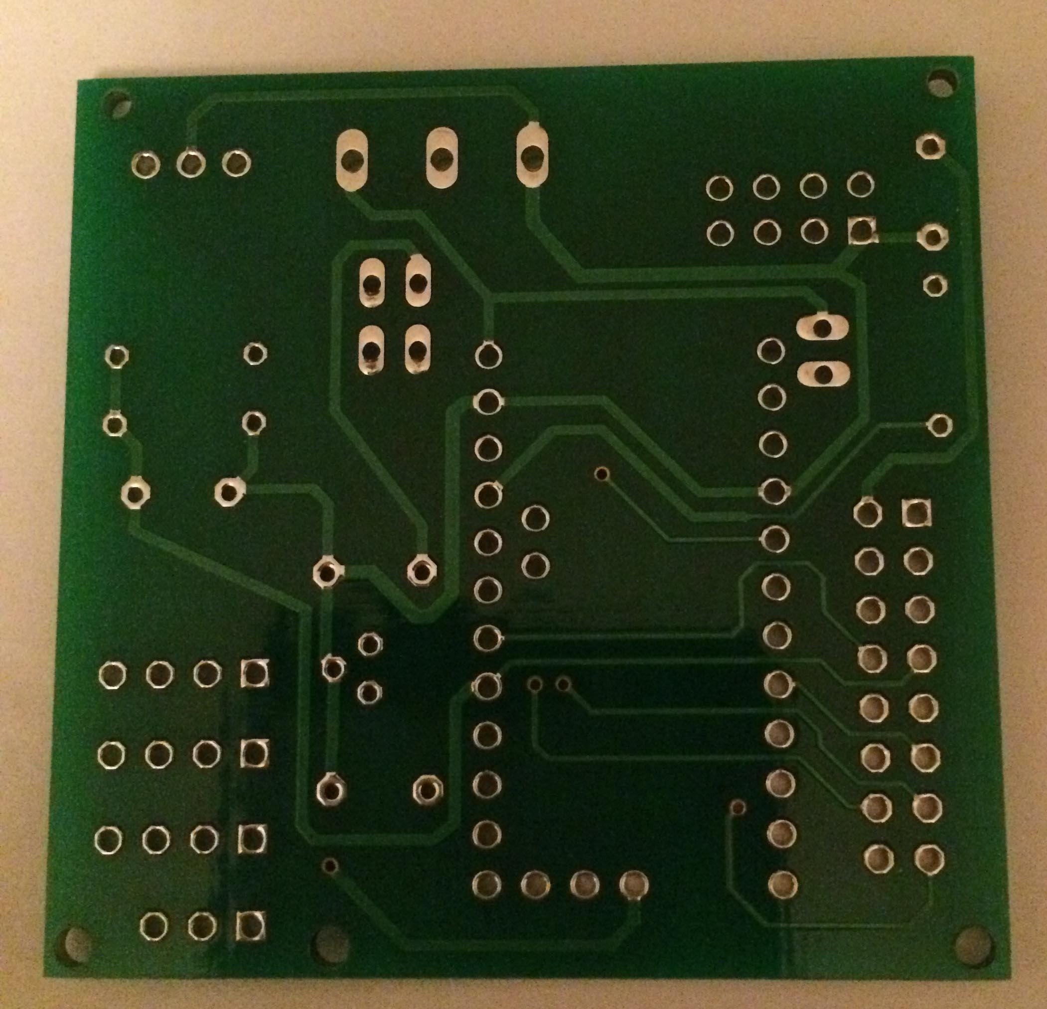
Here is how they looks.
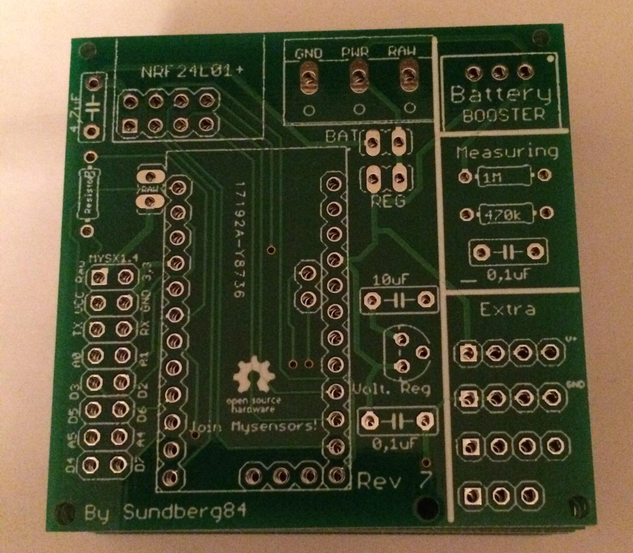
Will begin with my next node tomorrow.
In the waitng for the delivery i started to solder the pins on the arduino.
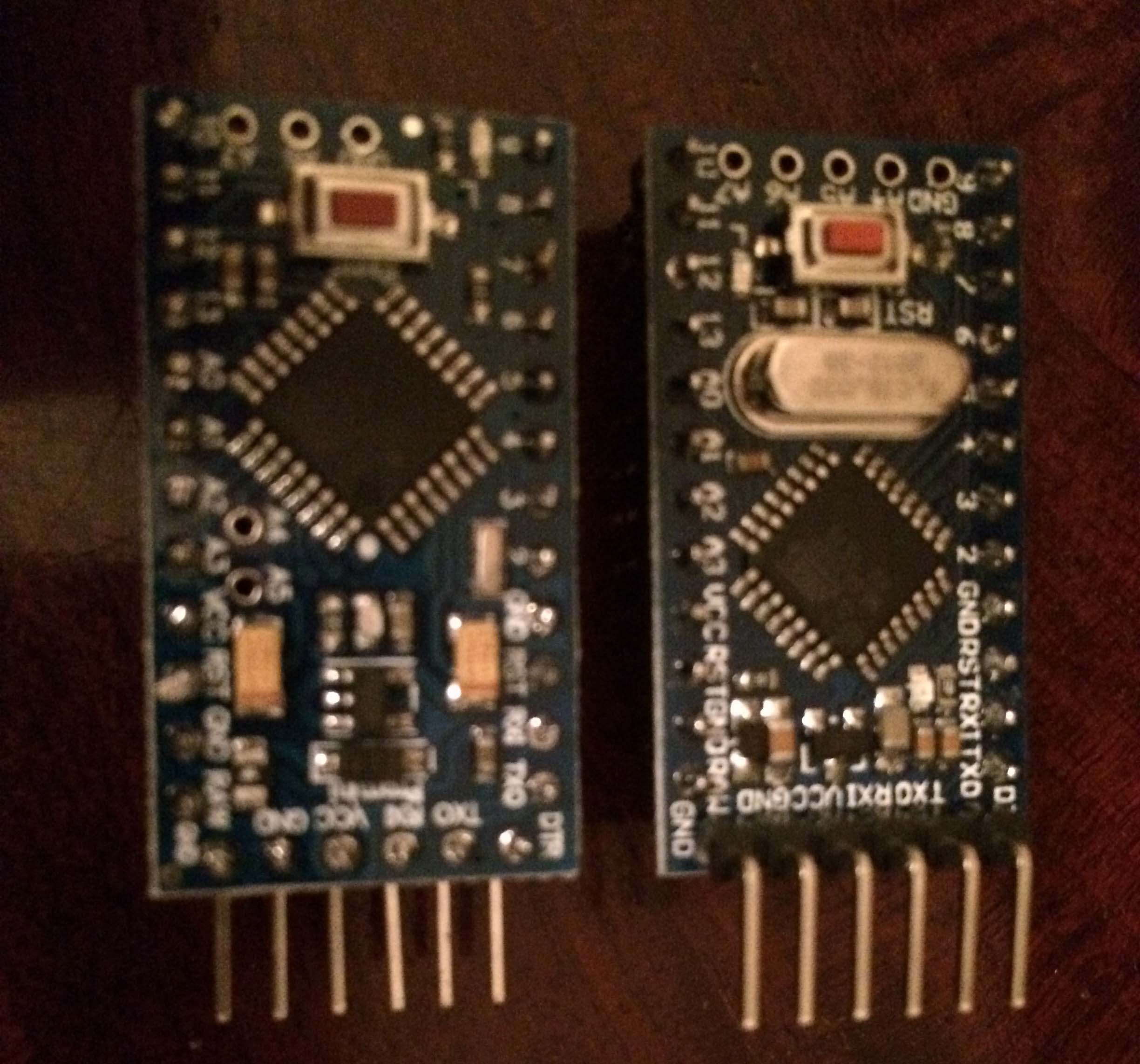
But i just find that it will not work with the PCB because the pins will then hit the NRF24L01.
So i need to start with unsolder them. -
Just turn them around or don't solder them at all and use the pins on the cable instead. ☺ good luck. Also don't power the node through fdti. The pcb is build to be powered through the pcb gnd/vcc/raw
Controller: Proxmox VM - Home Assistant
MySensors GW: Arduino Uno - W5100 Ethernet, Gw Shield Nrf24l01+ 2,4Ghz
MySensors GW: Arduino Uno - Gw Shield RFM69, 433mhz
RFLink GW - Arduino Mega + RFLink Shield, 433mhz -
Just turn them around or don't solder them at all and use the pins on the cable instead. ☺ good luck. Also don't power the node through fdti. The pcb is build to be powered through the pcb gnd/vcc/raw
@sundberg84 Thanks for the explanation. I will try that tonight.
-
My first node stoped a few days ago, it was working for 14 days on 4 AA (its a 5v Arduino).
I forgot to add the Step Up Module 1-5V to 5V. So now it's up and running again.
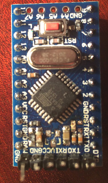
Now i will try to do some modifications to save power. I have been looking at the guide General Tips for Battery Operationt but i don't find where i shuld do the cutting/desoldering on my board.
Here is it.
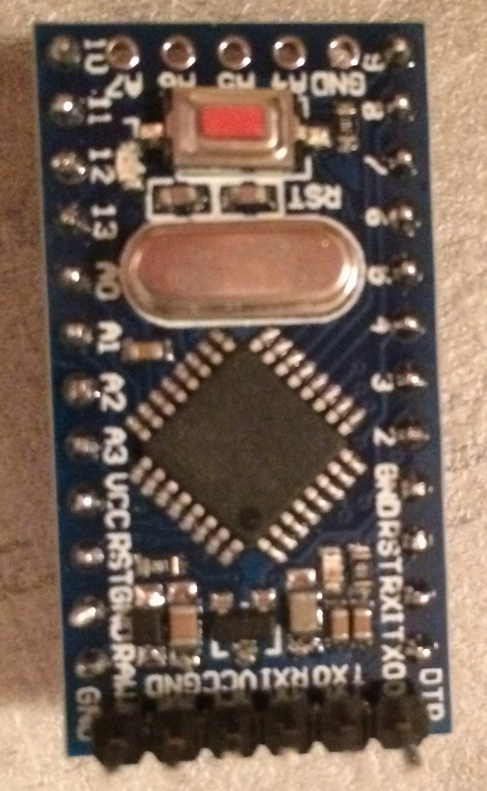
To know if i did the modifications right i want to measure the power with a multimeter, but i don't know how.
-
My first node stoped a few days ago, it was working for 14 days on 4 AA (its a 5v Arduino).
I forgot to add the Step Up Module 1-5V to 5V. So now it's up and running again.
Now i will try to do some modifications to save power. I have been looking at the guide General Tips for Battery Operationt but i don't find where i shuld do the cutting/desoldering on my board.
Here is it.
To know if i did the modifications right i want to measure the power with a multimeter, but i don't know how.
@ErrK the power led and voltage converter can be removed to reduce power usage. The led is on the bottom right in your picture (turns on when power is on) and the voltage converter is the small black rectangle with 3 legs on the bottom-center.
Instead of removing the LED you can also remove it's current limiting resistor, which is next to the LED, to the left of the t from 'rst' on the right of the board. -
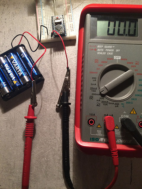
I think i measure right.
Here is how i do.
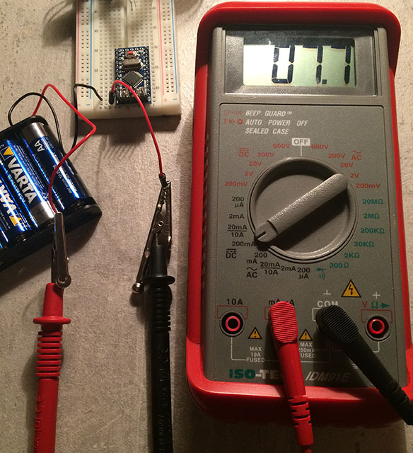
The led:s resistor is gone and the voltage converter is gone.
But now it don't start, did i do anything wrong?
Hello! It looks like you're interested in this conversation, but you don't have an account yet.
Getting fed up of having to scroll through the same posts each visit? When you register for an account, you'll always come back to exactly where you were before, and choose to be notified of new replies (either via email, or push notification). You'll also be able to save bookmarks and upvote posts to show your appreciation to other community members.
With your input, this post could be even better 💗
Register Login