110v-230v AC to Mysensors PCB board


  • A question about the fuses. The BOM in the Word document links to two 230V fuses, the PTC and slow blow fuse. If I read the schematic correctly one fuse is on the AC side and one is on the DC side. How does a 230V fuse help on the DC side where there should not be more than 5Vdc? Or am I missing something? As I'm quite new to this I'm probably not reading the schematic correctly or missing something 🙂


  • @aproxx said:

    For those who wanted to see some pictures of the board:
    IMG_20150921_194059 (Small).jpg IMG_20150921_194039 (Small).jpg IMG_20150921_194035 (Small).jpg IMG_20150921_194023 (Small).jpg IMG_20150921_192748 (Small).jpg IMG_20150921_192737 (Small).jpg IMG_20150921_192728 (Small).jpg

    Small notice: These pictures are of a slightly older design. The newer design has a few minor changes like better component placement and a permanent fuse instead of this resettable fuse. But these pictures should at least give you an idea on how everything looks like, and shows how really small it actually is.
    Also, I reinforced the traces of the 230v lines, which I absolutely recommend to do! (Although I do recommend to do it slightly more professional than I did on this prototype :))

    I really like this design, but it would be even nicer when this fits a ESP8266 🙂 Maybe the PCB could be even smaller . And it works together with link text .
    So is there maybe one of the PCB designer guys who can build /draw / design this 230v to ESP8266 PCB ?


  • WOW, REALLY GREAT JOB!


  • Hello everyone,

    This is a gr8 project, i am looking forward to make few sensor for my home. As i don't have any experience with electronics and very new to all these terms and components.
    I would request anyone of you to, kindly post some pictures of the board with components in place that i can copy and make my boards.
    **Specially 3 pin regulator and Capacitors **

    My first assembled board is not working, it looks like m doing something wrong with either the capacitors or the regulator. I checked my NRF24l01 VCC pin and not getting any voltage at all.

    Please help me guys......

    Thanks and Regards
    Brij


  • Mod

    @Brijesh-Mishra said:

    I would request anyone of you to, kindly post some pictures of the board with components in place that i can copy and make my boards.

    @the-cosmic-gate has already posted images above.

    Perhaps you should post a picture of what you've done?


  • FullSizeRender 7.jpg FullSizeRender 6.jpg FullSizeRender 8.jpg

    Thanks a lot for your response, this is what i have done so far.


  • Could I ask to the smart PCB builder's / designers to make the same 230v PCB but not using an Arduino but one of the ESP8266 versions , the the board could be even smaller and easier to fix in the wholes


  • @the-cosmic-gate, greetings to you. Kindly let me know, is there any issue with the component placement in the board. Not sure why it's not working :(.

    Thanks
    Brijesh


  • @aproxx Great job. Just started to work with mysensors and I was looking for a power supply alternative to mobile phone chargers. Though one question; the board that you included the relay was really interesting. Why did you not proceed on this? Also, do you sell the PCB's?


  • @Brijesh-Mishra said:

    @the-cosmic-gate, greetings to you. Kindly let me know, is there any issue with the component placement in the board. Not sure why it's not working :(.

    Thanks

    Brijesh

    There absolutely nothing wrong, but I want to use the ESP8266 to build in instead of the arduino and 2.4 ghz radio (the ESP8266 is an Arduino incl WiFi) so the PCB can be much smaller I think.


  • @Brijesh-Mishra , I see two issues with your photos. 1) the 3.3V regulator is on backwards. If you earlier in this thread someone comments that the regulator needs to be put on backward. The white design on the board is not correct. That was also my experience with the boards I built. The flat side of the regulator should face the two cap's. 2) more importantly, it appears that you used a thermal fuse in the spot where fuse #1 goes. Fuse #1 is supposed to be a 300ma slo blow fuse. If that is what you have there no problem, but it looks like the thermal discussed in the thread. This board does not have a place for the thermal fuse. I would consider this a serious safety issue, but I am not an expert. Hope this helps.


  • @novicit, Thanks a lot for your help. i will make a new board as per your guidance and share the photos soon.

    Regards
    Brijesh


  • 1.jpg 2.jpg 3.jpg 4.jpg

    Hello. Here I soldered all works well. Thank you


  • Hi @vampircik,

    Can you please share roughly how much it costed you to build that node?

    Thanks


  • Hi,

    I now received PCBs from DirtyPCB. I'm searching components (but not from China sellers).
    Can I use this varistor on the AC side?: http://uk.farnell.com/multicomp/mcsr391k10ds/varistor-60j-250vrms/dp/1856880
    And on the DC side?: http://uk.farnell.com/multicomp/mcvz1206m050agt/varistor-multilayer-4vac-0402/dp/2462756

    Thanks in advance!


  • I can not help.I not particularly versed in radio details


  • @aproxx hi wonderful design , i was going to make a similar but i can't find EAGLE part and footprint
    for HLK-PM01 ,and actually i don't know how to design the part library .
    so please if you can share it i will be thankful


  • Hardware Contributor


  • This post is deleted!


  • I really like that this uses the hlk power supply. Any versions of this floating around that instead of a relay do a digital/analog pinout for you to connect sensors to? That would be like a plain vanilla do anything board with safe power


  • Hardware Contributor

    @punter9 check our hardware site openhardware.io


  • thanks! one more question. I am really striking out finding resettable fuses for 120v US application. Anybody conquer this mole hill?


  • Admin

    @punter9 said:

    thanks! one more question. I am really striking out finding resettable fuses for 120v US application. Anybody conquer this mole hill?

    I don't remember where I read this but it was advised not to use resettable fuses with the HLK. Basically it was said that if the fuse were to blow the HLK would have already been stressed to the point where it may be unsafe and it's best to replace the whole device. I wish I could remember where I read that but I'm not sure...


  • Hardware Contributor

    @petewill said:

    I don't remember where I read this but it was advised not to use resettable fuses with the HLK. Basically it was said that if the fuse were to blow the HLK would have already been stressed to the point where it may be unsafe and it's best to replace the whole device. I wish I could remember where I read that but I'm not sure...

    I'm 90% certain that was from the guy who did the power tests of the HLK. I believe he was saying that these small PSU's don't handle heat or spikes well and if the fuse goes, you should assume the PSU is unsafe as well and replace it. I think it was in a thread that he was replying to on a different forum but I could be wrong.


  • @TD22057 said:

    @petewill said:

    I don't remember where I read this but it was advised not to use resettable fuses with the HLK. Basically it was said that if the fuse were to blow the HLK would have already been stressed to the point where it may be unsafe and it's best to replace the whole device. I wish I could remember where I read that but I'm not sure...

    I'm 90% certain that was from the guy who did the power tests of the HLK. I believe he was saying that these small PSU's don't handle heat or spikes well and if the fuse goes, you should assume the PSU is unsafe as well and replace it.

    Here it is I guess: http://lygte-info.dk/review/Power Mains to 5V 0.6A Hi-Link HLK-PM01 UK.html

    Quote: "I would place a fuse or fusible resistor before the converter, the fuse is not supposed to be replaceable, when it blows it is time to replace the converter."


  • @HenryWhite it mean that appart if you make a direct shortcut with a metal part, the only thing that came make the fuse blow, it is because of the HLK part.
    So: fuse blow = HLK dead.
    HLK dead = you don't need a resettable fuse, as you have to unsolder the HLK to repair the board (if no component seam to be dead after this one).


  • Hi and thanks for sharing your project!!! I'm new here and up to now I've been using Fritzing as PCB design tool. I'm impressed with the 3D preview of diptrace. I've imported your project since is almost what I need, but I need some changes: ESP8266 (E-12/E-04) instead or Arduino and Relay instead of SSR.

    When I import your project I can't see 3D preview of HLK. How do I import this 3D part? Where's can I find the Songle Relay part that has been shown above?

    Just one more question: why do you use NRF24L01 + Arduino if you can do the same and more with ESP8266?? :o/

    Thanks again and best regads!!!

    P.S.

    I'll share my PCB if you wish.


  • @aproxx said:

    Hi all,

    After spending a few months on this forum and a few prototypes later, I decided I wanted to build a small but cheap PCB which could be placed in either the wall behind the light switch, or above the lamp.

    Besides the boards I've seen on this forum, I wanted these boards to contain a module to go from 230v AC to 5/3.3v DC in order to power an Arduino nano and the NRF module. I eventually ended up with a PCB which is about 4 by 4.5cm. So with all components attached I'm hoping to get in stuffed in a 5x5x3cm plastic printed case.

    Modules which I've used to power the board:
    [http://www.aliexpress.com/item/5-pcs-HLK-PM01-AC-DC-220V-to-5V-Step-Down-Power-Supply-Module-Intelligent-Household/32319202093.html?spm=2114.32010308.4.19.8oKfZg

    UPDATE: 2015/09/18
    As promised, I've got an update for this project. The board has been tested in the past week, and everything is working as expected. Compared to the previous board I've posted, I have updated the following:
    • Solder pads of LE33CZ have been placed a little wider apart to avoid short circuit while soldering.
    • Solder pads of the resettable fuse (Fuse2) has been placed closer together to better fit the fuses of the BOM.
    • Moved the NRF24L01 connector a bit away from the solid state relay. Should make it easier to solder.
    • Moved Fuse2 to another location on the board, away from the 230v circuit.

    Some 3D pictures (Top and bottom):
    Top.png
    Bottom.png

    Anyone who is interested can order the PCB HERE

    Some documentation, complete list of required components and all gerber / DipTrace files (in case you would like to make some modifications) can be found here: MySensors board v3.2.3.zip.


  • Just ordered 10 pcs of this board. Great Job!


  • thanks for the update on the resettable fuses! Another rookie ?. I ordered 0.4A fuses since the 0.3A are sold out. Is this a classic dumb move thinking that 0.1A is no big deal?


  • Hardware Contributor

    HLK spec. is max input of 0.2a with small spikes tolerance to 1.0A. I also ran out of 0.3 but are now using 0.2a and that works fine.


  • Does the light switch need to be a SPST or can you use a pushbutton? Curious how this would work with a SPST switch. I haven't looked at the code to see what is setup.


  • @csa02221862 said:

    SPST

    This depends on the sketch you flash. 😉


  • Hi,

    I understand that the question has already been asked, but ... Is there a possibility to adjust the scheme to the ESP8266 instead of Arduino? Anybody can tell or help - how to do it?

    Regards,
    Nikolay


  • yes, now how to use ESP8266 instead of arduino for the same function that we are discuss in this topics.


  • Hey Guys,
    I am working on ESP8266 as well. But I am newbie to electronic designs. But in my view it should be silmple and we can replace Arduino nano with ESP8266 and remove NRF module.

    One diagram and circuit is explained here http://iot-playground.com/blog/2-uncategorised/77-esp8266-internet-controlled-switch-easyiot-cloud-mqtt-api#materials

    @csa02221862 you can use this cercuit with SPST buttons. But Switch will notbe connected to mains. It will be conneted to ESP8266 GPIO of (or arduino). And in Sketch (i.e code ) you have to write code based on GPIO when ever it goes 0 to 1 or 1 to 0 Relay state shoud be toggled.

    I hope I make sense

    @aproxx you did great job here.

    I am looking to reduce its size more if possible and wish to use ESP8266. Also looking to add more then one relays to the board. In some rooms there are 3 buttons on one panel. So thinking to use 3 relays. Will it be a good Idea? I think should not matter as long as I have enough GPIO to control relays and Electric wire connectors can bear the load.


  • yes , I also thinking to use more than one relay.


  • Hardware Contributor

    Found something interesting on Aliexpress which is a drop in replacement for the HLK-PM01:

    the HLK-PM03

    Same size and pin locations, but 110-200 V AC to 3V3 DC.

    0_1455218529807_IMG_7765.jpg

    http://www.aliexpress.com/item/5-pcs-HLK-PM03-AC-DC-220V-to-3-3V-Step-Down-Buck-Power-Supply-Module/32585760937.html

    It fits my multi-power options board perfectly.


  • Nice find GertSanders ... I am planning to use esp8266 which runs on 3.3 volt... best fit ..

    If we use this we may have to drop few things from 5.5 board right?
    Like no need of 5v - 3.3 converter
    change relay to match 3.3v like this http://vod.ebay.com/vod/FetchOrderDetails?qu=1&itemid=401045943120&transid=522355020027&viewpaymentstatus=

    Anyexpert around? do we need to remove anythingelse (any capacitor?)


  • But 3.3v relay will not match the board. If we use 5.5v relay do we need to add something to circuit?


  • Hi,

    Thank you for this pcb. In which program did you do the design? Do you think you can share an editable version of the design?

    I would like to modify it to accept the Mean Well IRM-05-5 instead of the Hi-Link.
    It is more expensive and bigger AC-DC circuit but since I hace some in my stash i would like to use them.


  • Mod

    @toabhishekverma said:

    change relay to match 3.3v like this http://vod.ebay.com/vod/FetchOrderDetails?qu=1&itemid=401045943120&transid=522355020027&viewpaymentstatus=

    That's a link to your shopping cart, we don't have access to...
    I'm interested in the relay, can you post a working link?


  • oops..

    here is the link

    http://www.ebay.com/itm/401045943120


  • Hardware Contributor


  • @GertSanders thanks for this link.
    So do you have working prototype? what board are you using? I am in middle of finalising components and trying to finalise design. With little knowledge of electronics my progress is slow.
    Also for 220 to 3.3v there is another converter from Olimex https://www.olimex.com/Products/Power/PWR-90-240V-3.3V0.8A/
    overall its abit smaller then Hi-Link... Hi-Link abit better because all covered and less dangerous.

    Please share if you have any design finalised.


  • Mod

    @GertSanders @toabhishekverma Do you have the dimensions and/or holding resistance?


  • Sorry I didnt get your questions .. do you mean dimensions of 220-3.3v converter. Here they are.
    output 2.5W 3.3V/0.8A +-0.2V size: 30x20x18mm

    I am not from electronics background so didn't get what holding resistance means?


  • Mod

    @toabhishekverma No, I meant for the relay 😉
    What's the resistance of the 3V coil? I want to know the current flowing when the relay is active.


  • @Yveaux Still no idea about it. Check link if you get something from it. what I know is it can bear up to 10A current and can be controlled using 3v .... my order still in shipping so don't know more then that.


  • Mod

    @toabhishekverma Ah, ok. Didn't know they were still in transit.
    Maybe @GertSanders has them 'on stock'?


  • Mod

    @HenryWhite Awesome! Didn't even think of looking for a datasheet of a Chinese relay 😉


  • Another source :

    50Pieces/Lot JRC-21F 4100 3V DC 6 Pins Miniature PCB Relay Brand New
    http://s.aliexpress.com/MNVv2myE


  • Hardware Contributor

    @Yveaux No, also still waiting for the order to arrive. But a coil resistance of 20-25 Ohm means driving the coil with a FET. Not directly from a atmega328 pin.


  • Hardware Contributor

    @Porky6666 : only switches 3A, SONGLE relay can switch 10A.


  • @GertSanders said:

    @Yveaux No, also still waiting for the order to arrive. But a coil resistance of 20-25 Ohm means driving the coil with a FET. Not directly from a atmega328 pin.

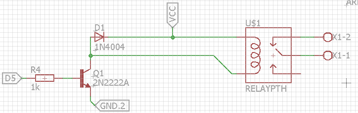
    Correct. Here's how I wired the songle relay on my Lithium Ion Sensor PCB:

    0_1455277788002_123123.png

    @GertSanders said:

    @Porky6666 : only switches 3A, SONGLE relay can switch 10A.

    I wouldn't trust both of them when it comes to switching high amp devices over 3A. I think there is a reason no german electronics shop sells songle relays 😄

    Plus, relays from an electronics shop in your country might cost the same than the songle relays or will just be a tiny bit more expensive.

    At least this is true for 5V relays. 3V relays are hard to find (at least in germany)


  • Hardware Contributor

    @HenryWhite said:

    I wouldn't trust both of them when it comes to switching high amp devices over 3A.

    I agree, I plan to switch lights, so my preference goes to the 10A model, just to be sure. I have used the SONGLE 5V versions, and none have ever given me reason to doubt their quality. Since I found a 3V3 powersupply I want to try building a full 3V3 board. Should be fun.


  • @HenryWhite why do we need D1 Diode (if i am write) in that circuit? do this circuit will not work without diode?
    (sorry dont know much about electronics)


  • @toabhishekverma https://en.m.wikipedia.org/wiki/Flyback_diode

    in short: It is needed to protect the NPN transistor from damage.
    The circuit will work without diode, But eventually damage the transistor.


  • Hardware Contributor

    @GertSanders Have you breadboarded your 3.3V design? I'm a bit worried that removing linear converter will impair the performance of the our fussy nRF clones due to less power supply ripple rejection. I think those going for the ESP8266 are better off.


  • Anyone has an idea where to source the 5.5V varistor? I received a bunch from AliExpress following which seem to be broken.
    I found this link http://www.farnell.com/datasheets/575651.pdf. However, there seem to be a bunch of 5.5 V varistor. Can anybody help me figuring out the right ones?


  • Hardware Contributor

    @m26872 I have not used the 3V3 version of the Hilink converter, it was just shipped today (ordered last week). It will take a few more weeks to reach me. But then I will test it on my ac board. We will see.
    23/FEB: Update: the converters are here. I will make a node with this converter version this weekend.


  • @icebob said:

    @tomkxy I'm using this one: http://hu.farnell.com/multicomp/mcvz1206m050agt/varistor-multilayer-4vac-0402/dp/2462756

    Thanks! It's a pity that the chinese "varistors" seem to be jumpers. I even saw in some offers on AliExpress that they are referred to as jumpers.


  • How can I check whether the solid state relay works at all. My assembled board receives messages and sets state properly, I have 5V on the pin, however the relay does not seem to switch. Should I hear it? Any other ideas for "debugging"?


  • Hardware Contributor

    @tomkxy
    Measure the resistance over the AC terminals of the SSR. It should be very high when "open" en very low when "closed". SSRs do not make sounds when they switch, so sound will not give a clue if they work.


  • Most SSRs cannot be checked this way because they can only switch AC and not DC. See https://en.wikipedia.org/wiki/Zero_cross_circuit


  • I don't know if this has been answered already. But I have some major problems soldering the thermal fuse to the board. It always blows. Any tips ?


  • Hardware Contributor

    @Cliff-Karlsson Be quick 🙂
    I have the same problem - dont know any better sollution atm... solder for 0.5 sec and remove - then you need to let it cool down before adding more solder.


  • I read something before about low temp thermal sensors usally being crimped to place. Do you know how this works and if it is usable on the pcb?

    Also the last times I tried to assemble the parts on the pcb I noticed that the holes for one of the fuses are too narrow for the standard brown(?) auto reset fuse. I have managed to destroy the solderpads every time I tried to drill the holes a little bigger.
    Can I use a standard glass fuse for this one with the same value?


  • Just a couple of questions. Most of the components are 240V, are these the same as used for 110/120v in the US? Also one of the varistors is not available, suggested alternative?
    Thanks


  • Hi,

    thanks for your great work..
    great to have chosed a pwm output for the relay (ssr can be used as a dimmer)
    but is it possible to add a fuse on the ssr output too ?
    and a second switch

    and imho relay's trace is too near a nrf trace..
    and return the draw of le33 😛

    sry for my english
    thanks


  • Hello,

    I love your design!
    However, I must have missed something. Considering I want to retain the ability to turn the light off with the wall switch, this board does not allow to connect the relay as a 3-way switch.

    Also, considering it could be mounted inside the wall (and not only in the lamp base) - having 2-3 relays would be very functional! In my house, it is very common that a single wall mount has 3-4 switches that control 3-4 separate lamps. It will probably make the board bigger, more so if we support 3-way switches (see above comment), but it will be very versatile, especially for 4-way switches (see http://forum.mysensors.org/topic/3173/3-4-way-switch-with-a-relay )


  • Hi Sefi Ninio,
    There are two ways you can do it, Either change relay to SPDT Relay which is two way relay. this option is not feasible with this pcb. But if you are not using same PCB you can try SPDT relays.

    Second option which can work with this setup is ,
    Your light switch has two pins, connect them with gpio and 3.3 power .
    when switch turn on/off gpio pin input goes high(when on) and low (when off).
    You have to write a code to monitor this gpio and if its state changes, you have to toggle the relay state.

    This is my idea, I havent tried it yet. and I am newbie too, Please comment.

    I hope I am clear enough

    Regards,
    Abhishek


  • Hi, @toabhishekverma
    Well, your suggestion might work, I am not sure a switch that is meant to be connected to 220v mains can be connected to the gpio pin.

    I think, adding an additional relay to the pcb and allowing them both to behave like a 3way switch will allow for maximum flexibility.

    1. It could control 2 separate lamps
    2. It could behave like 2 3-way switches
    3. It could behave like a single 4-way switch

    I would have done it myself, but I have no clue 😀


  • I have several lamps where I have done something similar. The bulbs are wireless wemo-bulbs and I have connected the wires behind the lampswitch so that the bulbs are always powered. The I have placed a battery powered arduino witch is connected to the wall switch pin3-gnd.
    Every time I flip the switch the arduino wakes up and the controller sends a toggle command using REST


  • Hardware Contributor

    @Cliff-Karlsson said:

    I don't know if this has been answered already. But I have some major problems soldering the thermal fuse to the board. It always blows. Any tips ?

    Raise the temperature of your soldering iron, and you'll be able to do it quicker with less propagating heat. You could also add some extra bend and length to the fuse legs.


  • @Sefi-Ninio said:

    Hi, @toabhishekverma
    Well, your suggestion might work, I am not sure a switch that is meant to be connected to 220v mains can be connected to the gpio pin.

    I think, adding an additional relay to the pcb and allowing them both to behave like a 3way switch will allow for maximum flexibility.

    1. It could control 2 separate lamps
    2. It could behave like 2 3-way switches
    3. It could behave like a single 4-way switch

    I would have done it myself, but I have no clue 😀

    @aproxx , what do you think about adding another relay (for a total of 2 on board) and making them 3-way?


  • Another question about the thermal fuse. I might be wrong on this, but I guess its purpose is to break the power if the HLK overheats. But If placed in the intended place would not the PCB need to be on fire to have the thermal fuse be warmed up to 73 deg C?


  • @Cliff-Karlsson said:

    Another question about the thermal fuse. I might be wrong on this, but I guess its purpose is to break the power if the HLK overheats. But If placed in the intended place would not the PCB need to be on fire to have the thermal fuse be warmed up to 73 deg C?

    I guess you're supposed to glue the thermal fuse to the hlk and run wires from this point to the designated footprint of the fuse on the pcb.


  • @Sefi-Ninio said:

    @Sefi-Ninio said:

    Hi, @toabhishekverma
    Well, your suggestion might work, I am not sure a switch that is meant to be connected to 220v mains can be connected to the gpio pin.

    I think, adding an additional relay to the pcb and allowing them both to behave like a 3way switch will allow for maximum flexibility.

    1. It could control 2 separate lamps
    2. It could behave like 2 3-way switches
    3. It could behave like a single 4-way switch

    I would have done it myself, but I have no clue 😀

    @aproxx , what do you think about adding another relay (for a total of 2 on board) and making them 3-way?

    OK Guys,
    I've decided to try and use the original V3.2.3 plans and add another relay to them (with your permission, @aproxx).

    The board will have to be a bit bigger, I will have to make room for another relay along side the existing one, and I will have to also make room for its connectors.
    Not a big problem, I think, as it is already very well designed and has a small footprint, but still.

    I need a bit of help from you guys, though - I am a complete noob when it comes to the wiring and electricity. I can handle the coding, no problem, but the electricity is very new to me.

    I am assuming that besides adding the second relay, no other components need to be added - no resistors, capacitors, varistors etc.
    Is my assumption correct?

    Thanks!


  • @Sefi-Ninio said:

    I am assuming that besides adding the second relay, no other components need to be added - no resistors, capacitors, varistors etc.
    Is my assumption correct?

    Thanks!

    You need at least a second transistor.


  • maybe a fuse to protect relay output.. ?
    and plz add a second switch, to control an other node or anything..


  • So basically, I should duplicate the current circuit for the new relay...


  • I am facing a little problem with the fuses. I am using these:

    230V AC: http://de.aliexpress.com/item/TRF250-300U-line-resettable-fuses-0-3A-300MA-250V-Tyco/32368739339.html?detailNewVersion=2

    5V DC: http://www.ebay.de/itm/321697892220?_trksid=p2057872.m2749.l2649&ssPageName=STRK%3AMEBIDX%3AIT

    When I connect the pcb to power the LED on the Arduino flashes and then the 500 mA Fuse in the 5V circuit dies. I am now using the 300 mA resetable Fuse for the 5V part as well, which seems to work without problems. How can it be, that the 500 mA fuse dies and the 300 mA fuse does not?


  • Jan Gatzke; chinese brand electronics... who knows what can happens....

    i ordered all stuff needed to make my pcb with maximun 4x4cms to use inside wall switches (like zwave fibaro modules). i will try to reduce that board by not using connectors and solder the cables directly etc..

    Something that i don't know is why use a varistor and fuse on secundary??? arduino already have an polyfuse PPTC Resetable fuse, and someting bad that happens with nrf24 will burn the 3.3V regulator.. its that varistor and fuse realy needed?


  • @aproxx hello. can i know how you rendered your PCB layout to 3D , if any tutorial it can guide me
    to achieve that .

    thanks


  • Hero Member

    Wow, this thread has been really active in the past few months! I'm sorry for my absence, but I kind of got dragged into other projects.. 🙂

    A new version of the board will be shared soon! Compared to the current board following changes have been made:

    • A second solid state relay has been added. This 2nd relay is optional, so if only 1 device needs to be controlled just 1 relay needs to be installed and everything will still work fine.
    • The board size has been increased just a little bit to fit this 2nd relay. Size is still 5x5cm only.
    • Some components have been moved in order to make it easier to solder them (This was a bit tricky on version 3.2.3 because some components were really close to each other).
    • Traces between the relays and the connectors are now 'open air'. So there is no mask on top of the traces. This way it is possible to reinforce the traces. By doing this it shouldn't be any problem to connect a 2A load to the board.
    • A temperature cut-off has been added to the board.
    • The varistor for the low voltage circuit has been removed because it's not really needed anymore with all the extra security measures on the high voltage side of the board.

    Currently this board is still on it's way from China, but as soon as I've received this board I'll share all the documentation and everything else which is needed on this forum! This will probably happen in 3-5 weeks from now, so stay tuned! 😉


  • Admin

    Great @approx, please consider to create it as new project over at openhardware.io, much easier to keep track of things (and a forum thread will be created automatically).


  • Hero Member

    @hek That sounds as a great idea. I'll share it on OpenHardware as soon as I have confirmed that everything works as expected!


  • @aproxx said:

    • The varistor for the low voltage circuit has been removed because it's not really needed anymore with all the extra security measures on the high voltage side of the board.

    exacly what i was talking about!👍


  • bad news 😕 then why have you fuse at home ? 400 000 V has security measures, why add more security ? it's juste our life, childs life !!
    do you know what is a "security transformer" ? the hlk-pm01 isn't one.


  • Hero Member

    @vil1driver said:

    bad news 😕 then why have you fuse at home ? 400 000 V has security measures, why add more security ? it's juste our life, childs life !!
    do you know what is a "security transformer" ? the hlk-pm01 isn't one.

    It's not that I think that security isn't important, but I believe that no security on the low voltage side is safer than having a false sense of security. As I've read above, lots of the low voltage fuses were not reliable. And that's one reason I dropped it in the newer design.

    All that aside: I never ever EVER intend to mount these boards on locations people can reach (unless they intend to). Everything is placed safely behind a light switch or in a completely closed plastic box. The only thing that COULD be touched is the wires to the switch itself (And even those will be out of reach if the lid of the switch is on). But since these switches are only connected to ground and a digital input, those wires don't do any harm.

    But yes, I do know what a 'security transformer' is. And no, I completely agree the HLK-PM01 itself isn't a secure transformer. But considering the price, the added fuses and temp cutoffs, and the plan to mount these in a safe location, I believe the HLK-PM01 does the job well. 😉


  • thanks for your answer,


  • Secure? ... A varistor and a 8v fuse on secundary line! ...
    Never touch devices when powered to mains. A simple light bulb that you can touch on metal part, a tablet charger that can blow up... just don't touch the module and put it inside wall (not wood) or circuit case.

    alt text


  • @aproxx
    what is your progress for new version of two relay switch board?


  • Hero Member

    @jemish The boards were sent to me from China 5 days ago. I don't have a tracking number available, but usually it takes between 3 and 5 weeks before they reach me (Belgium). I already have all the necessary components, so within a week after I received the boards I'll provide this topic with an update.


  • Its been a long time since I built one of these but I recall there were some gotchas. I have a bunch of version 2.2.3. Besides the silk screen showing wrong orientation for the regulator what else was there?
    Perhaps @aproxx could update first post?
    Thanks!


  • Hero Member

    Hi @shabba.
    I assume you mean version 3.2.3 of the board?
    Besides the silkscreen of the LE33 being the other way around, there are a few other things to keep in mind:

    • The drill holes of the fuse/varistor on the 230v side might be a bit small. So it is advised to either make those holes a bit bigger, or to make the legs of the fuse/varistor a bit thinner using some sandpaper.
    • Make sure to solder the components in the correct order (As mentioned in the Word document, which is part of the ZIP file of the opening post).

    I'll update the first post of this topic in a few weeks, which includes the newer board version that fixes all the problems as stated above.


  • @aproxx Thanks - It was a while since I did my last one so wanted to be clear. Looking forward to seeing new one. Great work - appreciated!


Log in to reply
 

Suggested Topics

  • 87
  • 7
  • 10
  • 7
  • 1
  • 5

1
Online

11.2k
Users

11.1k
Topics

112.5k
Posts