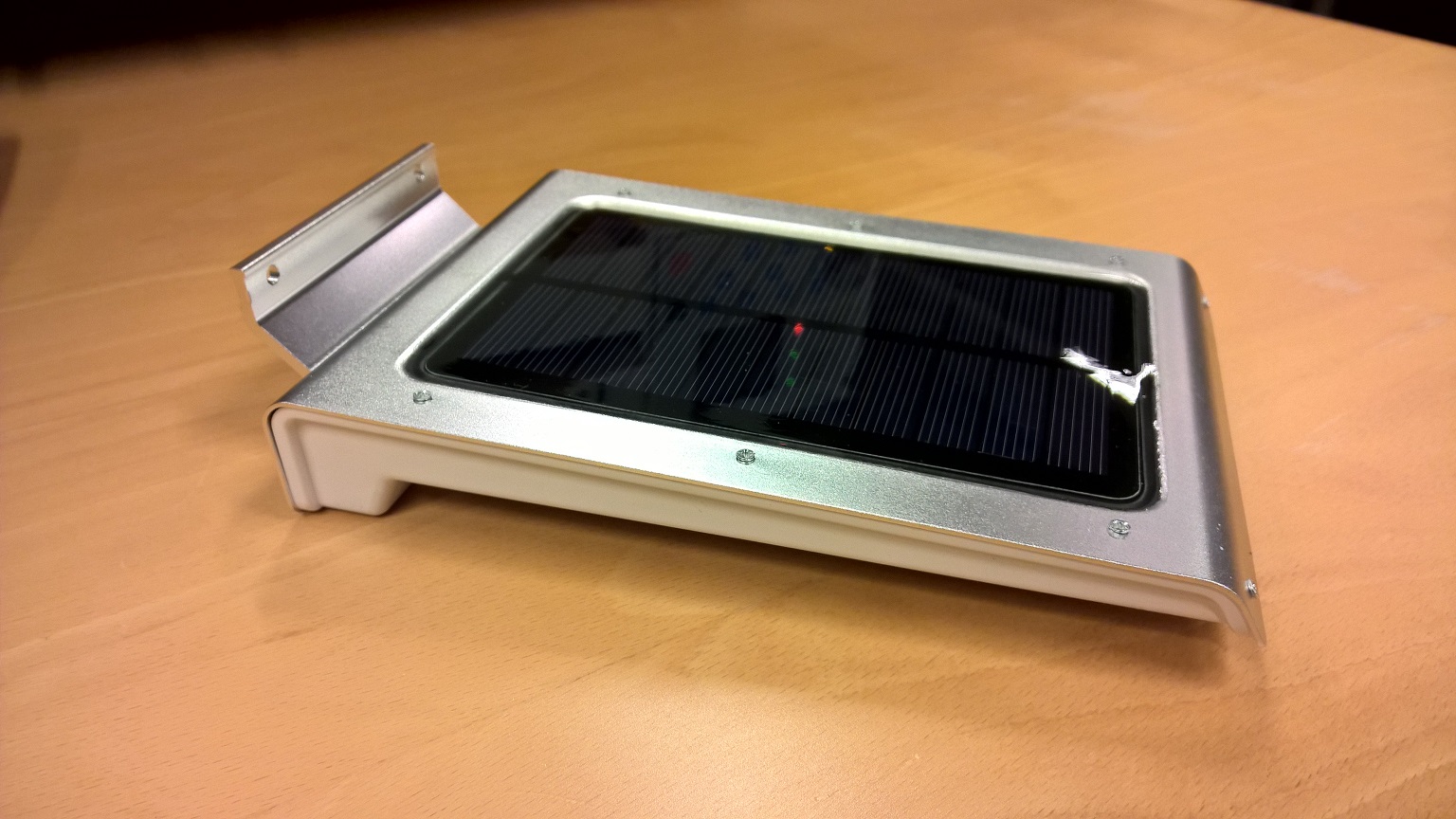
Chinese Solar Lipo powered PIR led lamp.
-
Really interested by your investigations, as i stared build some sensor based on this box (ie the Weather station project). But I had trashed the original pcb and replaced by mine, rebuilding a charger, and getting rid of the builtin PIR. But if it is enough hackable, why not keep it as an addionnal sensor.
So please post your results here.
A few remarks :
-
if there is no LDR, I guess they've simply used the solar panel to detect if there is sun :-)
There should be something like :
Solar+ --------- Resistor ------------ BIS0001 pin 9, so the challenge would be to find which resitor it is, explode it with a cutter or a drill, and put pin 9 to high (ie 3,3v) to make PIR alway ON. -
to controll the light there should be something like this:
BIS0001 pin 2 --------- Transistor (base) : remove this connection and connect pin2 to an arduino input and the transistor base to an arduino output. -
You would also have to check is the retrigering time fit your need, and it the sensibility is well setup...
-
for the arduino software it will really simple, ie some pseudo code :
- When input pin is high send Mysensor Message to gateway
- On incoming Mysensor Message1, set output PIN to High for 30 seconds.
- On incoming Mysensor Message2, set output PIN to blink for 1 hour.
-
-
Really interested by your investigations, as i stared build some sensor based on this box (ie the Weather station project). But I had trashed the original pcb and replaced by mine, rebuilding a charger, and getting rid of the builtin PIR. But if it is enough hackable, why not keep it as an addionnal sensor.
So please post your results here.
A few remarks :
-
if there is no LDR, I guess they've simply used the solar panel to detect if there is sun :-)
There should be something like :
Solar+ --------- Resistor ------------ BIS0001 pin 9, so the challenge would be to find which resitor it is, explode it with a cutter or a drill, and put pin 9 to high (ie 3,3v) to make PIR alway ON. -
to controll the light there should be something like this:
BIS0001 pin 2 --------- Transistor (base) : remove this connection and connect pin2 to an arduino input and the transistor base to an arduino output. -
You would also have to check is the retrigering time fit your need, and it the sensibility is well setup...
-
for the arduino software it will really simple, ie some pseudo code :
- When input pin is high send Mysensor Message to gateway
- On incoming Mysensor Message1, set output PIN to High for 30 seconds.
- On incoming Mysensor Message2, set output PIN to blink for 1 hour.
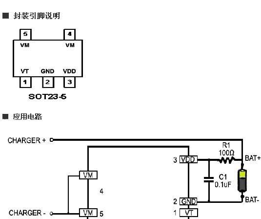
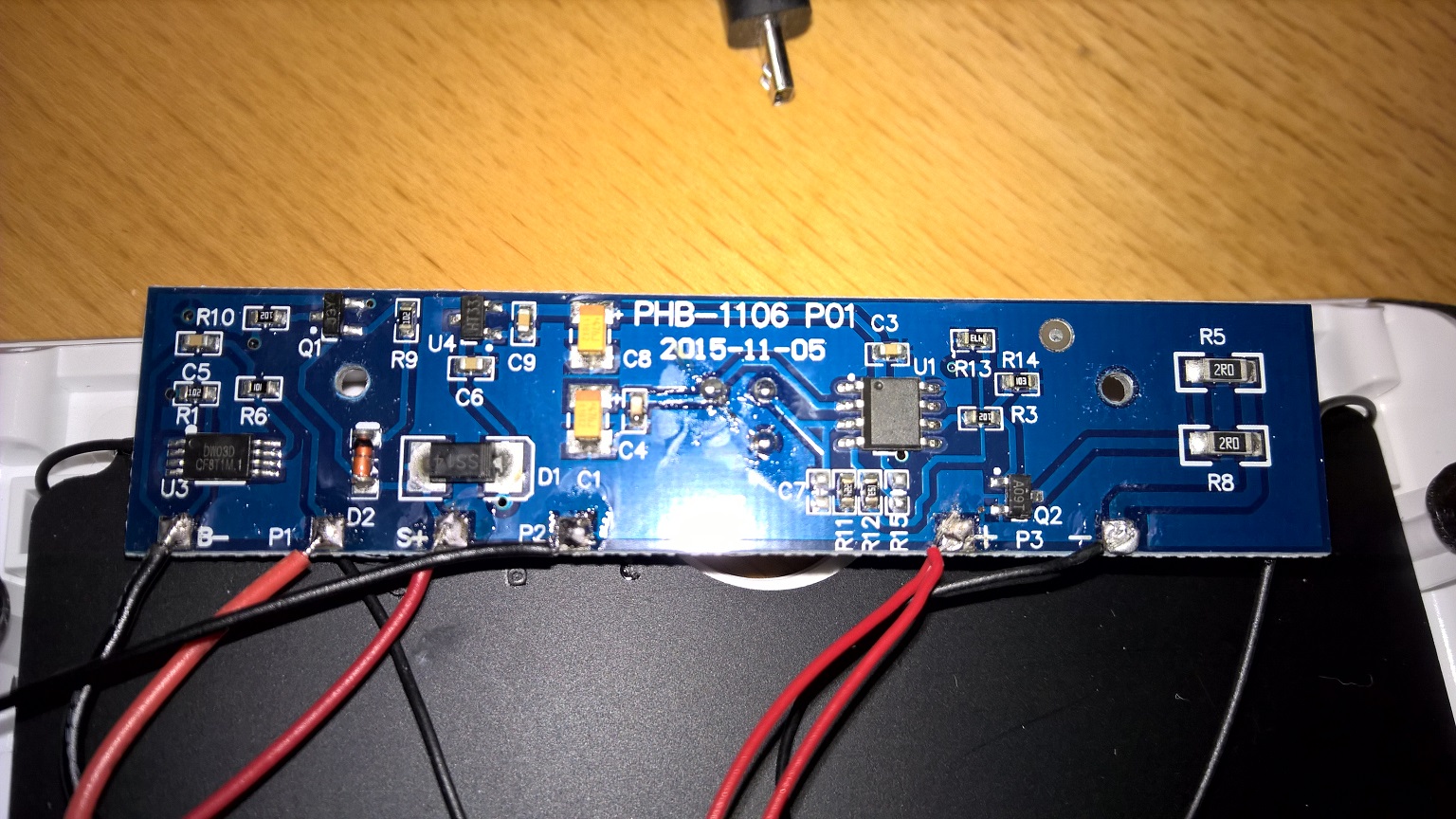
@soif your are partially right, day/night sensor is solar cell
-when solar cell is powering the battery over ic (XB5358A - see picture below), then the LEDs are disconnected (something disconnects load - LED lights),
but
additional findings:
voltage regulator (6206A) is powered from battery all the time (day and night):- which is great that the atmega328 will have full time 3.0V power source.
for BISS0001:
-
pin 9 is always high (3V) - day and night (my solar cell is 5V power supply ON-day, OFF-night)
-
so PIR is powered all the time and when triggered its source signal is ON for around ~25s
-
when PIR is triggered (0,6V), on pin 2 is output ~2.4V for the trigger interval time (25s)
-
so i will try to break pin 2 connection to arduino input, and then connect (transistor base) to an arduino output.
what i still don't know is what drives LEDs:
- at day (solar cell power is high -5V), LEDs are off.
- at night (solar cell power is low- 0V): LEDs work at 2 phases
- when PIR is not active - LEDs ared dimmed (illuminate with little intensity)
- when PIR is active (motion detected)LEDs are verry bright for the time of the trigger interwal (25s)
Questions are:
-
what disconnects (control) the load (LEDs) when battery is being charged from solar cell?
-
is it safe to connect atmega328 to regulator (6206A), i guess it is comparable to BISS0001 & PIR power requirements
so additional very small load (like @GertSanders - minimal 2 switch node ) should not be a problem -
what controlls the trigger interval (it could be shorter than 25s), because after connected arduino the
output pin will configure the LED HIGH intensity interval?
-
-
@soif your are partially right, day/night sensor is solar cell
-when solar cell is powering the battery over ic (XB5358A - see picture below), then the LEDs are disconnected (something disconnects load - LED lights),
but
additional findings:
voltage regulator (6206A) is powered from battery all the time (day and night):- which is great that the atmega328 will have full time 3.0V power source.
for BISS0001:
-
pin 9 is always high (3V) - day and night (my solar cell is 5V power supply ON-day, OFF-night)
-
so PIR is powered all the time and when triggered its source signal is ON for around ~25s
-
when PIR is triggered (0,6V), on pin 2 is output ~2.4V for the trigger interval time (25s)
-
so i will try to break pin 2 connection to arduino input, and then connect (transistor base) to an arduino output.
what i still don't know is what drives LEDs:
- at day (solar cell power is high -5V), LEDs are off.
- at night (solar cell power is low- 0V): LEDs work at 2 phases
- when PIR is not active - LEDs ared dimmed (illuminate with little intensity)
- when PIR is active (motion detected)LEDs are verry bright for the time of the trigger interwal (25s)
Questions are:
-
what disconnects (control) the load (LEDs) when battery is being charged from solar cell?
-
is it safe to connect atmega328 to regulator (6206A), i guess it is comparable to BISS0001 & PIR power requirements
so additional very small load (like @GertSanders - minimal 2 switch node ) should not be a problem -
what controlls the trigger interval (it could be shorter than 25s), because after connected arduino the
output pin will configure the LED HIGH intensity interval?
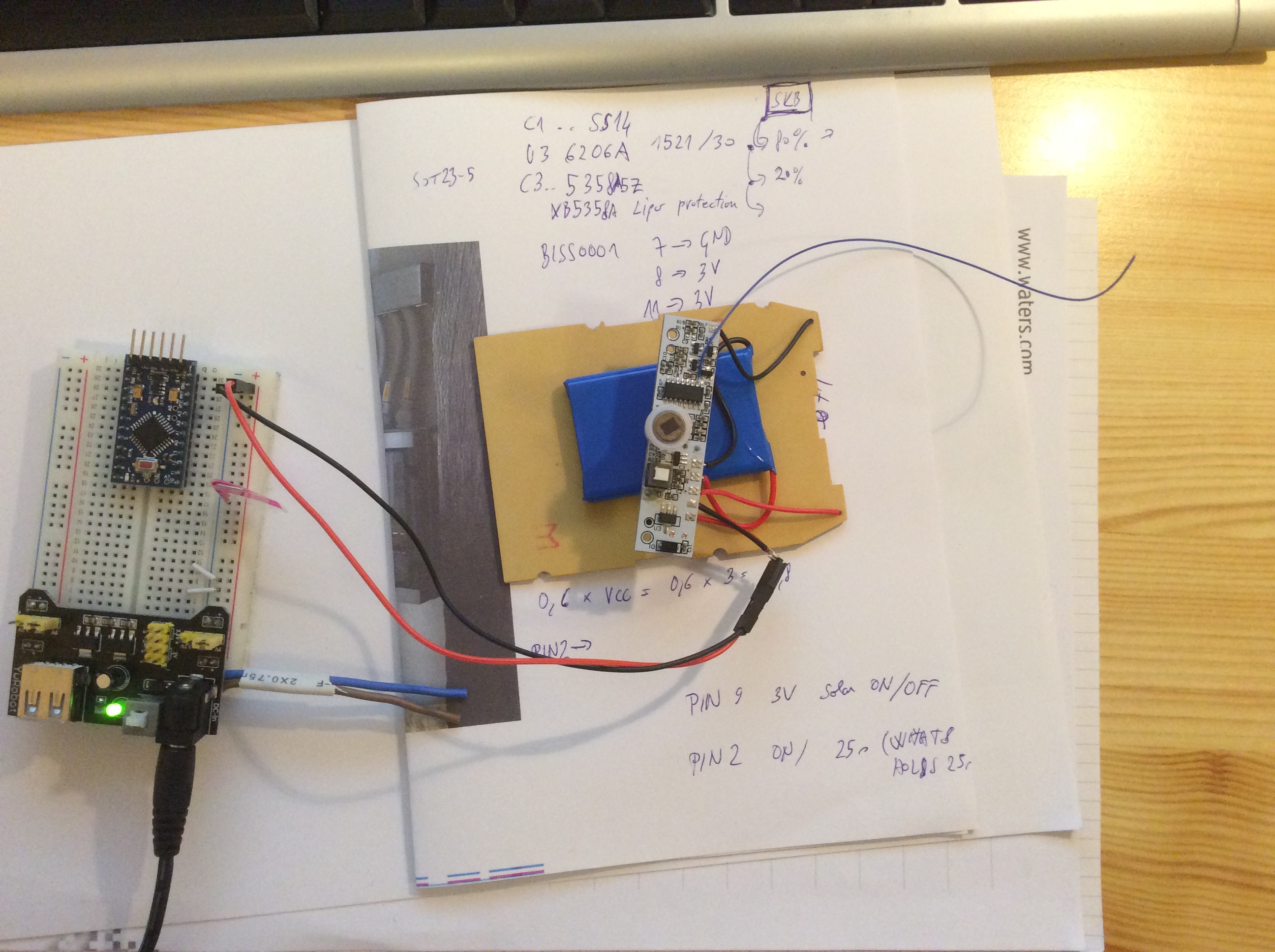
I think "mysensors" aware chinese LED solar lamp could work with a little effort, prototype is working now ( thanks to the forum members for help)
What needs to be done:-
disconnect BISS0001 pin 2 from circuit (i have cut circuit wire on the back of PCB)
-
connect BISS0001 pin 2 to input pin 3 of arduino pro mini (3,3 V model)
-
connect resistor R9 (smd 102 - 1kohm) to output pin 4 of arduino which drives the transistor(Y1) base
-
i think that the easiest way would be to remove resister R9 from circuit. Then connect left part of resistor to input pin of arduino,
-
then wire to arduino output (pin 4) resistor 1K and then connect to right part of removed transistor.
Now i can use the solar light as motion detection and control LED lights independantly.
- motion detection works all day,
Received PUBLISH (d0, q0, r0, m0, 'mygateway1-out/11/12/1/0/16', ... (1 bytes))
0
Received PUBLISH (d0, q0, r0, m0, 'mygateway1-out/11/12/1/0/16', ... (1 bytes))
1
but i can control the lights
root@kali:~# mosquitto_pub -d -h 192.168.1.115 -t "mygateway1-in/11/1/1/0/2" -m "1"
Received CONNACK
Sending PUBLISH (d0, q0, r0, m1, 'mygateway1-in/11/1/1/0/2', ... (1 bytes))
root@kali:~# mosquitto_pub -d -h 192.168.1.115 -t "mygateway1-in/11/1/1/0/2" -m "0"
only when they are not charging (someone would need to figure out how to connect/disconnect
the solar charging - circuit now automatically disconnects the LEDs when there is voltage on solar cell and the battery is charging)usage example:
-
with many solar lights on the garden if motion is detected on one we can light on all of them,
-
they can all blink as an alarm, (i would need help with code)
-
when we need light we can turn lights on from mobile app
-
or any other usage (control something that can be controlled with the power of lipo battery )
-
I think it would be good idea to meassure battery voltage, what divider should i use to meassure Lipo battery voltage, when arduino is powered from 3.0V battery (solar lamp onboard regulator is 3.0V), that we dont drain battery to much
i have combined motion detection and relay scetch:
the code is below (its not optimized, but it works):// Enable debug prints #define MY_DEBUG #define MY_NODE_ID 11 // Enable and select radio type attached #define MY_RADIO_NRF24 //#define MY_RADIO_RFM69 #include <SPI.h> #include <MySensor.h> unsigned long SLEEP_TIME = 120000; // Sleep time between reports (in milliseconds) #define DIGITAL_INPUT_SENSOR 3 // The digital input you attached your motion sensor. (Only 2 and 3 generates interrupt!) #define INTERRUPT DIGITAL_INPUT_SENSOR-2 // Usually the interrupt = pin -2 (on uno/nano anyway) #define CHILD_ID 12 // Id of the sensor child boolean lastMotion = false; // Initialize motion message MyMessage msg(CHILD_ID, V_TRIPPED); #define RELAY_1 4 // Arduino Digital I/O pin number for first relay (second on pin+1 etc) #define NUMBER_OF_RELAYS 1 // Total number of attached relays #define RELAY_ON 1 // GPIO value to write to turn on attached relay #define RELAY_OFF 0 // GPIO value to write to turn off attached relay void setup() { pinMode(DIGITAL_INPUT_SENSOR, INPUT); // sets the motion sensor digital pin as input for (int sensor=1, pin=RELAY_1; sensor<=NUMBER_OF_RELAYS;sensor++, pin++) { // Then set relay pins in output mode pinMode(pin, OUTPUT); // Set relay to last known state (using eeprom storage) digitalWrite(pin, loadState(sensor)?RELAY_ON:RELAY_OFF); } } void presentation() { // Send the sketch version information to the gateway and Controller sendSketchInfo("Motion Sensor and pir", "1.0"); // Register all sensors to gw (they will be created as child devices) present(CHILD_ID, S_MOTION); for (int sensor=1, pin=RELAY_1; sensor<=NUMBER_OF_RELAYS;sensor++, pin++) { // Register all sensors to gw (they will be created as child devices) present(sensor, S_LIGHT); } } void loop() { // Read digital motion value boolean tripped = digitalRead(DIGITAL_INPUT_SENSOR) == HIGH; if (lastMotion != tripped) { Serial.println(tripped); lastMotion = tripped; send(msg.set(tripped?"1":"0")); // Send tripped value to gw } // Sleep until interrupt comes in on motion sensor. Send update every two minute. //sleep(INTERRUPT,CHANGE, SLEEP_TIME); } void receive(const MyMessage &message) { // We only expect one type of message from controller. But we better check anyway. if (message.type==V_LIGHT) { // Change relay state digitalWrite(message.sensor-1+RELAY_1, message.getBool()?RELAY_ON:RELAY_OFF); // Store state in eeprom saveState(message.sensor, message.getBool()); // Write some debug info Serial.print("Incoming change for sensor:"); Serial.print(message.sensor); Serial.print(", New status: "); Serial.println(message.getBool()); } }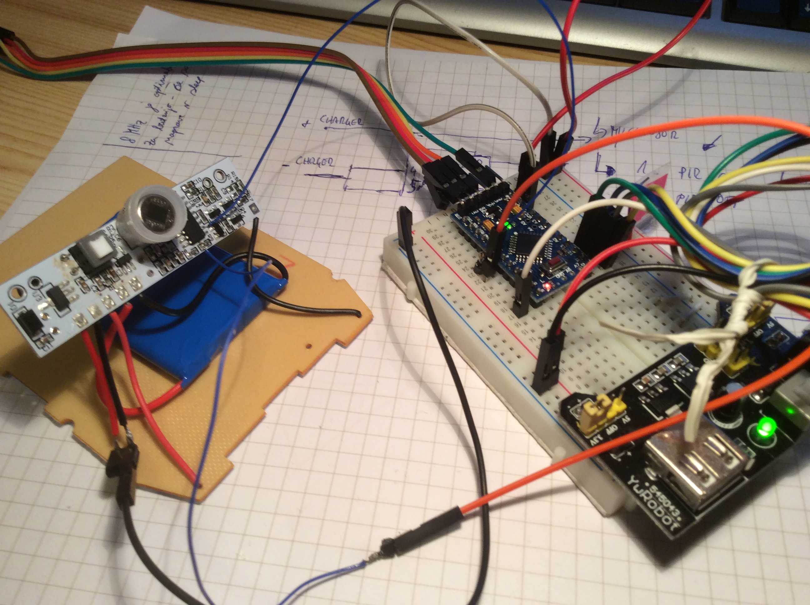
-
very nice to see that good progress was made :-)
-
@gyro
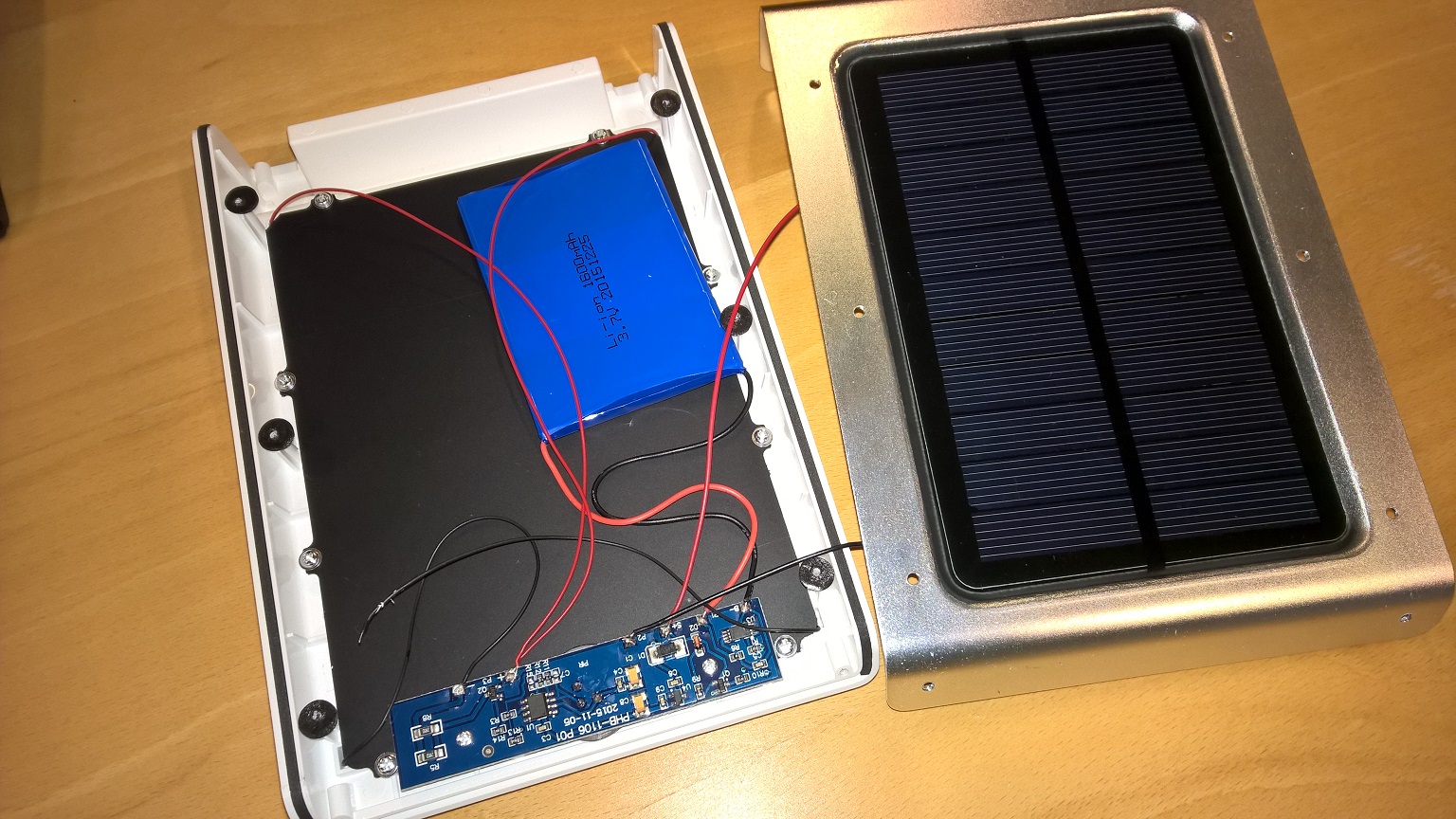
Keep up the good work debugging this chinese box !This box is a really good value for money box to build mysensors projects ( at least box + lipo + solar panel).
If your investigations let us to also use the built in Charger / PIR / LEDS , it would just be amazing.
Please keep us in touch ! ;-)
-
@gyro
Keep up the good work debugging this chinese box !This box is a really good value for money box to build mysensors projects ( at least box + lipo + solar panel).
If your investigations let us to also use the built in Charger / PIR / LEDS , it would just be amazing.
Please keep us in touch ! ;-)
@soif , @GertSanders
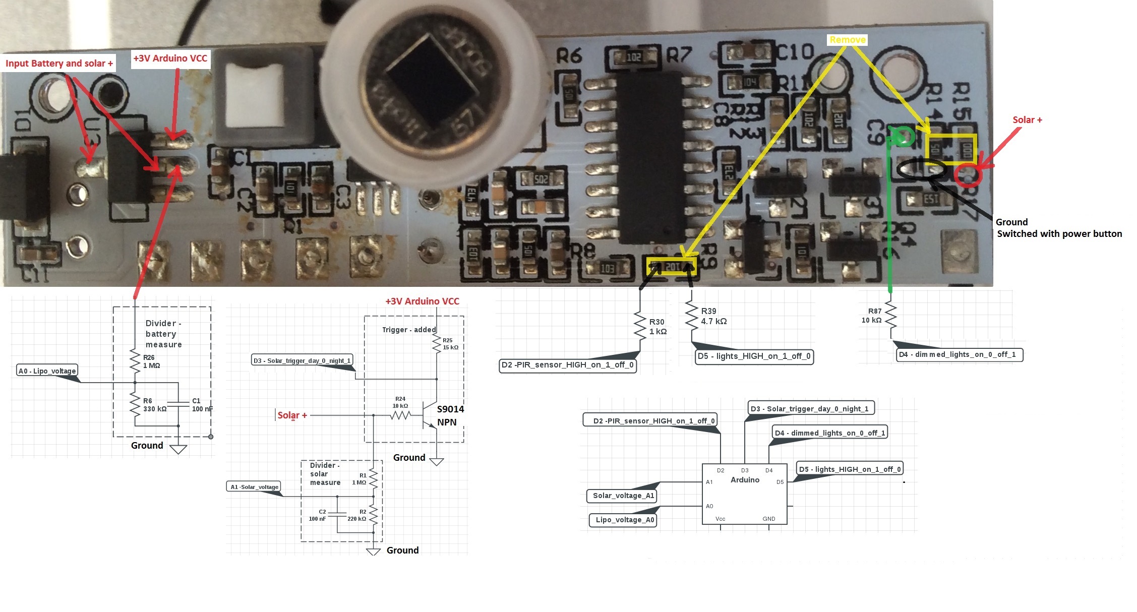
some progress was made, but i need an hardware advice.This is the part of schematic that drives the LEDs.
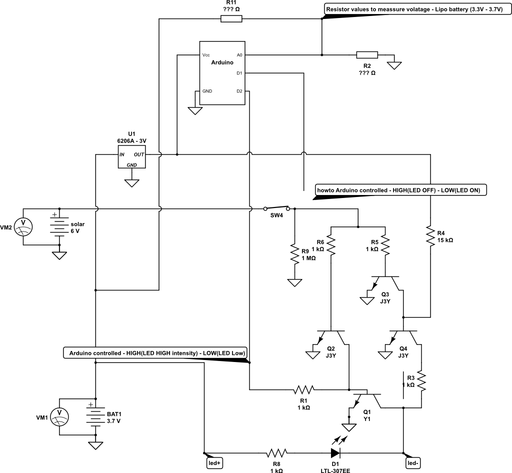
First the battery is not connected directly (as here in schematic) but over protection IC logic.
Question 1:
Current circuit works as follows:
- When solar cell voltage is higher than 0.7V , LED is OFF (sort off day/night sensor).
- When solar voltage is lower than 0,7V, LED is shining with low intensity
What is the the correct way to connect arduino pin D1 to take control over above described default behavior? (disconnect the line at SW4 and remove R9 -1Mohm)?
Question 2:
Which voltage measurement technique (internal reference or reference to regulated Vcc voltage) should i use to meassure Lipo voltage?
What are correct/recommended resistor value for optimal battery utilization.
Should this reference be used: https://github.com/rlogiacco/BatterySenseWould make sense to measure also solar cell voltage?
Question 3:
Is arduino pin D2 connect properly? It control two level LED intensity:
pin HIGH - LED glows with HIGH intensity (between led+ and led- is ~4V) pin LOW LED glows with LOW intensity (between led+ and led- is ~2,5V)Thanks for help and recommendations
I have asked the same here, but no perfect answer jet:
http://electronics.stackexchange.com/questions/218114/solar-battery-powered-leds-circuit-arduino-controlled -
Since you are using a atmega328p, it does make sense to measure the battery level and solar power level.
If you make a node which does NOT sleep all the time, then monitoring both voltage levels is the starting point to make decisions.
I'm guessing you want to add a node using the battery, so a node that sleeps until something needs to be done.
In that case we need a trigger when the light is bright enough to switch off the leds, and dark enough to switch them on again.The trigger to wake up from sleep should be a voltage change on pin D2 or D3, and the voltage difference needs to be from below the lowest "HIGH" threshold to above the highest "LOW" threshold. Check the specification for the atmega328 you use, as this depends on the working voltage of the processor.
The question I ask myself is what is the lowest voltage you get from the solar cell ? Looking at the circuit, they use the voltage of the solar cell to open the gate of a transistor, which then pulls the emitter voltage of a transistor to ground, which in turn switches off a second transistor with is feeding the battery current to the LEDs.
Your question of the values of R2 and R11 is actually how to measure voltages over a resistor divider? You can choose any value of resistors, but their ratio is what is important.
To calculate the resistor values:
To measure at a maximum of 5V on an analog pin:
R11 = R2 * (1 - voltage-ratio) / voltage-ratio
To go from 6V to 5V the ratio = 5V / 6V = 0.83
Take R2 as 1M Ohm, then R11 = 1M * (1 - 0.83) / 0.83 = 205K => a common value is 220K
To check: voltage over R2 (which is the input voltage on the analog pin A0)
V(A0) = Vinput * R2 / (R1 + R2) = 6V * 1M / (1M+220K) = 4.9 V
-
Since you are using a atmega328p, it does make sense to measure the battery level and solar power level.
If you make a node which does NOT sleep all the time, then monitoring both voltage levels is the starting point to make decisions.
I'm guessing you want to add a node using the battery, so a node that sleeps until something needs to be done.
In that case we need a trigger when the light is bright enough to switch off the leds, and dark enough to switch them on again.The trigger to wake up from sleep should be a voltage change on pin D2 or D3, and the voltage difference needs to be from below the lowest "HIGH" threshold to above the highest "LOW" threshold. Check the specification for the atmega328 you use, as this depends on the working voltage of the processor.
The question I ask myself is what is the lowest voltage you get from the solar cell ? Looking at the circuit, they use the voltage of the solar cell to open the gate of a transistor, which then pulls the emitter voltage of a transistor to ground, which in turn switches off a second transistor with is feeding the battery current to the LEDs.
Your question of the values of R2 and R11 is actually how to measure voltages over a resistor divider? You can choose any value of resistors, but their ratio is what is important.
To calculate the resistor values:
To measure at a maximum of 5V on an analog pin:
R11 = R2 * (1 - voltage-ratio) / voltage-ratio
To go from 6V to 5V the ratio = 5V / 6V = 0.83
Take R2 as 1M Ohm, then R11 = 1M * (1 - 0.83) / 0.83 = 205K => a common value is 220K
To check: voltage over R2 (which is the input voltage on the analog pin A0)
V(A0) = Vinput * R2 / (R1 + R2) = 6V * 1M / (1M+220K) = 4.9 V
@GertSanders I think i managed to successfully connect arduino with solar lamp.
My prototype is working, and has the following functions:
- Measure battery voltage (when charging it is alway 100% - makes sense)
- Measure solar voltage (can be omitted - but resistor should be there for a transistor to work properly)
- Solar power day/night trigger with transistor as a switch (can be used wake up arduino from sleep)
- PIR sensor (can be used wake up arduino from sleep)
- Lights on/off dimmed brightness
- Lights on/off high brightness ( original resistor R9 -1k was replaced with 4.7k - i think it draws to much current and sometimes hangs arduino)
I will post the code later, but every part works with default "mysensor" examples
How to connect and how to add elements see picture:
-
@GertSanders I think i managed to successfully connect arduino with solar lamp.
My prototype is working, and has the following functions:
- Measure battery voltage (when charging it is alway 100% - makes sense)
- Measure solar voltage (can be omitted - but resistor should be there for a transistor to work properly)
- Solar power day/night trigger with transistor as a switch (can be used wake up arduino from sleep)
- PIR sensor (can be used wake up arduino from sleep)
- Lights on/off dimmed brightness
- Lights on/off high brightness ( original resistor R9 -1k was replaced with 4.7k - i think it draws to much current and sometimes hangs arduino)
I will post the code later, but every part works with default "mysensor" examples
How to connect and how to add elements see picture:
@gyro
Very nice work !!!! -
higher math for me...
Great...Can you use the motion seperate from the liight?
And can u use the light with a switch option? [ i will turn on the light when there is motion.. ]
Or is the light switching only on lux?Domoticz, with a lot of working hardware, include mysensors :-)
OpenPLI, RuneAudio, Solarmeter, etc......Not a great builder of software and hardware, more a user...
Only i try to do my best :-( -
higher math for me...
Great...Can you use the motion seperate from the liight?
And can u use the light with a switch option? [ i will turn on the light when there is motion.. ]
Or is the light switching only on lux?@GertSanders thanks, you have motivated my research
@Dylano the purpose of this project was exactly what you have asked.
The lamp is now mysensors aware.
Every task can be operated separately.-
When there is dark, the trigger is send, when the sun shines, the trigger is send. (transistor as switch). In scetch i use it as magnet switch part of code. When trigger is received (can wake up arduino), than you decide with controller what you want to do .
-
PIR acts as classic PIR sensor and can also be used as trigger. (can wake up arduino), than you decide with controller what you want to do.
-
The Lamp have two phases and can be controlled with controller (i control it over mqtt for now)
-
phase one is dimmed light (relay 1)
-
phase two is high bright light (relay 2)
Below is code that works for now. I wil improve it in next few days
// Enable debug prints #define MY_DEBUG #define MY_NODE_ID 11 // Enable and select radio type attached #define MY_RADIO_NRF24 //#define MY_RADIO_RFM69 #include <SPI.h> #include <MySensor.h> #include <Bounce2.h> //unsigned long SLEEP_TIME = 120000; // Sleep time between reports (in milliseconds) #define DIGITAL_INPUT_SENSOR 2 // The digital input you attached your motion sensor. (Only 2 and 3 generates interrupt!) //#define INTERRUPT DIGITAL_INPUT_SENSOR-2 // Usually the interrupt = pin -2 (on uno/nano anyway) #define CHILD_ID 12 // Id of the sensor child boolean lastMotion = false; // Initialize motion message - start MyMessage msg(CHILD_ID, V_TRIPPED); //trigger solar power day on/off -start #define CHILD_ID_SW 5 #define BUTTON_PIN 5 // Arduino Digital I/O pin for button/reed switch Bounce debouncer = Bounce(); int oldValue = -1; // Change to V_LIGHT if you use S_LIGHT in presentation below MyMessage SolarMsg(CHILD_ID_SW, V_TRIPPED); // trigger solar - end #define RELAY_1 3 // Arduino Digital I/O pin number for first relay (second on pin+1 etc) #define NUMBER_OF_RELAYS 2 // Total number of attached relays #define RELAY_ON 1 // GPIO value to write to turn on attached relay #define RELAY_OFF 0 // GPIO value to write to turn off attached relay void setup() { //trigger solar power day on/off - start // Setup the button pinMode(BUTTON_PIN, INPUT); // Activate internal pull-up digitalWrite(BUTTON_PIN, HIGH); // After setting up the button, setup debouncer debouncer.attach(BUTTON_PIN); debouncer.interval(5); //trigger solar - end pinMode(DIGITAL_INPUT_SENSOR, INPUT); // sets the motion sensor digital pin as input for (int sensor = 1, pin = RELAY_1; sensor <= NUMBER_OF_RELAYS; sensor++, pin++) { // Then set relay pins in output mode pinMode(pin, OUTPUT); // Set relay to last known state (using eeprom storage) digitalWrite(pin, loadState(sensor) ? RELAY_ON : RELAY_OFF); } } void presentation() { // Send the sketch version information to the gateway and Controller sendSketchInfo("Motion Sensor and light", "1.0"); // Register all sensors to gw (they will be created as child devices) present(CHILD_ID, S_MOTION); for (int sensor = 1, pin = RELAY_1; sensor <= NUMBER_OF_RELAYS; sensor++, pin++) { // Register all sensors to gw (they will be created as child devices) present(sensor, S_LIGHT); // Register binary input sensor to gw (they will be created as child devices) // You can use S_DOOR, S_MOTION or S_LIGHT here depending on your usage. // If S_LIGHT is used, remember to update variable type you send in. See "msg" above. present(CHILD_ID_SW, S_DOOR); } } void loop() { // Read digital motion value boolean tripped = digitalRead(DIGITAL_INPUT_SENSOR) == HIGH; if (lastMotion != tripped) { Serial.println(tripped); lastMotion = tripped; send(msg.set(tripped ? "1" : "0")); // Send tripped value to gw } // Sleep until interrupt comes in on motion sensor. Send update every two minute. //sleep(INTERRUPT,CHANGE, SLEEP_TIME); //trigger solar power day on/off - start debouncer.update(); // Get the update value int value = debouncer.read(); if (value != oldValue) { // Send in the new value send(SolarMsg.set(value == HIGH ? 1 : 0)); oldValue = value; //trigger solar power day on/off - stop } } void receive(const MyMessage &message) { // We only expect one type of message from controller. But we better check anyway. if (message.type == V_LIGHT) { // Change relay state digitalWrite(message.sensor - 1 + RELAY_1, message.getBool() ? RELAY_ON : RELAY_OFF); // Store state in eeprom saveState(message.sensor, message.getBool()); // Write some debug info Serial.print("Incoming change for sensor:"); Serial.print(message.sensor); Serial.print(", New status: "); Serial.println(message.getBool()); } }``` -
-
mmm i ordered 1...
So i hope i gonna ix this...
It is looking higher mathematicsWill see... when i have time..
Thanks for the sketch!!!
Give it a try in a uno ... -
guess what...
I do have a:
http://www.ebay.com/itm/161885080971?_trksid=p2057872.m2749.l2649&ssPageName=STRK%3AMEBIDX%3AIT
Exact the same board in of this light...
I think i going to try the make this work...Only i do not understand exact the wiring of your example.
Will you please make a list of exact stuff to buy.
And make some more pictures, from the good places..And a thing that i see.
You use D2 from the arduino.
Is that not a one for the radio? -
@GertSanders I think i managed to successfully connect arduino with solar lamp.
My prototype is working, and has the following functions:
- Measure battery voltage (when charging it is alway 100% - makes sense)
- Measure solar voltage (can be omitted - but resistor should be there for a transistor to work properly)
- Solar power day/night trigger with transistor as a switch (can be used wake up arduino from sleep)
- PIR sensor (can be used wake up arduino from sleep)
- Lights on/off dimmed brightness
- Lights on/off high brightness ( original resistor R9 -1k was replaced with 4.7k - i think it draws to much current and sometimes hangs arduino)
I will post the code later, but every part works with default "mysensor" examples
How to connect and how to add elements see picture:
-
mmm i ordered 1...
So i hope i gonna ix this...
It is looking higher mathematicsWill see... when i have time..
Thanks for the sketch!!!
Give it a try in a uno ...@Dylano Great to hear that the light has the same board...please post a picture.
My light is still protoype connected together on protoboard - connected to arduino pro mini - i can post only a picture connected elements on protoboard for now.
I am trying to put all together in openhab now.
I will try to make a list of exact elements.
I have free D2 pin on arduino pro mini. -
Got myself a similar PIR LED lamp. The functionality seems like it is the same but the circuit board is different.
@korttoma
Nice to see some interest in smart solar lamps :)
It looks like an updated version (at least i like it more from your pictures). Could you post an order link.
I think this one should be even easier to intercept with "mysensors", beacause i see only two transistors and circuit connectios are clearly visible.so lets try to understand the circuit:
-U3 is probably battery protection circuit- Q1 i think is voltage regulator HT33 - to power arduino wih 3.3V (meassure voltage)
- take a photo of PIR sensor from front side (is there any ic elements)?
- U1 - i would guess PIR sensor IC logic - leg 6 (count from dot on IC) should be output (meassure voltage - high 3,3 V when motion detected):
-if it is output from PIR just remove R3 and IC ouput goes over resistor to you arduino input. - the output goes over resistor to Q2
-whats is left - you have to figure out what drives resistor Q1(J3y) : - i gues its driven by solar cell, than collector is connected to resistor R10, resesitor is than connected over board to the other side.......
Hello! It looks like you're interested in this conversation, but you don't have an account yet.
Getting fed up of having to scroll through the same posts each visit? When you register for an account, you'll always come back to exactly where you were before, and choose to be notified of new replies (either via email, or push notification). You'll also be able to save bookmarks and upvote posts to show your appreciation to other community members.
With your input, this post could be even better 💗
Register Login