NRF24L01+ range of only few meters
-
Typically you point it up. It gives you vertical polarization.
You point both transmitter and received wire antennas same directions.
It's possible that your chips are at fault, if non of other tricks worked (capacitors, clear power, enough current, short wires, lo-noise rf spectrum channel) try other transceivers.@Igor-Katkov said:
It's possible that your chips are at fault, if non of other tricks worked (capacitors, clear power, enough current, short wires, lo-noise rf spectrum channel) try other transceivers.
I've tried the cling wrap and tin foil trick - this seems to have worked. Was getting 5m or so, now I"m getting constant readings from one side of the house to the other (through multiple walls!). 20m
Update: Just as I posted this the sensor stopped working :(
I'm really having major reliability issues with these sensors and am thinking of scrapping them altogether now. Its a pity these are such a hit and miss affair.
-
@Igor-Katkov said:
It's possible that your chips are at fault, if non of other tricks worked (capacitors, clear power, enough current, short wires, lo-noise rf spectrum channel) try other transceivers.
I've tried the cling wrap and tin foil trick - this seems to have worked. Was getting 5m or so, now I"m getting constant readings from one side of the house to the other (through multiple walls!). 20m
Update: Just as I posted this the sensor stopped working :(
I'm really having major reliability issues with these sensors and am thinking of scrapping them altogether now. Its a pity these are such a hit and miss affair.
My guess is if the sensors work and suddenly stop, you have something else interfering with the radios. Could be a microwave, AC unit, etc.
I about gave up on this project last year. I had several units built that worked fine and then one day all of them quit. After several frustrating weeks, I discovered my wifi router somehow was interfering with the units. It was an old unit and I needed to replace it. After it was gone, everything went back to working correctly.
-
@gmccarthy don't give up. You seem to be on the right track and already got great results. :+1:
Maybe go bare bones and try the rf24 scanner,
https://maniacbug.github.io/RF24/scanner_8pde-example.html
to find the best nrf24 channel for your. :) -
@gmccarthy don't give up. You seem to be on the right track and already got great results. :+1:
Maybe go bare bones and try the rf24 scanner,
https://maniacbug.github.io/RF24/scanner_8pde-example.html
to find the best nrf24 channel for your. :) -
@Oitzu said:
@gmccarthy don't give up. You seem to be on the right track and already got great results.
Maybe go bare bones and try the rf24 scannerThanks. This looks interesting. Will give it a shot.
@gmccarthy As far as I know, NRF channels above 100 should not have interference from Wifi 2.4 Ghz. I was getting 2-3 meters at best. I changed the channel to 110 and corrected the power supply a little. I am yet to implement cling wrap.
I get 10-15 meters between two standard modules inside an apartment. The apartment is like a faraday cage and sometimes I cannot get wifi on the outer extremes while router is in the middle. I am getting sensor readings from one end to the other now, passing through the area where I have the router. So, I think interference is critical in distance.
-
Hey guys I seem to have similar (but even worse) problems here. I am building a rgbwController and have huge problems connecting that to my gateway although it's only ~3m and no obstacle away.
I am using 4,7uF caps on both sides. Stepdown from 12V + another cap on the rgbwController's side and the arduino uno's 3.3V on the other side. I also tried another external 3.3V power source here (but that did not help either).
I tried changing the channel to 111 but that seems to have made it even worse.Any ideas how to debug that or what to change?
It's really sad to have the setup up and running and then being unable to really use it due to radio problems ;( -
@LastSamurai Which nrf24l01+ modules are you using on which side?
Whats the typical error pattern you get? (Failed transmission from gw to node or from node to gw?)
Need to know your exact construction, before guessing what could be wrong. -
@LastSamurai Which nrf24l01+ modules are you using on which side?
Whats the typical error pattern you get? (Failed transmission from gw to node or from node to gw?)
Need to know your exact construction, before guessing what could be wrong.@Oitzu
I am using the "standard" ones on both sides ("sodial" ones. I think these). My logs from the controller from my thread look like this:0;0;3;0;9;send: 0-0-123-123 s=1,c=1,t=2,pt=0,l=1,sg=0,st=fail:1 0;0;3;0;9;read: 123-123-0 s=1,c=1,t=2,pt=0,l=1,sg=0:1 123;1;1;1;2;1 0;0;3;0;9;send: 0-0-123-123 s=1,c=1,t=2,pt=0,l=1,sg=0,st=fail:1 0;0;3;0;9;send: 0-0-123-123 s=1,c=1,t=2,pt=0,l=1,sg=0,st=fail:0 0;0;3;0;9;send: 0-0-123-123 s=1,c=1,t=2,pt=0,l=1,sg=0,st=fail:1 0;0;3;0;9;send: 0-0-123-123 s=1,c=1,t=2,pt=0,l=1,sg=0,st=fail:1 0;0;3;0;9;send: 0-0-123-123 s=1,c=1,t=2,pt=0,l=1,sg=0,st=fail:0 0;0;3;0;9;send: 0-0-123-123 s=1,c=1,t=2,pt=0,l=1,sg=0,st=ok:1 0;0;3;0;9;send: 0-0-123-123 s=1,c=1,t=2,pt=0,l=1,sg=0,st=fail:0 0;0;3;0;9;read: 123-123-0 s=1,c=1,t=2,pt=0,l=1,sg=0:0 123;1;1;1;2;0 0;0;3;0;9;send: 0-0-123-123 s=1,c=1,t=2,pt=0,l=1,sg=0,st=fail:1 0;0;3;0;9;send: 0-0-123-123 s=1,c=1,t=2,pt=0,l=1,sg=0,st=ok:0 0;0;3;0;9;read: 123-123-0 s=1,c=1,t=2,pt=0,l=1,sg=0:0 123;1;1;1;2;0 0;0;3;0;9;send: 0-0-123-123 s=1,c=1,t=2,pt=0,l=1,sg=0,st=ok:1 0;0;3;0;9;read: 123-123-0 s=1,c=1,t=2,pt=0,l=1,sg=0:1 123;1;1;1;2;1 0;0;3;0;9;send: 0-0-123-123 s=1,c=1,t=2,pt=0,l=1,sg=0,st=fail:0 0;0;3;0;9;read: 123-123-0 s=1,c=1,t=2,pt=0,l=1,sg=0:0 123;1;1;1;2;0 0;0;3;0;9;send: 0-0-123-123 s=1,c=1,t=2,pt=0,l=1,sg=0,st=fail:1 0;0;3;0;9;send: 0-0-123-123 s=1,c=1,t=2,pt=0,l=1,sg=0,st=fail:0 0;0;3;0;9;send: 0-0-123-123 s=1,c=1,t=2,pt=0,l=1,sg=0,st=fail:1 0;0;3;0;9;send: 0-0-123-123 s=1,c=1,t=2,pt=0,l=1,sg=0,st=fail:0 0;0;3;0;9;send: 0-0-123-123 s=1,c=1,t=2,pt=0,l=1,sg=0,st=fail:1 0;0;3;0;9;send: 0-0-123-123 s=1,c=1,t=2,pt=0,l=1,sg=0,st=fail:0 0;0;3;0;9;send: 0-0-123-123 s=1,c=1,t=2,pt=0,l=1,sg=0,st=fail:1 0;0;3;0;9;send: 0-0-123-123 s=1,c=1,t=2,pt=0,l=1,sg=0,st=fail:0 0;0;3;0;9;read: 123-123-0 s=1,c=1,t=2,pt=0,l=1,sg=0:0 123;1;1;1;2;0 0;0;3;0;9;send: 0-0-123-123 s=1,c=1,t=2,pt=0,l=1,sg=0,st=fail:1 0;0;3;0;9;send: 0-0-123-123 s=1,c=1,t=2,pt=0,l=1,sg=0,st=ok:0 0;0;3;0;9;read: 123-123-0 s=1,c=1,t=2,pt=0,l=1,sg=0:0 123;1;1;1;2;0 0;0;3;0;9;send: 0-0-123-123 s=1,c=1,t=2,pt=0,l=1,sg=0,st=fail:1 0;0;3;0;9;read: 123-123-0 s=1,c=1,t=2,pt=0,l=1,sg=0:1 123;1;1;1;2;1 0;0;3;0;9;send: 0-0-123-123 s=1,c=1,t=2,pt=0,l=1,sg=0,st=fail:1 0;0;3;0;9;send: 0-0-123-123 s=1,c=1,t=41,pt=0,l=9,sg=0,st=fail:#00000 0;0;3;0;9;read: 123-123-0 s=1,c=1,t=41,pt=0,l=9,sg=0:#000000FF 123;1;1;1;41;#000000FF 0;0;3;0;9;send: 0-0-123-123 s=1,c=1,t=3,pt=0,l=3,sg=0,st=fail:100 0;0;3;0;9;send: 0-0-123-123 s=1,c=1,t=2,pt=0,l=1,sg=0,st=fail:0 0;0;3;0;9;read: 123-123-0 s=1,c=1,t=2,pt=0,l=1,sg=0:0 123;1;1;1;2;0 0;0;3;0;9;send: 0-0-123-123 s=1,c=1,t=2,pt=0,l=1,sg=0,st=fail:1 0;0;3;0;9;read: 123-123-0 s=1,c=1,t=2,pt=0,l=1,sg=0:1 123;1;1;1;2;1Sometimes I get a fail message but the lights are reacting (so I guess the ack didn't reach the gateway). I wasn't able to debug the rgbw controller in its position yet because it's sitting on top of a cupboard.
If you need more infos just tell me.I'll try out another arduino as gateway later.
PS according to this post they might be "fake" though ;) Although others seemed to have used them for mysensors too (comments)
-
Something seems to be off with the controller. I tried the same code on another arduino uno and it worked just fine. A little less distance perhaps but no errors at all. I'll try to do some hardware testing and measuring tomorrow.
-
@LastSamurai also keep in mind that if you are using the LM2596 buck converter that you need to use a post ripple filter.
I explained that here: http://blog.blackoise.de/2016/03/building-a-lc-filter-for-your-nrf24l01-palna-module/. -
@LastSamurai also keep in mind that if you are using the LM2596 buck converter that you need to use a post ripple filter.
I explained that here: http://blog.blackoise.de/2016/03/building-a-lc-filter-for-your-nrf24l01-palna-module/.@Oitzu Thanks for the hint! That might actually have been a reason why it worked for some time and then stoped, right? I have ordered the components needed and will test it soon.
I don't actually use the LM2596 modules but these smaller ones but I guess they use similar parts.Did you have similar issues?
-
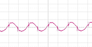
@LastSamurai can't really say for this modules.
The datasheet for the LM2596 says you should use a post ripple filter for low noise, because it generates sawtooth ripple at its switching frequency (150khz). The china-clones of the lm2596 seem to be even worse generating even greater ripple with 50khz.Whats the ic on the mini dc-dc converter called? The ebay offer says it has a output ripple of 30mV bute more then often these values are the best case. Maybe a datasheets is available.
-
It would be so useful to be able to measure the supply voltages with an oscilloscope. So far all my transmission problems have been related to the power supplies. Only after using a scope I fully realized that. No more freezing or poor function of the nodes.
Also, using a brand supply doesn't necessarily mean a clean signal. This (again) is an illustrative post about USB supplies, worth to take a look at:
http://www.righto.com/2012/10/a-dozen-usb-chargers-in-lab-apple-is.html -
It would be so useful to be able to measure the supply voltages with an oscilloscope. So far all my transmission problems have been related to the power supplies. Only after using a scope I fully realized that. No more freezing or poor function of the nodes.
You are totally right! Unfortunately i also don't own a oscilloscope. But a cheaper usb oscilloscope is on my need to have list because of a all the trouble and testing i had with this...
-
It would be so useful to be able to measure the supply voltages with an oscilloscope. So far all my transmission problems have been related to the power supplies. Only after using a scope I fully realized that. No more freezing or poor function of the nodes.
You are totally right! Unfortunately i also don't own a oscilloscope. But a cheaper usb oscilloscope is on my need to have list because of a all the trouble and testing i had with this...
@Oitzu DSO138 scope is like $25 from aliexpress
-
@Igor-Katkov said:
DSO138
Was thinking of something like the Hantek 6022BE. Most EE guys would say "eh... crap", but oh well.. it's just a hobby and i'm not willing to pay hundreds of dollars for it. :D
-
One might think that to measure ripple noise of $2 Chinese power supply ~$70 unit is an overkill :-)
-
@Igor-Katkov eh... now you just sound like my gf. :P
No, you're right. But it may come handy in some other situations. :) -
It would be so useful to be able to measure the supply voltages with an oscilloscope. So far all my transmission problems have been related to the power supplies. Only after using a scope I fully realized that. No more freezing or poor function of the nodes.
Also, using a brand supply doesn't necessarily mean a clean signal. This (again) is an illustrative post about USB supplies, worth to take a look at:
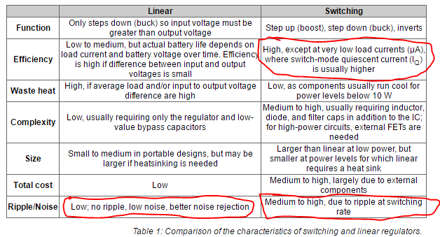
http://www.righto.com/2012/10/a-dozen-usb-chargers-in-lab-apple-is.html@Nuubi My two cents.. I have been measuring (with a scope ;)) quite a lot of power supplies and have come to the conclusion that most (inexpensive) switching power regulators (buck & boost) should be avoided when a clean supply is needed. All (or most) of these just not have enough filtering (LC) for the switching frequency. So go for a 'linear' version (for buck/ step-down), especially for the radio. Also PIR sensors are very sensitive.
Lucky for us most MySensors circuits need very little power, so the efficiency of a linear converter (for buck) is sufficient in most cases.
from digikey
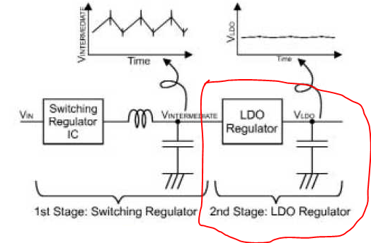
or use a linear converter as "second stage"
Hello! It looks like you're interested in this conversation, but you don't have an account yet.
Getting fed up of having to scroll through the same posts each visit? When you register for an account, you'll always come back to exactly where you were before, and choose to be notified of new replies (either via email, or push notification). You'll also be able to save bookmarks and upvote posts to show your appreciation to other community members.
With your input, this post could be even better 💗
Register Login