Read this first - it could SAVE YOU A LOT OF TIME
-
People asking questions here on MySensors is generally good at it. But for the newcomers it can be good to have a small guide on how to debug and then some things how to improve your chances of getting help.
Debug
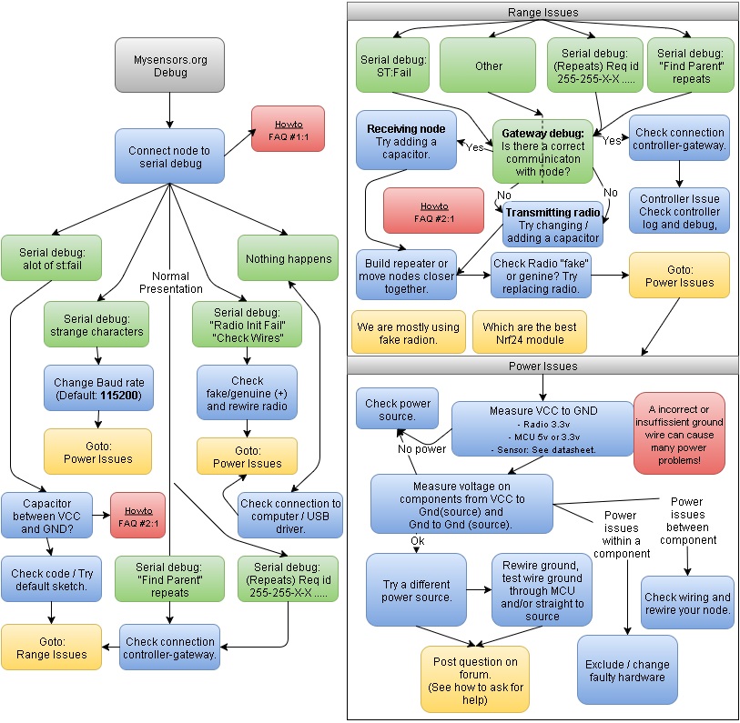
This flowchart shows the most common problems a newcomer may experience. Try to follow the flowchart if you find your problem. Read the most common actions and also read the FAQ below.
FAQ
#1:1 How do I debug my sensors/gateway?
Add #define MY_DEBUG at top of your sketch. Re-flash the sketch and look in the Serial Monitor (default 115200 bps).#2:1 Why should I use a capacitor?
The NRF24L01+ is very sensitive to power spikes. A capacitor will most likely help in smoothing these spikes out. Start with a capacitor of 4.7uF across the radio's 3.3V and GND.#2:2 What does ST:Fail/ST=Fail means?
This means the receiving node or gateway has problems sending ack back to the sending node.
Its probably a hardware issue (power and/or range). Try adding a capacitor (http://www.mysensors.org/build/connect_radio#connecting-a-decoupling-capacitor) to the receiving radio, change powersource, move receiver/sender closer to eachother or build a repeater.#2:3 I get "Radio init fail/!TSM:INIT:TSP FAIL"
Radio init fail means- Not wired correctly
- Not powered correctly
- A nrf24, not a nrf24+
Do you have a capacitor between gnd/vcc on the 3.3v radio? This can make difference... Some reading regarding + and not + Nrf modules.
http://forum.mysensors.org/topic/1153/we-are-mostly-using-fake-nrf24l01-s-but-worse-fakes-are-emerging/4
http://forum.mysensors.org/topic/1664/which-are-the-best-nrf24l01-modules/2#2:4 I only get Find parent in serial log for node
Find parent means the node is trying to find its way to the gateway - and if this repeats it cant.
Its either a range issue or a power issue. You can start by checking the gateway serial log and see if there is any info.
Also, have you added a capacitor on the radios? This is very important since the radio is sensitive to power spikes.It this doesnt work start with changing the power source and check your wirings / ground connection on the node.
Also you can try to move the node closer to the gateway - if this works and you have some distance between node and gateway you should consider a repeater.#3:1 My relay isn't working - why?
- The radio is very power sensitive and it can help adding/changing caps GND/VCC on the radio. 4.7uF is recommended but you can also add higher or lower and even parallel.
- How you wire the ground from the relay can also make a difference. I have had relays jamming when i ran ground trough the Arduino and not straight to source. Also the opposite that it dint work well if I dint have ground through the Arduino.
- Range, when you send a on-command there is a ack going back which needs to be ok ("Error sending command, check device/hardware" message in Domoticz). Follow your serial logs in node and gateway to find out if the radio traffic is ok - and put a repeater in between if necessary.
- Power - I have had Pro Minis that was a little to weak to trigger the relay... :( When the arduino didnt put enough juice out some tries resulted in a unsuccessful relay switch even if the logs told me so. To test this you can upload a sketch doing nothing else but setting the pin to high and low with a delay in between.
Correct log for node (standard relay sketch, node ID = 4) when incoming command from controller.
read: 0-0-4 s=1,c=1,t=2,pt=0,l=1,sg=0:1
send: 4-4-0-0 s=1,c=1,t=2,pt=0,l=1,sg=0,st=ok:1
Incoming change for sensor:1, New status: 1How to ask for help
-
Use a meaningful, specific topic header.
-
Specify your environment:
Arduino IDE version? OS?
Which Arduino Library are you running?
What type of Arduino is your node? Which radio are you using? -
Post the code your having problem with and make sure the code is formatted correctly. You can either enclose the source code in 4 "backtick" characters ```` or write 4 spaces first on each line of code.
-
What is your sensor and gateway debug logs showing? Enable DEBUG in MyConfig.h and look open the Serial Monitor. You can get some hints on how to interpret it here or by using the log parser tool.
-
How do you power your sensor/gateway? The NRF-radios is very sensitive to power spikes and transients. 90% of communication problems can be resolved by replacing a bad transformer or adding a decoupling capacitor to your radio.
-
What are the symptoms? Describe the research and diagnostic steps you've done before asking the question. If possible post an example on how to reproduce the problems you've encountered.
For a more comprehensive guide. Have a look here:
http://www.catb.org/esr/faqs/smart-questions.htmlTroubleshoot the debug output: use the log parser tool.
(courtesy of @martinhjelmare from this thread)
From the source code in the dev branch: link
s = sensor id
c = message type 0-4: presentation, set, req, internal or stream. See link
t = value type: S_VALUE during presentation or V_VALUE during set/req
pt = payload type: string, byte int, etc. See link
l = message length
sg = signed or unsigned message: 0 or 1 for false or true0;0;3;0;9 means node 0 , sensor 0, internal message (3), not an ack message (0), log message (9). This means that it's the gateway that prints this info as a log after already having received the message from a node.
At the end you have the payload: 27
Similarly for a sent message: link
General tip
Start small! If you are having problems with your node - exclude everything (make your code as small as possible) in your sketch and only include the MySensors library. Same for the components - only add minimal needed!
Upload and debug through serial line. Does it work? Great - add ONE function (analogread and one sensor for example). Upload and debug through serial. Continue until you find that it does not work anymore. Now you know which part is causing you trouble. This is much better than trying to debug a big sketch with a lot of functions and components that might interfere with each other. -
Hi Everyone,
I made a quick video to share some of the things I've learned when troubleshooting issues. I’m not an expert and this is by no means an all-inclusive troubleshooting guide but hopefully it will give you some tips that will help you get to the root of the problem you’re experiencing.
-
Troubleshoot the debug output
(courtesy of @martinhjelmare from this thread)
From the source code in the dev branch: link
s = sensor id
c = message type 0-4: presentation, set, req, internal or stream. See link
t = value type: S_VALUE during presentation or V_VALUE during set/req
pt = payload type: string, byte int, etc. See link
l = message length
sg = signed or unsigned message: 0 or 1 for false or true0;0;3;0;9 means node 0 , sensor 0, internal message (3), not an ack message (0), log message (9). This means that it's the gateway that prints this info as a log after already having received the message from a node.
At the end you have the payload: 27
Similarly for a sent message: link
-
For reading debug output for MySensors 2.0 (starts with TSP/TSM), see this great post by @tekka and the doxygen documentation at https://www.mysensors.org/apidocs-beta/group__MyTransportgrp.html#details
EDIT: Or even better, use the awesome online log parser tool.
-
Hi!
Thanks for Your troubleshooting guide. For a newbie (like me) it's really appreciated! :)
A newbie question: Why do You use a 4.7 µF capasitor and on the page for connecting the radio (https://www.mysensors.org/build/connect_radio) they use a 47µF capasitor (10 times bigger)?
/Pellus
-
Hi!
Thanks for Your troubleshooting guide. For a newbie (like me) it's really appreciated! :)
A newbie question: Why do You use a 4.7 µF capasitor and on the page for connecting the radio (https://www.mysensors.org/build/connect_radio) they use a 47µF capasitor (10 times bigger)?
/Pellus
@pellusfromtellus - its a typo... mostly I use a 4.7uF but to be honest im not sure which is the "recommended".
Controller: Proxmox VM - Home Assistant
MySensors GW: Arduino Uno - W5100 Ethernet, Gw Shield Nrf24l01+ 2,4Ghz
MySensors GW: Arduino Uno - Gw Shield RFM69, 433mhz
RFLink GW - Arduino Mega + RFLink Shield, 433mhz -
@pellusfromtellus - its a typo... mostly I use a 4.7uF but to be honest im not sure which is the "recommended".
@sundberg84: Tks for answering! :)
A complete rookie! Love this stuff! My path: Domoticz/Zwave and now a big MySensors-fan! :)
-
@sundberg84: Tks for answering! :)
@pellusfromtellus thanks for noticing. I've updated the connect radio page, hopefully it is a bit clearer now.
@sundberg84 nice profile picture. Great to get a face for you :)
-
I just checked my sensors and I'm using 470µF.
Shows to go you really should check what you grab from a bag of capacitors ;) -
@pellusfromtellus - its a typo... mostly I use a 4.7uF but to be honest im not sure which is the "recommended".
This is old, but I was looking through it today...
According to the datasheets for voltage regulators and the reports of why there are problems with the nRF, the output, or load side capacitors are for keeping the voltage into the nRF as steady as possible. smaller caps are on the front side of the regulators for noise (faster transient voltages than what you'd see on the nRF draw), like those from other electronics, certain lights, radios, etc. and they are ceramic (or other non-polarized) that are great for this filtering in a small package.
The regulators themselves, like the ones in the Arduinos (if you feed RAW pin) take care of the high frequency stuff, but a bigger capacitor is needed for voltage variations, which a ceramic can't do. This is why electrolytics are used. The problem is, electrolytics are much bigger, and so most regulators have you add them to make them work better. But where would you put a component larger than the MCU's chip? And besides, they are getting smaller all the time.
I've never seen anyone say what value cap is overkill, as each person's setup is different. Some don't power their radios from the MCU's rail at all, and some MCUs can be loaded with servos, etc. that would make their draw on transmit different than yours. The bigger the cap (as long as voltage is a tad over what it will see) the better, when it comes to electrolytics. In fact, you can power your MCU with them!
The only way you can know what will work in your unique situation is with an oscilloscope. It is fast enough to capture any dips in voltage on transmit/power-up, and it can show you any noise and ripple on the input. VOMs are just too slow, and not made to measure small changes in a higher voltage at the speeds you will need to see them.
Since I have a pile of 10uf and 100uf, I start with 10uf by default, and if there is any errors that seem like TX dropout, I'll try 100uf, but a cap in this scenario is only a bandaid making up for an under-powered board, IMHO. With battery size/count restrictions, we don't have any choice, but in AC powered systems we should have a PS beefy enough to allow the radio and all peripherals to go nuts without affecting each other.
If you suspect a supply voltage dropout to the nRF, you'll receive fine. So maybe try taking the other peripherals out one by one, maybe measuring overall current draw, and see if the symptom at some point goes away.
And finally, my opinion is that the radio board is the most suspect piece in the chain. Playing musical parts might save you messing with the caps... :) -
Now that encryption is becoming more common, perhaps there can be some tips/flowchart on how to troubleshoot that?
For example, I just discovered that clearing the eeprom (there is a special sketch for that in the examples folder) helps remove old encryption settings.
-
Now that encryption is becoming more common, perhaps there can be some tips/flowchart on how to troubleshoot that?
For example, I just discovered that clearing the eeprom (there is a special sketch for that in the examples folder) helps remove old encryption settings.
-
Like many, I struggled for literally years getting MySensors to work. Recently I tried (yet again) and this time around I began by focussing on an evidence based radio testing method, which for me was the key to success. I humbly cross-link it from here in the hopes that it is helpful to others, because it makes me sad reading how many people have given up trying to get MySensors to work.
Good luck!
And by all means please do not suffer, struggling along in silence. Make a post and try and get some help before frustration mounts too high, and you give up (as I did, many times).
-
Troubleshoot the debug output
(courtesy of @martinhjelmare from this thread)
From the source code in the dev branch: link
s = sensor id
c = message type 0-4: presentation, set, req, internal or stream. See link
t = value type: S_VALUE during presentation or V_VALUE during set/req
pt = payload type: string, byte int, etc. See link
l = message length
sg = signed or unsigned message: 0 or 1 for false or true0;0;3;0;9 means node 0 , sensor 0, internal message (3), not an ack message (0), log message (9). This means that it's the gateway that prints this info as a log after already having received the message from a node.
At the end you have the payload: 27
Similarly for a sent message: link
-
@mfalkvidd what if we replace "s" with "sensorId" and so one?
Hello! It looks like you're interested in this conversation, but you don't have an account yet.
Getting fed up of having to scroll through the same posts each visit? When you register for an account, you'll always come back to exactly where you were before, and choose to be notified of new replies (either via email, or push notification). You'll also be able to save bookmarks and upvote posts to show your appreciation to other community members.
With your input, this post could be even better 💗
Register Login