reporting battery to domoticZ
-
Hi im using at this moment what i had.
270k-100k giving me 1.07 volt at 4.2 batterySo i stay save , but ok reading is not giving my wanted 4.2 volt but around 3.92 volt
My nano is feeded by an dc -dc boost converter giving me 5 volt from this 4.2 battery.
@AWI
Sorry im still a noob in this, just understood how to make a voltage diver using 3:1 divider
.
Could you please give me a simple example how do this calculation.@Rene046 You making it complex. The steps)
- Make sure that the input voltage is within the range of the reference. You did that with the voltage divider (max 1.07 V) :+1:
- set
vRefin the sketch to an expected value (4.2 / 1 , where 1 is the calibration value). You did (4.2/1.07) :+1: - Now you need to calibrate in the software:
- Measure the battery voltage (batteryVoltage) (not the voltage divider) with the multimeter. You did (4.2 Volt) :+1:
- Look at the voltage level reported by the sketch (reportedVoltage). You did (3.92 Volt) :+1:
- Calculate the calibration value and adjust vRef. It needs to report 4.2V now it reports 3.92V so you are off by 1.07. => (4.2/1.07) * 1.07 = 4.2 => set vRef to (4.2/ 1.0) and you will be fine.
There are a few reasons why you need to calibrate:
- The internal reference of the Arduino (1.1V) is not calibrated (can roughly vary from 1V to 1.2V)
- Your voltage divider is not always precise.
- Most multimeters are far more accurate...
-
@Rene046
As I understand correct VBAT_PER_BITS is not just 4.2/1032. This depends what resistors do you use. If you use 1m and 470k VBAT_PER_BITS=0.003363075 made from formula and it will never reads more 3.44v.
#define VMIN and #define VMAX 4.2 used only for formula int batteryPcnt = static_cast<int>(((Vbat-VMIN)/(VMAX-VMIN))*100.);
If you use 270k and 100k maximum is 4.07V so will be VBAT_PER_BITS=0.0039784946236559 and not like in your sketch 0.0041055718475073313782991202346@Arnold-Šlepetis Purist physics ;-) : Although you calculation is probably correct for your use case. I associate a
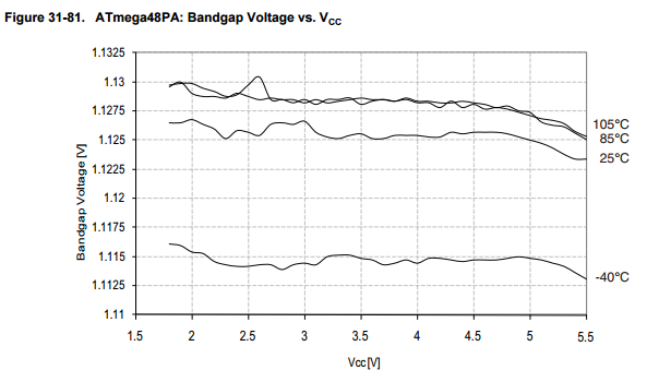
VBAT_PER_BITS=0.0039784946236559with almost atomic precision. As where the internal (band-gap) reference has +- 10% offset and drift with temperature and Vcc (although it is pretty stable for MySensors purposes).
-
What can i do to get a more stable reading now the voltage goes from 3.80 to 4.20 while feeding with an 4.20 volt
-
What can i do to get a more stable reading now the voltage goes from 3.80 to 4.20 while feeding with an 4.20 volt
-
vref: 4.20 V sensorValue: 949 bit 219143 TSF:MSG:SEND,2-2-0-0,s=4,c=1,t=38,pt=7,l=5,sg=0,ft=0,st=OK:3.89 Battery voltage: 3.89 V 219151 TSF:MSG:SEND,2-2-0-0,s=255,c=3,t=0,pt=1,l=1,sg=0,ft=0,st=OK:48 Battery percent: 48 % 219158 MCO:SLP:MS=60000,SMS=0,I1=255,M1=255,I2=255,M2=255 219164 MCO:SLP:TPD 219166 MCO:SLP:WUP=-1 221699 TSF:MSG:SEND,2-2-0-0,s=0,c=1,t=1,pt=7,l=5,sg=0,ft=0,st=OK:35.2 H: 35.20 vref: 4.20 V sensorValue: 951 bit 222708 TSF:MSG:SEND,2-2-0-0,s=4,c=1,t=38,pt=7,l=5,sg=0,ft=0,st=OK:3.90 Battery voltage: 3.90 V 222717 TSF:MSG:SEND,2-2-0-0,s=255,c=3,t=0,pt=1,l=1,sg=0,ft=0,st=OK:50 Battery percent: 50 % 222724 MCO:SLP:MS=60000,SMS=0,I1=255,M1=255,I2=255,M2=255 222731 MCO:SLP:TPD 222733 MCO:SLP:WUP=-1 225242 TSF:MSG:SEND,2-2-0-0,s=1,c=1,t=0,pt=7,l=5,sg=0,ft=0,st=OK:20.6 T: 20.60 225251 TSF:MSG:SEND,2-2-0-0,s=0,c=1,t=1,pt=7,l=5,sg=0,ft=0,st=OK:34.5 H: 34.50 vref: 4.20 V sensorValue: 955 bit 226260 TSF:MSG:SEND,2-2-0-0,s=4,c=1,t=38,pt=7,l=5,sg=0,ft=0,st=OK:3.92 Battery voltage: 3.92 V 226269 TSF:MSG:SEND,2-2-0-0,s=255,c=3,t=0,pt=1,l=1,sg=0,ft=0,st=OK:52 Battery percent: 52 % 226276 MCO:SLP:MS=60000,SMS=0,I1=255,M1=255,I2=255,M2=255 226282 MCO:SLP:TPD -
@Rene046 said in reporting battery to domoticZ:
What can i do to get a more stable reading now the voltage goes from 3.80 to 4.20 while feeding with an 4.20 volt
It seems like when the nano starts reading the voltage drops a bid.
@Rene046 From your earlier postings I can see that you are using a boost converter. Speaking in general these things make a lot of noise on the power line and are certainly not a stable supply.
Just a few considerations:- A nano is not well suited for battery operation. These tend to dissipate at minimum 5mA and will drown a one cell battery fast. Go for a 3.3V pro-mini and remove the led.
- Get rid of the Boost converter and power directly from the battery. The radio and pro-mini will work fine on 3.6V using a regulator (LDO). In this case you can measure battery directly from the Vcc pin without divider.
-
Hi Awi i will build someday if i got it working this project on a pro-mini,.
im not measuring the voltage on the dc-dc booster but on the battery side feeding the converter.
I need this booster because i also feeding my DHT with 5 volt and in future other sensors.BH1750, BMP180, Soil moisture sensor
and im charging my battery in the future with an 6 volt solar panel.
So to see this is working during day time i should be able to read the charging voltage of 4.2 volt and during the night the voltage of battery dropping -
@Rene046 What is the output of the DC=DC converter measuring? Are you powering the nano on the Vcc or Vin pin?
-
Hi Awi i will build someday if i got it working this project on a pro-mini,.
im not measuring the voltage on the dc-dc booster but on the battery side feeding the converter.
I need this booster because i also feeding my DHT with 5 volt and in future other sensors.BH1750, BMP180, Soil moisture sensor
and im charging my battery in the future with an 6 volt solar panel.
So to see this is working during day time i should be able to read the charging voltage of 4.2 volt and during the night the voltage of battery dropping@Rene046 A 3.6-4.2 V battery with 3.3V ldo is perfectly suited to power the sensors you mentioned . I would replace the DHT22 with a (much better) I2C sensor (si7021/ BME280 /... ).
If the measured voltage is not stable then in most cases the power supply or the measured voltage is unstable.
Hello! It looks like you're interested in this conversation, but you don't have an account yet.
Getting fed up of having to scroll through the same posts each visit? When you register for an account, you'll always come back to exactly where you were before, and choose to be notified of new replies (either via email, or push notification). You'll also be able to save bookmarks and upvote posts to show your appreciation to other community members.
With your input, this post could be even better 💗
Register Login