πŸ’¬ Sensebender Gateway


  • Admin

    @meddie

    Is it the standard GatewayW5100 sketch, without modifications, from the mysensors examples?

    If you have done any modifications to the sketch, then please post your modified sketch here.


  • i have only changed the ip adress
    here is the sketch:

    /**
     * The MySensors Arduino library handles the wireless radio link and protocol
     * between your home built sensors/actuators and HA controller of choice.
     * The sensors forms a self healing radio network with optional repeaters. Each
     * repeater and gateway builds a routing tables in EEPROM which keeps track of the
     * network topology allowing messages to be routed to nodes.
     *
     * Created by Henrik Ekblad <henrik.ekblad@mysensors.org>
     * Copyright (C) 2013-2015 Sensnology AB
     * Full contributor list: https://github.com/mysensors/Arduino/graphs/contributors
     *
     * Documentation: http://www.mysensors.org
     * Support Forum: http://forum.mysensors.org
     *
     * This program is free software; you can redistribute it and/or
     * modify it under the terms of the GNU General Public License
     * version 2 as published by the Free Software Foundation.
     *
     *******************************
     *
     * REVISION HISTORY
     * Version 1.0 - Henrik EKblad
     * Contribution by a-lurker and Anticimex,
     * Contribution by Norbert Truchsess <norbert.truchsess@t-online.de>
     * Contribution by Tomas Hozza <thozza@gmail.com>
     *
     *
     * DESCRIPTION
     * The EthernetGateway sends data received from sensors to the ethernet link.
     * The gateway also accepts input on ethernet interface, which is then sent out to the radio network.
     *
     * The GW code is designed for Arduino 328p / 16MHz.  ATmega168 does not have enough memory to run this program.
     *
     * LED purposes:
     * - To use the feature, uncomment MY_DEFAULT_xxx_LED_PIN in the sketch below
     * - RX (green) - blink fast on radio message recieved. In inclusion mode will blink fast only on presentation recieved
     * - TX (yellow) - blink fast on radio message transmitted. In inclusion mode will blink slowly
     * - ERR (red) - fast blink on error during transmission error or recieve crc error
     *
     * See http://www.mysensors.org/build/ethernet_gateway for wiring instructions.
     *
     */
    
    // Enable debug prints to serial monitor
    #define MY_DEBUG
    
    // Enable and select radio type attached
    #define MY_RADIO_NRF24
    //#define MY_RADIO_RFM69
    
    // Enable gateway ethernet module type
    #define MY_GATEWAY_W5100
    
    // W5100 Ethernet module SPI enable (optional if using a shield/module that manages SPI_EN signal)
    //#define MY_W5100_SPI_EN 4
    
    // Enable Soft SPI for NRF radio (note different radio wiring is required)
    // The W5100 ethernet module seems to have a hard time co-operate with
    // radio on the same spi bus.
    #if !defined(MY_W5100_SPI_EN) && !defined(ARDUINO_ARCH_SAMD)
    #define MY_SOFTSPI
    #define MY_SOFT_SPI_SCK_PIN 14
    #define MY_SOFT_SPI_MISO_PIN 16
    #define MY_SOFT_SPI_MOSI_PIN 15
    #endif
    
    // When W5100 is connected we have to move CE/CSN pins for NRF radio
    #ifndef MY_RF24_CE_PIN
    #define MY_RF24_CE_PIN 5
    #endif
    #ifndef MY_RF24_CS_PIN
    #define MY_RF24_CS_PIN 6
    #endif
    
    // Enable to UDP
    //#define MY_USE_UDP
    
    #define MY_IP_ADDRESS 10,0,0,253   // If this is disabled, DHCP is used to retrieve address
    // Renewal period if using DHCP
    //#define MY_IP_RENEWAL_INTERVAL 60000
    // The port to keep open on node server mode / or port to contact in client mode
    #define MY_PORT 5003
    
    // Controller ip address. Enables client mode (default is "server" mode).
    // Also enable this if MY_USE_UDP is used and you want sensor data sent somewhere.
    //#define MY_CONTROLLER_IP_ADDRESS 192, 168, 178, 254
    
    // The MAC address can be anything you want but should be unique on your network.
    // Newer boards have a MAC address printed on the underside of the PCB, which you can (optionally) use.
    // Note that most of the Ardunio examples use  "DEAD BEEF FEED" for the MAC address.
    #define MY_MAC_ADDRESS 0xDE, 0xAD, 0xBE, 0xEF, 0xFE, 0xED
    
    // Enable inclusion mode
    #define MY_INCLUSION_MODE_FEATURE
    // Enable Inclusion mode button on gateway
    //#define MY_INCLUSION_BUTTON_FEATURE
    // Set inclusion mode duration (in seconds)
    #define MY_INCLUSION_MODE_DURATION 60
    // Digital pin used for inclusion mode button
    //#define MY_INCLUSION_MODE_BUTTON_PIN  3
    
    // Set blinking period
    #define MY_DEFAULT_LED_BLINK_PERIOD 300
    
    // Flash leds on rx/tx/err
    // Uncomment to override default HW configurations
    //#define MY_DEFAULT_ERR_LED_PIN 7  // Error led pin
    //#define MY_DEFAULT_RX_LED_PIN  8  // Receive led pin
    //#define MY_DEFAULT_TX_LED_PIN  9  // Transmit led pin
    
    
    #if defined(MY_USE_UDP)
    #include <EthernetUdp.h>
    #endif
    #include <Ethernet.h>
    #include <MySensors.h>
    
    
    void setup()
    {
    }
    
    void loop()
    {
    }```


  • So I think i have a maybe already solved issue, but I can not get int working...
    In Arduino IDE 1.8.1 this is the error during compiling:

    "Local\Arduino15\packages\arduino\hardware\samd\1.6.12\cores\arduino/Arduino.h:48:17: fatal error: sam.h: No such file or directory"

    • I have the MySensors SAMD boards installed, so Sensbender Gateway is availabe

    • Arduino SAMD boards are also installed

    • I have installed the "M0" boards

    • Running windows 10 so no need for the inf file, is this correct?

    what am I missing?

    thanks in advance!


  • Admin

    @jeti SAMD board defs 1.6.12 are currently not supported (PR filed) - you need to downgrade to 1.6.11 until the PR is merged.


  • @tekka thanks! that did the trick!


  • Admin

    @jeti MySensors SAMD board defs updated to 1.0.5, supporting SAMD board defs 1.6.12


  • Contest Winner

    It's has been a long time since I've posted on this forum.Today I received a note form the postal service that a package from a foreign country has arrived at my local postal office. Can't wait until tomorrow, just to see this beauty.

    Now I have to find some time to get it running ;-(


  • Admin

    @TheoL yeah, almost 4mo ago - good to have you back πŸ‘


  • Contest Winner

    @tekka life is really busy. But I'm working on some new MySensors idea's I'd like to try out. But for now on my way to the postal office. Can't wait.


  • Is there any way of getting the MQTT Ethernet gateway working on this yet?


  • Admin

    @tmn103

    I haven't tried myself, but it should be the standard GatewayW5100MQTTClient sketch, without modifications. (the GatewayW5100 sketch is running without modifications already)


  • Just tried the MQTT gateway sketch and got some strange behaviour.

    Seems to pick up one of the nodes, but can't get an ip address or mqtt connection.

    Any ideas on what to try?

    0;255;3;0;9;MCO:BGN:STP
    0;255;3;0;9;MCO:BGN:INIT OK,TSP=1
    IP: 0.0.0.0
    0;255;3;0;9;Attempting MQTT connection...
    0;255;3;0;9;TSF:MSG:READ,113-113-0,s=0,c=1,t=0,pt=7,l=5,sg=0:20.8
    0;255;3;0;9;TSF:MSG:READ,113-113-0,s=0,c=1,t=0,pt=7,l=5,sg=0:20.8
    IP: 255.255.255.255
    0;255;3;0;9;Attempting MQTT connection...
    IP: 0.0.0.0
    0;255;3;0;9;Attempting MQTT connection...
    IP: 255.255.255.255
    0;255;3;0;9;Attempting MQTT connection...
    IP: 0.0.0.0
    0;255;3;0;9;Attempting MQTT connection...
    IP: 255.255.255.255
    0;255;3;0;9;Attempting MQTT connection...
    IP: 0.0.0.0


  • Still can't get the mqtt gateway to work. Has anybody managed to?


  • Just try standard GatewayW5100MQTTClient sketch. It works fine with RFM69HW
    On your log you seems to have issue with your IP. Just my log :

    0;255;3;0;9;MCO:BGN:STP
    0;255;3;0;9;MCO:BGN:INIT OK,TSP=1
    IP: 192.168.1.47
    0;255;3;0;9;Attempting MQTT connection...
    0;255;3;0;9;MQTT connected
    0;255;3;0;9;Sending message on topic: mygateway1-out/0/255/0/0/18
    0;255;3;0;9;TSF:MSG:READ,15-15-255,s=255,c=3,t=7,pt=0,l=0,sg=0:
    0;255;3;0;9;TSF:MSG:BC
    0;255;3;0;9;TSF:MSG:FPAR REQ,ID=15
    0;255;3;0;9;TSF:PNG:SEND,TO=0
    0;255;3;0;9;TSF:CKU:OK
    0;255;3;0;9;TSF:MSG:GWL OK
    0;255;3;0;9;TSF:MSG:SEND,0-0-15-15,s=255,c=3,t=8,pt=1,l=1,sg=0,ft=0,st=OK:0
    0;255;3;0;9;TSF:MSG:READ,15-15-0,s=255,c=3,t=24,pt=1,l=1,sg=0:1
    0;255;3;0;9;TSF:MSG:PINGED,ID=15,HP=1
    0;255;3;0;9;TSF:MSG:SEND,0-0-15-15,s=255,c=3,t=25,pt=1,l=1,sg=0,ft=0,st=OK:1
    0;255;3;0;9;TSF:MSG:READ,15-15-0,s=3,c=1,t=16,pt=1,l=1,sg=0:1
    0;255;3;0;9;Sending message on topic: mygateway1-out/15/3/1/0/16
    

  • Admin

    @tmn103 said in πŸ’¬ Sensebender Gateway:

    Just tried the MQTT gateway sketch and got some strange behaviour.

    Seems to pick up one of the nodes, but can't get an ip address or mqtt connection.

    Any ideas on what to try?

    IP: 255.255.255.255
    0;255;3;0;9;Attempting MQTT connection...
    IP: 0.0.0.0
    

    I would triple-check the IP addresses that you are using...


  • i have uploaded this securitypersonalizer.ino sketch:

    /*
     * The MySensors Arduino library handles the wireless radio link and protocol
     * between your home built sensors/actuators and HA controller of choice.
     * The sensors forms a self healing radio network with optional repeaters. Each
     * repeater and gateway builds a routing tables in EEPROM which keeps track of the
     * network topology allowing messages to be routed to nodes.
     *
     * Created by Henrik Ekblad <henrik.ekblad@mysensors.org>
     * Copyright (C) 2013-2015 Sensnology AB
     * Full contributor list: https://github.com/mysensors/Arduino/graphs/contributors
     *
     * Documentation: http://www.mysensors.org
     * Support Forum: http://forum.mysensors.org
     *
     * This program is free software; you can redistribute it and/or
     * modify it under the terms of the GNU General Public License
     * version 2 as published by the Free Software Foundation.
     *
     *******************************
     */
    /**
     * @ingroup MySigninggrp
     * @{
     * @file SecurityPersonalizer.ino
     * @brief Security personalization sketch
     *
     * REVISION HISTORY
     *  - See git log (git log libraries/MySensors/examples/SecurityPersonalizer/SecurityPersonalizer.ino)
     */
    
    /**
     * @example SecurityPersonalizer.ino
     * This sketch will personalize either none-volatile memory or ATSHA204A for security functions
     * available in the MySensors library.
     *
     * For ATSHA204A:
     * It will write factory default settings to the configuration zone
     * and then lock it.<br>
     * It will then either<br>
     * -# Generate a random value to use as a key which will be stored in
     * slot 0. The key is printed on UART (115200) in clear text for the user to be
     * able to use it as a user-supplied key in other personalization executions
     * where the same key is needed.
     * -# Use a user-supplied value to use as a key which will be stored in
     * slot 0.
     * Finally it will lock the data zone.
     *
     * By default, no locking is performed. User have to manually enable the flags that
     * turn on the locking. Furthermore, user have to send a SPACE character on serial
     * console when prompted to do any locking. On boards that does not provide UART
     * input it is possible to configure the sketch to skip this confirmation.
     * Default settings use ATSHA204A on @ref MY_SIGNING_ATSHA204_PIN.
     *
     * For Soft signing:
     * It will<br>
     * -# Generate a random value to use as a key which will be stored in EEPROM.
     * The key is printed on UART (115200) in clear text for the user to be ablle to
     * use it as a user-supplied key in other personalization executions where the same
     * key is needed.
     * -# Use a user-supplied value to use as a key which will be stored in EEPROM.
     * -# Generate a random value to use as a serial number which will be stored in EEPROM.
     * The serial number is printed on UART (115200) in clear text for the user to be ablle to
     * use it as a user-supplied serial number in other personalization executions where the
     * serial is needed (typically for a whitelist).
     * -# Use a user-supplied value to use as a serial which will be stored in EEPROM.
     *
     * For Encryption support:
     * -# Generate a random value to use as a AES key which will be stored in EEPROM.
     * The AES key is printed on UART (115200) in clear text for the user to be ablle to
     * use it as a user-supplied AES key in other personalization executions where the
     * AES key is needed (typically for RF encryption).
     * -# Use a user-supplied value to use as a AES key which will be stored in EEPROM.
     *
     * Personalizing EEPROM or ATSHA204A still require the appropriate configuration of the
     * library to actually have an effect. There is no problem personalizing EEPROM and
     * ATSHA204A at the same time. There is however a security risk with using the same
     * data for EEPROM and ATSHA204A so it is recommended to use different serial and HMAC
     * keys on the same device for ATSHA204A vs soft signing settings.
     *
     * Details on personalization procedure is given in @ref personalization.
     */
    
    #include "sha204_library.h"
    #include "sha204_lib_return_codes.h"
    #define MY_CORE_ONLY
    #include <MySensors.h>
    
    // Doxygen specific constructs, not included when built normally
    // This is used to enable disabled macros/definitions to be included in the documentation as well.
    #if DOXYGEN
    #define LOCK_CONFIGURATION
    #define LOCK_DATA
    #define SKIP_KEY_STORAGE
    #define USER_KEY
    #define SKIP_UART_CONFIRMATION
    #define USE_SOFT_SIGNING
    #define STORE_SOFT_KEY
    #define USER_SOFT_KEY
    #define STORE_SOFT_SERIAL
    #define USER_SOFT_SERIAL
    #define STORE_AES_KEY
    #define USER_AES_KEY
    #endif
    
    /**
     * @def LOCK_CONFIGURATION
     * @brief Uncomment this to enable locking the configuration zone.
     *
     * It is still possible to change the key, and this also enable random key generation.
     * @warning BE AWARE THAT THIS PREVENTS ANY FUTURE CONFIGURATION CHANGE TO THE CHIP
     */
    #define LOCK_CONFIGURATION
    
    /**
     * @def LOCK_DATA
     * @brief Uncomment this to enable locking the data zone.
     *
     * It is not required to lock data, key cannot be retrieved anyway, but by locking
     * data, it can be guaranteed that nobody even with physical access to the chip,
     * will be able to change the key.
     * @warning BE AWARE THAT THIS PREVENTS THE KEY TO BE CHANGED
     */
    //#define LOCK_DATA
    
    /**
     * @def SKIP_KEY_STORAGE
     * @brief Uncomment this to skip key storage (typically once key has been written once)
     */
    #define SKIP_KEY_STORAGE
    
    /**
     * @def USER_KEY
     * @brief Uncomment this to skip key generation and use @ref user_key_data as key instead.
     */
    //#define USER_KEY
    
    /**
     * @def SKIP_UART_CONFIRMATION
     * @brief Uncomment this for boards that lack UART
     *
     * @b Important<br> No confirmation will be required for locking any zones with this configuration!
     * Also, key generation is not permitted in this mode as there is no way of presenting the generated key.
     */
    //#define SKIP_UART_CONFIRMATION
    
    /**
     * @def USE_SOFT_SIGNING
     * @brief Uncomment this to store data to EEPROM instead of ATSHA204A
     */
    //#define USE_SOFT_SIGNING
    
    /**
     * @def STORE_SOFT_KEY
     * @brief Uncomment this to store soft HMAC key to EEPROM
     */
    //#define STORE_SOFT_KEY
    
    /**
     * @def USER_SOFT_KEY
     * @brief Uncomment this to skip soft HMAC key generation and use @ref user_soft_key_data as HMAC key instead.
     */
    //#define USER_SOFT_KEY
    
    /**
     * @def STORE_SOFT_SERIAL
     * @brief Uncomment this to store soft serial to EEPROM
     */
    //#define STORE_SOFT_SERIAL
    
    /**
     * @def USER_SOFT_SERIAL
     * @brief Uncomment this to skip soft serial generation and use @ref user_soft_serial as serial instead.
     */
    //#define USER_SOFT_SERIAL
    
    /**
     * @def STORE_AES_KEY
     * @brief Uncomment this to store AES key to EEPROM
     */
    //#define STORE_AES_KEY
    
    /**
     * @def USER_AES_KEY
     * @brief Uncomment this to skip AES key generation and use @ref user_aes_key as key instead.
     */
    //#define USER_AES_KEY
    
    #if defined(SKIP_UART_CONFIRMATION) && !defined(USER_KEY)
    #error You have to define USER_KEY for boards that does not have UART
    #endif
    
    #ifdef USER_KEY
    /** @brief The user-defined HMAC key to use for personalization */
    #define MY_HMAC_KEY 0x00,0x00,0x00,0x00,0x00,0x00,0x00,0x00,0x00,0x00,0x00,0x00,0x00,0x00,0x00,0x00,0x00,0x00,0x00,0x00,0x00,0x00,0x00,0x00,0x00,0x00,0x00,0x00,0x00,0x00,0x00,0x00
    /** @brief The data to store in key slot 0 */
    const uint8_t user_key_data[32] = {MY_HMAC_KEY};
    #endif
    
    #ifdef USER_SOFT_KEY
    /** @brief The user-defined soft HMAC key to use for EEPROM personalization */
    #define MY_SOFT_HMAC_KEY 0x00,0x00,0x00,0x00,0x00,0x00,0x00,0x00,0x00,0x00,0x00,0x00,0x00,0x00,0x00,0x00,0x00,0x00,0x00,0x00,0x00,0x00,0x00,0x00,0x00,0x00,0x00,0x00,0x00,0x00,0x00,0x00
    /** @brief The data to store as soft HMAC key in EEPROM */
    const uint8_t user_soft_key_data[32] = {MY_SOFT_HMAC_KEY};
    #endif
    
    #ifdef USER_SOFT_SERIAL
    /** @brief The user-defined soft serial to use for EEPROM personalization */
    #define MY_SOFT_SERIAL 0x00,0x00,0x00,0x00,0x00,0x00,0x00,0x00,0x00
    /** @brief The data to store as soft serial in EEPROM */
    const uint8_t user_soft_serial[9] = {MY_SOFT_SERIAL};
    #endif
    
    #ifdef USER_AES_KEY
    /** @brief The user-defined AES key to use for EEPROM personalization */
    #define MY_AES_KEY 0x00,0x00,0x00,0x00,0x00,0x00,0x00,0x00,0x00,0x00,0x00,0x00,0x00,0x00,0x00,0x00
    /** @brief The data to store as AES key in EEPROM */
    const uint8_t user_aes_key[16] = {MY_AES_KEY};
    #endif
    
    #ifndef USE_SOFT_SIGNING
    const int sha204Pin = MY_SIGNING_ATSHA204_PIN; //!< The IO pin to use for ATSHA204A
    atsha204Class sha204(sha204Pin);
    #endif
    
    /** @brief Print a error notice and halt the execution */
    void halt()
    {
    	Serial.println(F("Halting!"));
    	while(1);
    }
    
    #ifndef USE_SOFT_SIGNING
    /**
     * @brief Write default configuration and return CRC of the configuration bits
     * @returns CRC over the configuration bits
     */
    uint16_t write_config_and_get_crc()
    {
    	uint16_t crc = 0;
    	uint8_t config_word[4];
    	uint8_t tx_buffer[SHA204_CMD_SIZE_MAX];
    	uint8_t rx_buffer[SHA204_RSP_SIZE_MAX];
    	uint8_t ret_code;
    	bool do_write;
    
    	// We will set default settings from datasheet on all slots. This means that we can use slot 0 for the key
    	// as that slot will not be readable (key will therefore be secure) and slot 8 for the payload digest
    	// calculationon as that slot can be written in clear text even when the datazone is locked.
    	// Other settings which are not relevant are kept as is.
    
    	for (int i=0; i < 88; i += 4) {
    		do_write = true;
    		if (i == 20) {
    			config_word[0] = 0x8F;
    			config_word[1] = 0x80;
    			config_word[2] = 0x80;
    			config_word[3] = 0xA1;
    		} else if (i == 24) {
    			config_word[0] = 0x82;
    			config_word[1] = 0xE0;
    			config_word[2] = 0xA3;
    			config_word[3] = 0x60;
    		} else if (i == 28) {
    			config_word[0] = 0x94;
    			config_word[1] = 0x40;
    			config_word[2] = 0xA0;
    			config_word[3] = 0x85;
    		} else if (i == 32) {
    			config_word[0] = 0x86;
    			config_word[1] = 0x40;
    			config_word[2] = 0x87;
    			config_word[3] = 0x07;
    		} else if (i == 36) {
    			config_word[0] = 0x0F;
    			config_word[1] = 0x00;
    			config_word[2] = 0x89;
    			config_word[3] = 0xF2;
    		} else if (i == 40) {
    			config_word[0] = 0x8A;
    			config_word[1] = 0x7A;
    			config_word[2] = 0x0B;
    			config_word[3] = 0x8B;
    		} else if (i == 44) {
    			config_word[0] = 0x0C;
    			config_word[1] = 0x4C;
    			config_word[2] = 0xDD;
    			config_word[3] = 0x4D;
    		} else if (i == 48) {
    			config_word[0] = 0xC2;
    			config_word[1] = 0x42;
    			config_word[2] = 0xAF;
    			config_word[3] = 0x8F;
    		} else if (i == 52 || i == 56 || i == 60 || i == 64) {
    			config_word[0] = 0xFF;
    			config_word[1] = 0x00;
    			config_word[2] = 0xFF;
    			config_word[3] = 0x00;
    		} else if (i == 68 || i == 72 || i == 76 || i == 80) {
    			config_word[0] = 0xFF;
    			config_word[1] = 0xFF;
    			config_word[2] = 0xFF;
    			config_word[3] = 0xFF;
    		} else {
    			// All other configs are untouched
    			ret_code = sha204.sha204m_read(tx_buffer, rx_buffer, SHA204_ZONE_CONFIG, i);
    			if (ret_code != SHA204_SUCCESS) {
    				Serial.print(F("Failed to read config. Response: "));
    				Serial.println(ret_code, HEX);
    				halt();
    			}
    			// Set config_word to the read data
    			config_word[0] = rx_buffer[SHA204_BUFFER_POS_DATA+0];
    			config_word[1] = rx_buffer[SHA204_BUFFER_POS_DATA+1];
    			config_word[2] = rx_buffer[SHA204_BUFFER_POS_DATA+2];
    			config_word[3] = rx_buffer[SHA204_BUFFER_POS_DATA+3];
    			do_write = false;
    		}
    
    		// Update crc with CRC for the current word
    		crc = sha204.calculateAndUpdateCrc(4, config_word, crc);
    
    		// Write config word
    		if (do_write) {
    			ret_code = sha204.sha204m_execute(SHA204_WRITE, SHA204_ZONE_CONFIG,
    			                                  i >> 2, 4, config_word, 0, NULL, 0, NULL,
    			                                  WRITE_COUNT_SHORT, tx_buffer, WRITE_RSP_SIZE, rx_buffer);
    			if (ret_code != SHA204_SUCCESS) {
    				Serial.print(F("Failed to write config word at address "));
    				Serial.print(i);
    				Serial.print(F(". Response: "));
    				Serial.println(ret_code, HEX);
    				halt();
    			}
    		}
    	}
    	return crc;
    }
    
    /**
     * @brief Write provided key to slot 0
     * @param key The key data to write
     */
    void write_key(uint8_t* key)
    {
    	uint8_t tx_buffer[SHA204_CMD_SIZE_MAX];
    	uint8_t rx_buffer[SHA204_RSP_SIZE_MAX];
    	uint8_t ret_code;
    
    	// Write key to slot 0
    	ret_code = sha204.sha204m_execute(SHA204_WRITE, SHA204_ZONE_DATA | SHA204_ZONE_COUNT_FLAG,
    	                                  0, SHA204_ZONE_ACCESS_32, key, 0, NULL, 0, NULL,
    	                                  WRITE_COUNT_LONG, tx_buffer, WRITE_RSP_SIZE, rx_buffer);
    	if (ret_code != SHA204_SUCCESS) {
    		Serial.print(F("Failed to write key to slot 0. Response: "));
    		Serial.println(ret_code, HEX);
    		halt();
    	}
    }
    #endif // not USE_SOFT_SIGNING
    
    /** @brief Dump current configuration to UART */
    void dump_configuration()
    {
    	uint8_t buffer[32];
    #ifndef USE_SOFT_SIGNING
    	Serial.println(F("EEPROM DATA:"));
    #endif
    	hwReadConfigBlock((void*)buffer, (void*)EEPROM_SIGNING_SOFT_HMAC_KEY_ADDRESS, 32);
    	Serial.print(F("SOFT_HMAC_KEY | "));
    	for (int j=0; j<32; j++) {
    		if (buffer[j] < 0x10) {
    			Serial.print('0'); // Because Serial.print does not 0-pad HEX
    		}
    		Serial.print(buffer[j], HEX);
    	}
    	Serial.println();
    	hwReadConfigBlock((void*)buffer, (void*)EEPROM_SIGNING_SOFT_SERIAL_ADDRESS, 9);
    	Serial.print(F("SOFT_SERIAL   | "));
    	for (int j=0; j<9; j++) {
    		if (buffer[j] < 0x10) {
    			Serial.print('0'); // Because Serial.print does not 0-pad HEX
    		}
    		Serial.print(buffer[j], HEX);
    	}
    	Serial.println();
    	hwReadConfigBlock((void*)buffer, (void*)EEPROM_RF_ENCRYPTION_AES_KEY_ADDRESS, 16);
    	Serial.print(F("AES_KEY       | "));
    	for (int j=0; j<16; j++) {
    		if (buffer[j] < 0x10) {
    			Serial.print('0'); // Because Serial.print does not 0-pad HEX
    		}
    		Serial.print(buffer[j], HEX);
    	}
    	Serial.println();
    #ifndef USE_SOFT_SIGNING
    	uint8_t tx_buffer[SHA204_CMD_SIZE_MAX];
    	uint8_t rx_buffer[SHA204_RSP_SIZE_MAX];
    	uint8_t ret_code;
    	Serial.println(F("ATSHA204A DATA:"));
    	for (int i=0; i < 88; i += 4) {
    		ret_code = sha204.sha204m_read(tx_buffer, rx_buffer, SHA204_ZONE_CONFIG, i);
    		if (ret_code != SHA204_SUCCESS) {
    			Serial.print(F("Failed to read config. Response: "));
    			Serial.println(ret_code, HEX);
    			halt();
    		}
    		if (i == 0x00) {
    			Serial.print(F("           SN[0:1]           |         SN[2:3]           | "));
    			for (int j=0; j<4; j++) {
    				if (rx_buffer[SHA204_BUFFER_POS_DATA+j] < 0x10) {
    					Serial.print('0'); // Because Serial.print does not 0-pad HEX
    				}
    				Serial.print(rx_buffer[SHA204_BUFFER_POS_DATA+j], HEX);
    				if (j == 1) {
    					Serial.print(F(" | "));
    				} else {
    					Serial.print(F("   "));
    				}
    			}
    			Serial.println();
    		} else if (i == 0x04) {
    			Serial.print(F("                          Revnum                         | "));
    			for (int j=0; j<4; j++) {
    				if (rx_buffer[SHA204_BUFFER_POS_DATA+j] < 0x10) {
    					Serial.print('0'); // Because Serial.print does not 0-pad HEX
    				}
    				Serial.print(rx_buffer[SHA204_BUFFER_POS_DATA+j], HEX);
    				Serial.print(F("   "));
    			}
    			Serial.println();
    		} else if (i == 0x08) {
    			Serial.print(F("                          SN[4:7]                        | "));
    			for (int j=0; j<4; j++) {
    				if (rx_buffer[SHA204_BUFFER_POS_DATA+j] < 0x10) {
    					Serial.print('0'); // Because Serial.print does not 0-pad HEX
    				}
    				Serial.print(rx_buffer[SHA204_BUFFER_POS_DATA+j], HEX);
    				Serial.print(F("   "));
    			}
    			Serial.println();
    		} else if (i == 0x0C) {
    			Serial.print(F("    SN[8]    |  Reserved13   | I2CEnable | Reserved15    | "));
    			for (int j=0; j<4; j++) {
    				if (rx_buffer[SHA204_BUFFER_POS_DATA+j] < 0x10) {
    					Serial.print('0'); // Because Serial.print does not 0-pad HEX
    				}
    				Serial.print(rx_buffer[SHA204_BUFFER_POS_DATA+j], HEX);
    				if (j < 3) {
    					Serial.print(F(" | "));
    				} else {
    					Serial.print(F("   "));
    				}
    			}
    			Serial.println();
    		} else if (i == 0x10) {
    			Serial.print(F("  I2CAddress |  TempOffset   |  OTPmode  | SelectorMode  | "));
    			for (int j=0; j<4; j++) {
    				if (rx_buffer[SHA204_BUFFER_POS_DATA+j] < 0x10) {
    					Serial.print('0'); // Because Serial.print does not 0-pad HEX
    				}
    				Serial.print(rx_buffer[SHA204_BUFFER_POS_DATA+j], HEX);
    				if (j < 3) {
    					Serial.print(F(" | "));
    				} else {
    					Serial.print(F("   "));
    				}
    			}
    			Serial.println();
    		} else if (i == 0x14) {
    			Serial.print(F("         SlotConfig00        |       SlotConfig01        | "));
    			for (int j=0; j<4; j++) {
    				if (rx_buffer[SHA204_BUFFER_POS_DATA+j] < 0x10) {
    					Serial.print('0'); // Because Serial.print does not 0-pad HEX
    				}
    				Serial.print(rx_buffer[SHA204_BUFFER_POS_DATA+j], HEX);
    				if (j == 1) {
    					Serial.print(F(" | "));
    				} else {
    					Serial.print(F("   "));
    				}
    			}
    			Serial.println();
    		} else if (i == 0x18) {
    			Serial.print(F("         SlotConfig02        |       SlotConfig03        | "));
    			for (int j=0; j<4; j++) {
    				if (rx_buffer[SHA204_BUFFER_POS_DATA+j] < 0x10) {
    					Serial.print('0'); // Because Serial.print does not 0-pad HEX
    				}
    				Serial.print(rx_buffer[SHA204_BUFFER_POS_DATA+j], HEX);
    				if (j == 1) {
    					Serial.print(F(" | "));
    				} else {
    					Serial.print(F("   "));
    				}
    			}
    			Serial.println();
    		} else if (i == 0x1C) {
    			Serial.print(F("         SlotConfig04        |       SlotConfig05        | "));
    			for (int j=0; j<4; j++) {
    				if (rx_buffer[SHA204_BUFFER_POS_DATA+j] < 0x10) {
    					Serial.print('0'); // Because Serial.print does not 0-pad HEX
    				}
    				Serial.print(rx_buffer[SHA204_BUFFER_POS_DATA+j], HEX);
    				if (j == 1) {
    					Serial.print(F(" | "));
    				} else {
    					Serial.print(F("   "));
    				}
    			}
    			Serial.println();
    		} else if (i == 0x20) {
    			Serial.print(F("         SlotConfig06        |       SlotConfig07        | "));
    			for (int j=0; j<4; j++) {
    				if (rx_buffer[SHA204_BUFFER_POS_DATA+j] < 0x10) {
    					Serial.print('0'); // Because Serial.print does not 0-pad HEX
    				}
    				Serial.print(rx_buffer[SHA204_BUFFER_POS_DATA+j], HEX);
    				if (j == 1) {
    					Serial.print(F(" | "));
    				} else {
    					Serial.print(F("   "));
    				}
    			}
    			Serial.println();
    		} else if (i == 0x24) {
    			Serial.print(F("         SlotConfig08        |       SlotConfig09        | "));
    			for (int j=0; j<4; j++) {
    				if (rx_buffer[SHA204_BUFFER_POS_DATA+j] < 0x10) {
    					Serial.print('0'); // Because Serial.print does not 0-pad HEX
    				}
    				Serial.print(rx_buffer[SHA204_BUFFER_POS_DATA+j], HEX);
    				if (j == 1) {
    					Serial.print(F(" | "));
    				} else {
    					Serial.print(F("   "));
    				}
    			}
    			Serial.println();
    		} else if (i == 0x28) {
    			Serial.print(F("         SlotConfig0A        |       SlotConfig0B        | "));
    			for (int j=0; j<4; j++) {
    				if (rx_buffer[SHA204_BUFFER_POS_DATA+j] < 0x10) {
    					Serial.print('0'); // Because Serial.print does not 0-pad HEX
    				}
    				Serial.print(rx_buffer[SHA204_BUFFER_POS_DATA+j], HEX);
    				if (j == 1) {
    					Serial.print(F(" | "));
    				} else {
    					Serial.print(F("   "));
    				}
    			}
    			Serial.println();
    		} else if (i == 0x2C) {
    			Serial.print(F("         SlotConfig0C        |       SlotConfig0D        | "));
    			for (int j=0; j<4; j++) {
    				if (rx_buffer[SHA204_BUFFER_POS_DATA+j] < 0x10) {
    					Serial.print('0'); // Because Serial.print does not 0-pad HEX
    				}
    				Serial.print(rx_buffer[SHA204_BUFFER_POS_DATA+j], HEX);
    				if (j == 1) {
    					Serial.print(F(" | "));
    				} else {
    					Serial.print(F("   "));
    				}
    			}
    			Serial.println();
    		} else if (i == 0x30) {
    			Serial.print(F("         SlotConfig0E        |       SlotConfig0F        | "));
    			for (int j=0; j<4; j++) {
    				if (rx_buffer[SHA204_BUFFER_POS_DATA+j] < 0x10) {
    					Serial.print('0'); // Because Serial.print does not 0-pad HEX
    				}
    				Serial.print(rx_buffer[SHA204_BUFFER_POS_DATA+j], HEX);
    				if (j == 1) {
    					Serial.print(F(" | "));
    				} else {
    					Serial.print(F("   "));
    				}
    			}
    			Serial.println();
    		} else if (i == 0x34) {
    			Serial.print(F("  UseFlag00  | UpdateCount00 | UseFlag01 | UpdateCount01 | "));
    			for (int j=0; j<4; j++) {
    				if (rx_buffer[SHA204_BUFFER_POS_DATA+j] < 0x10) {
    					Serial.print('0'); // Because Serial.print does not 0-pad HEX
    				}
    				Serial.print(rx_buffer[SHA204_BUFFER_POS_DATA+j], HEX);
    				if (j < 3) {
    					Serial.print(F(" | "));
    				} else {
    					Serial.print(F("   "));
    				}
    			}
    			Serial.println();
    		} else if (i == 0x38) {
    			Serial.print(F("  UseFlag02  | UpdateCount02 | UseFlag03 | UpdateCount03 | "));
    			for (int j=0; j<4; j++) {
    				if (rx_buffer[SHA204_BUFFER_POS_DATA+j] < 0x10) {
    					Serial.print('0'); // Because Serial.print does not 0-pad HEX
    				}
    				Serial.print(rx_buffer[SHA204_BUFFER_POS_DATA+j], HEX);
    				if (j < 3) {
    					Serial.print(F(" | "));
    				} else {
    					Serial.print(F("   "));
    				}
    			}
    			Serial.println();
    		} else if (i == 0x3C) {
    			Serial.print(F("  UseFlag04  | UpdateCount04 | UseFlag05 | UpdateCount05 | "));
    			for (int j=0; j<4; j++) {
    				if (rx_buffer[SHA204_BUFFER_POS_DATA+j] < 0x10) {
    					Serial.print('0'); // Because Serial.print does not 0-pad HEX
    				}
    				Serial.print(rx_buffer[SHA204_BUFFER_POS_DATA+j], HEX);
    				if (j < 3) {
    					Serial.print(F(" | "));
    				} else {
    					Serial.print(F("   "));
    				}
    			}
    			Serial.println();
    		} else if (i == 0x40) {
    			Serial.print(F("  UseFlag06  | UpdateCount06 | UseFlag07 | UpdateCount07 | "));
    			for (int j=0; j<4; j++) {
    				if (rx_buffer[SHA204_BUFFER_POS_DATA+j] < 0x10) {
    					Serial.print('0'); // Because Serial.print does not 0-pad HEX
    				}
    				Serial.print(rx_buffer[SHA204_BUFFER_POS_DATA+j], HEX);
    				if (j < 3) {
    					Serial.print(F(" | "));
    				} else {
    					Serial.print(F("   "));
    				}
    			}
    			Serial.println();
    		} else if (i == 0x44) {
    			Serial.print(F("                      LastKeyUse[0:3]                    | "));
    			for (int j=0; j<4; j++) {
    				if (rx_buffer[SHA204_BUFFER_POS_DATA+j] < 0x10) {
    					Serial.print('0'); // Because Serial.print does not 0-pad HEX
    				}
    				Serial.print(rx_buffer[SHA204_BUFFER_POS_DATA+j], HEX);
    				Serial.print(F("   "));
    			}
    			Serial.println();
    		} else if (i == 0x48) {
    			Serial.print(F("                      LastKeyUse[4:7]                    | "));
    			for (int j=0; j<4; j++) {
    				if (rx_buffer[SHA204_BUFFER_POS_DATA+j] < 0x10) {
    					Serial.print('0'); // Because Serial.print does not 0-pad HEX
    				}
    				Serial.print(rx_buffer[SHA204_BUFFER_POS_DATA+j], HEX);
    				Serial.print(F("   "));
    			}
    			Serial.println();
    		} else if (i == 0x4C) {
    			Serial.print(F("                      LastKeyUse[8:B]                    | "));
    			for (int j=0; j<4; j++) {
    				if (rx_buffer[SHA204_BUFFER_POS_DATA+j] < 0x10) {
    					Serial.print('0'); // Because Serial.print does not 0-pad HEX
    				}
    				Serial.print(rx_buffer[SHA204_BUFFER_POS_DATA+j], HEX);
    				Serial.print(F("   "));
    			}
    			Serial.println();
    		} else if (i == 0x50) {
    			Serial.print(F("                      LastKeyUse[C:F]                    | "));
    			for (int j=0; j<4; j++) {
    				if (rx_buffer[SHA204_BUFFER_POS_DATA+j] < 0x10) {
    					Serial.print('0'); // Because Serial.print does not 0-pad HEX
    				}
    				Serial.print(rx_buffer[SHA204_BUFFER_POS_DATA+j], HEX);
    				Serial.print(F("   "));
    			}
    			Serial.println();
    		} else if (i == 0x54) {
    			Serial.print(F("  UserExtra  |    Selector   | LockValue |  LockConfig   | "));
    			for (int j=0; j<4; j++) {
    				if (rx_buffer[SHA204_BUFFER_POS_DATA+j] < 0x10) {
    					Serial.print('0'); // Because Serial.print does not 0-pad HEX
    				}
    				Serial.print(rx_buffer[SHA204_BUFFER_POS_DATA+j], HEX);
    				if (j < 3) {
    					Serial.print(F(" | "));
    				} else {
    					Serial.print(F("   "));
    				}
    			}
    			Serial.println();
    		}
    	}
    #endif // not USE_SOFT_SIGNING
    }
    
    /** @brief Sketch setup code */
    void setup()
    {
    	// Delay startup a bit for serial consoles to catch up
    	unsigned long enter = hwMillis();
    	while (hwMillis() - enter < (unsigned long)500);
    #ifndef USE_SOFT_SIGNING
    	uint8_t tx_buffer[SHA204_CMD_SIZE_MAX];
    	uint8_t rx_buffer[SHA204_RSP_SIZE_MAX];
    	uint8_t ret_code;
    	uint8_t lockConfig = 0;
    	uint8_t lockValue = 0;
    	uint16_t crc;
    	(void)crc;
    #else
    	// initialize pseudo-RNG
    	randomSeed(analogRead(MY_SIGNING_SOFT_RANDOMSEED_PIN));
    #endif
    	uint8_t key[32];
    	(void)key;
    
    	Serial.begin(115200);
    	hwInit();
    	Serial.println(F("Personalization sketch for MySensors usage."));
    	Serial.println(F("-------------------------------------------"));
    
    #ifndef USE_SOFT_SIGNING
    	// Wake device before starting operations
    	ret_code = sha204.sha204c_wakeup(rx_buffer);
    	if (ret_code != SHA204_SUCCESS) {
    		Serial.print(F("Failed to wake device. Response: "));
    		Serial.println(ret_code, HEX);
    		halt();
    	}
    	// Read out lock config bits to determine if locking is possible
    	ret_code = sha204.sha204m_read(tx_buffer, rx_buffer, SHA204_ZONE_CONFIG, 0x15<<2);
    	if (ret_code != SHA204_SUCCESS) {
    		Serial.print(F("Failed to determine device lock status. Response: "));
    		Serial.println(ret_code, HEX);
    		halt();
    	} else {
    		lockConfig = rx_buffer[SHA204_BUFFER_POS_DATA+3];
    		lockValue = rx_buffer[SHA204_BUFFER_POS_DATA+2];
    	}
    #endif
    
    #ifdef STORE_SOFT_KEY
    #ifdef USER_SOFT_KEY
    	memcpy(key, user_soft_key_data, 32);
    	Serial.println(F("Using this user supplied soft HMAC key:"));
    #else
    	// Retrieve random value to use as soft HMAC key
    #ifdef USE_SOFT_SIGNING
    	for (int i = 0; i < 32; i++) {
    		key[i] = random(256) ^ micros();
    		unsigned long enter = hwMillis();
    		while (hwMillis() - enter < (unsigned long)2);
    	}
    	Serial.println(F("This value will be stored in EEPROM as soft HMAC key:"));
    #else
    	ret_code = sha204.sha204m_random(tx_buffer, rx_buffer, RANDOM_SEED_UPDATE);
    	if (ret_code != SHA204_SUCCESS) {
    		Serial.print(F("Random key generation failed. Response: "));
    		Serial.println(ret_code, HEX);
    		halt();
    	} else {
    		memcpy(key, rx_buffer+SHA204_BUFFER_POS_DATA, 32);
    	}
    	if (lockConfig == 0x00) {
    		Serial.println(F("This value will be stored in EEPROM as soft HMAC key:"));
    	} else {
    		Serial.println(F("Key is not randomized (configuration not locked):"));
    	}
    #endif // not USE_SOFT_SIGNING
    #endif // not USER_SOFT_KEY
    	Serial.print("#define MY_SOFT_HMAC_KEY ");
    	for (int i=0; i<32; i++) {
    		Serial.print("0x");
    		if (key[i] < 0x10) {
    			Serial.print('0'); // Because Serial.print does not 0-pad HEX
    		}
    		Serial.print(key[i], HEX);
    		if (i < 31) {
    			Serial.print(',');
    		}
    	}
    	Serial.println();
    	hwWriteConfigBlock((void*)key, (void*)EEPROM_SIGNING_SOFT_HMAC_KEY_ADDRESS, 32);
    #endif // STORE_SOFT_KEY
    
    #ifdef STORE_SOFT_SERIAL
    #ifdef USER_SOFT_SERIAL
    	memcpy(key, user_soft_serial, 9);
    	Serial.println(F("Using this user supplied soft serial:"));
    #else
    	// Retrieve random value to use as serial
    #ifdef USE_SOFT_SIGNING
    	for (int i = 0; i < 9; i++) {
    		key[i] = random(256) ^ micros();
    		unsigned long enter = hwMillis();
    		while (hwMillis() - enter < (unsigned long)2);
    	}
    	Serial.println(F("This value will be stored in EEPROM as soft serial:"));
    #else
    	ret_code = sha204.sha204m_random(tx_buffer, rx_buffer, RANDOM_SEED_UPDATE);
    	if (ret_code != SHA204_SUCCESS) {
    		Serial.print(F("Random serial generation failed. Response: "));
    		Serial.println(ret_code, HEX);
    		halt();
    	} else {
    		memcpy(key, rx_buffer+SHA204_BUFFER_POS_DATA, 9);
    	}
    	if (lockConfig == 0x00) {
    		Serial.println(F("This value will be stored in EEPROM as soft serial:"));
    	} else {
    		Serial.println(F("Serial is not randomized (configuration not locked):"));
    	}
    #endif // not USE_SOFT_SIGNING
    #endif // not USER_SOFT_SERIAL
    	Serial.print("#define MY_SOFT_SERIAL ");
    	for (int i=0; i<9; i++) {
    		Serial.print("0x");
    		if (key[i] < 0x10) {
    			Serial.print('0'); // Because Serial.print does not 0-pad HEX
    		}
    		Serial.print(key[i], HEX);
    		if (i < 8) {
    			Serial.print(',');
    		}
    	}
    	Serial.println();
    	hwWriteConfigBlock((void*)key, (void*)EEPROM_SIGNING_SOFT_SERIAL_ADDRESS, 9);
    #endif // STORE_SOFT_SERIAL
    
    #ifdef STORE_AES_KEY
    #ifdef USER_AES_KEY
    	memcpy(key, user_aes_key, 16);
    	Serial.println(F("Using this user supplied AES key:"));
    #else
    	// Retrieve random value to use as key
    #ifdef USE_SOFT_SIGNING
    	for (int i = 0; i < 16; i++) {
    		key[i] = random(256) ^ micros();
    		unsigned long enter = hwMillis();
    		while (hwMillis() - enter < (unsigned long)2);
    	}
    	Serial.println(F("This key will be stored in EEPROM as AES key:"));
    #else
    	ret_code = sha204.sha204m_random(tx_buffer, rx_buffer, RANDOM_SEED_UPDATE);
    	if (ret_code != SHA204_SUCCESS) {
    		Serial.print(F("Random key generation failed. Response: "));
    		Serial.println(ret_code, HEX);
    		halt();
    	} else {
    		memcpy(key, rx_buffer+SHA204_BUFFER_POS_DATA, 32);
    	}
    	if (lockConfig == 0x00) {
    		Serial.println(F("This key will be stored in EEPROM as AES key:"));
    	} else {
    		Serial.println(F("Key is not randomized (configuration not locked):"));
    	}
    	
    .... i have cut the rest of code because its to long to post here complete ...


    but i dont get any output on serial monitor. Do you know whaat is went wrong?
    thanks


  • Contest Winner

    @meddie it is a limitation of the current personalizer that it does not inherit the baud rate from the library settings. It is stuck to 115200. (can be changed of course). It will be fixed in the next personalizer update. Perhaps you expect a different baud rate?
    See

    Serial.begin(115200);


  • yes i have seen this an my console is set to 115200 bauds, but no output


  • Contest Winner

    Hm. Then I don't know what's wrong. I have not yet used that hardware.


  • i just get the output, the serial console must be open while uploading the sketch, immedialty after the upload i see the output.
    But all Keys are FFFFFFF

    SOFT_HMAC_KEY | FFFFFFFFFFFFFFFFFFFFFFFFFFFFFFFFFFFFFFFFFFFFFFFFFFFFFFFFFFFFFFFF
    SOFT_SERIAL   | FFFFFFFFFFFFFFFFFF
    AES_KEY       | FFFFFFFFFFFFFFFFFFFFFFFFFFFFFFFF
    ATSHA204A DATA:


    Why this?


  • Admin

    The personalizer doesn't wait for the usb port to be enumerated / attached. We need to add the following code in the start of setup() (if I remember right)

    While(! Serial()) {} 
    

    But only for devices using native USB (I thought that I had added it already, but I might be wrong)


  • Contest Winner

    @tbowmo ah, I will add that then for samd targets. The personalizer uses MY_CORE_ONLY so your line perhaps is not run.


  • Admin

    @Anticimex
    I think something in the line of

    #if defined(ARDUINO_ARCH_SAMD)
    while (!Serial) {} // halts operation until something attaches to the USB device
    #endif
    

    above, is based on hwInit function in MyHwSAMD.cpp


  • Contest Winner

    @tbowmo Yep, I have already (locally) done this:

    #if defined(ARDUINO_ARCH_SAMD)
    	while(!Serial()); // Wait for USB enumeration before setting up serial device
    #endif
    	Serial.begin(MY_BAUD_RATE);
    

  • Contest Winner

    I have moved the signing specific discussion in this thread here where it belongs.


  • hi all,

    i have some problems to enable encryption on the gateway. When i upload the cleareeprom sketch, the gateway dont clear the eeprom,
    the same problem comes up when i want to set the ENC-Key. Both sketches work with my moteino-gateway and my ProMini-Node, so do i miss something with the SensebenderGW-Config?

    ClearEEPROM:

    #if defined(ARDUINO_ARCH_SAMD)
    while (!Serial) {} // Wait for USB enumeration before setting up serial device
    #endif
      Serial.begin(MY_BAUD_RATE);
    	Serial.println("Started clearing. Please wait...");
    	for (int i=0; i<EEPROM_LOCAL_CONFIG_ADDRESS; i++) {
    		hwWriteConfig(i,0xFF);
    	}
    	Serial.println("Clearing done. You're ready to go!");
    

    Set ENC-Key:

     #if defined(ARDUINO_ARCH_SAMD)
     while (!Serial) {} // Wait for USB enumeration before setting up serial device
     #endif
      Serial.begin(MY_BAUD_RATE);
      Serial.println("Set ENC-Key. Please wait...");
        uint8_t key[32];
        memcpy(key, user_aes_key, 16);
        hwWriteConfigBlock((void*)key, (void*)EEPROM_RF_ENCRYPTION_AES_KEY_ADDRESS, 16);
        Serial.println("Set ENC-Key. Done");
    

  • Contest Winner

    @Fleischtorte we have confirmed a bug in the I2C eeprom management in the samd platform. A fix is in the works.


  • @Anticimex okay, thanks for the fast response πŸ‘


  • @scalz Did you manage to do the 3D case for the PA LNA transceiver for the sensebender gateway please?


  • @Anticimex said in πŸ’¬ Sensebender Gateway:

    MY_CORE_ONLY

    Just curious, what does "MY_CORE_ONLY" do? The library mentioned that it should be enabled " if you want to use core functions without loading the framework" . What are the core functions and what is the framework?


  • Contest Winner

    @ted core functions are things like the HAL and debug logging functionality. Framework means all the presentation message transmissions and handshaking. Basically, MY_CORE_ONLY allow you to leverage the functionality provided by the library without having the library execute things out of your control.


  • Hardware Contributor

    @alexsh1
    woops, yes i made it but forgot the upload. it's now uploaded here https://www.mysensors.org/hardware/sensebender-gateway#design-files

    Enjoy πŸ™‚


  • @scalz Thank you.

    Does anyone have the PA transceiver version with Sensebender Gateway?
    Any feedback please?


  • Admin

    @alexsh1

    If you mean using a nrf24 with lna/pa, with the gateway. Then yes.. I have had it running for some months now.

    Anything in particular that you want to know?


  • @tbowmo yes, that's what I meant
    I am thinking about installing either a normal nrf24l01+ or lna/pa version. I have had some issues with power in the past with the lna/pa transceiver.
    What's your experience? What kind of power supply do you use? How better is the coverage?


  • Admin

    I haven't checked if the coverage is any better with the lna/pa version, compared to standard modules.

    Currently the gateway is connected to a RPI2, which in turn is powered by a 2A powersupply from RS Components

    I haven't had any issues with it yet, but then again.. I mainly receive data from sensor nodes, and not that much sending data to distant nodes from the gateway


  • @tbowmo It is probably not Sensebender topic, but more lna+pa range one.
    I am not sure about my RPi3 as though it is powered by the 3A PSU, I have a USB z-wave stick, three transceivers, one UPS Plco (as HAT) and a 20x4 screen. I lot of power is consumed so not sure adding yet another one. (lna+pa is power hungry during peaks).

    I'll get the nrf24l01+ lna+pa ordered and test the range. In my view rfm69 range is probably better, but I have the rfm69 gateway on moteino with a trace antenna (very small footprint and it is based on ATMega1284P so 128KB sketch flash memory - more than I need).

    @hek - is it the intention to combine rfm69 and nrf24l01+ gateways in one in the future?
    I understand Sensebender GW is ready for it, but it is more a software limitation???
    I am really looking forward to combined GW.
    I also have a separate one for rfm95 so that I can use some remote sensors.


  • Admin

    No, I haven't heard of any near plans in the core team about doing multi radio/sub-network support in 2.0.

    This requires some extra thoughts and would probably only fit on SAMD/ESP nodes.


  • @hek Which is good as the Sensebender GW is based on SAMD! So it is ready to be the first 2-in-1 GW.
    Anyway, keep on doing a great work! I'll patiently wait until the combined GW is there.


  • Ordered from ITEAD. Nice to get rid of this stuff:
    0_1490290480771_IMG_20170323_180333.jpg
    Just nudging anything result in problems. πŸ˜‰
    Time to fire up the 3D-printer.


  • Aaaand, it's up! Very good fit (the box).
    0_1491402196442_IMG_20170405_162045.jpg

    The box on top is just me trying out different colors of the case. πŸ˜‰
    The one on top has better look. Different brands of PLA.


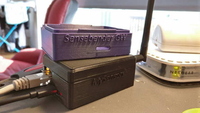
  • @NiklasO that looks very good!

    Are you willing to share your design files with us?
    i just ordered my gateway to get rid of cables and lose components πŸ˜„ a case would really make it complete!


  • Hardware Contributor

    @NiklasO
    great πŸ‘
    @nick-van-alst
    you can get enclosure design files here https://www.mysensors.org/hardware/sensebender-gateway (on page bottom)
    I designed different variants so pick which one you need.


  • @meddie said in πŸ’¬ Sensebender Gateway:

    Ok i just connected the W5100 and NRF24 Module and uploaded the GatewayW5100 Sketch and when the upload is done after reset i dont get any output on serial monitor.
    The orange, green and red led are lighting.

    When i upload the SensebenderGatewaySerial then i get output on serial monitor. It think the problem must be the w5100. But what going wrong?

    @meddie Did you figure out what the problem is? I have exactly the same issue


  • @alexsh1
    hi, yes it was very simple πŸ˜„ the gateway has worked fine in this time, i thought that when nothing shown in serial monitor that the gateway dont work, but it did it, after i connected the gateway to FHEM (my controller) i saw that FHEM connects t mys Gateway.
    So it worked all the time

    Greets Eddie


  • Admin

    @alexsh1

    Have you tried to enable the debug output in the GatewayW5100 example? I think it is disabled by default, due to the limited memory on the small atmega 328p


  • @tbowmo

    Yes, I did

    // Enable debug prints to serial monitor
    #define MY_DEBUG
    #define MY_DEBUG_VERBOSE_SIGNING


  • I am running Arduino IDE 1.8.1 on Windows 10
    Arduino AVR 1.6.18
    Arduino SAMD 1.6.12
    MySensors SAMD 1.0.5

    EDIT: I have tried to upload the default sketch on macbook with Arduino IDE 1.6.2
    It is still the same - no debug info in the terminal


  • OK, I did manage to get debug working partially.
    The gateway reads messages, but does not work as the gateway

    0;255;3;0;9;MCO:BGN:STP
    0;255;3;0;9;MCO:BGN:INIT OK,TSP=1
    0;255;3;0;9;TSF:MSG:READ,10-10-0,s=1,c=1,t=17,pt=5,l=4,sg=0:348
    0;255;3;0;9;TSF:MSG:READ,26-10-0,s=3,c=1,t=24,pt=5,l=4,sg=0:51219479
    0;255;3;0;9;TSF:MSG:READ,10-10-0,s=1,c=1,t=24,pt=5,l=4,sg=0:51219482
    0;255;3;0;9;TSF:MSG:READ,11-11-0,s=2,c=1,t=37,pt=7,l=5,sg=0:1717.62
    0;255;3;0;9;TSF:MSG:READ,11-11-0,s=0,c=1,t=37,pt=7,l=5,sg=0:5338.44
    0;255;3;0;9;TSF:MSG:READ,11-11-0,s=3,c=1,t=37,pt=7,l=5,sg=0:10.75
    0;255;3;0;9;TSF:MSG:READ,11-11-0,s=3,c=1,t=37,pt=7,l=5,sg=0:10.76
    0;255;3;0;9;TSF:MSG:READ,11-11-0,s=4,c=1,t=37,pt=4,l=4,sg=0:880
    0;255;3;0;9;TSF:MSG:READ,6-6-0,s=2,c=1,t=1,pt=7,l=5,sg=0:64.8
    0;255;3;0;9;TSF:MSG:READ,6-6-0,s=0,c=1,t=4,pt=7,l=5,sg=0:1015
    

    I never had a message:

    Gateway startup complete.
    

    EDIT: Self-test with SensebenderSerial sketch gives me this:

    Sensebender GateWay test routine
    Mysensors core version : 2.1.1
    GateWay sketch version : 0.2
    ----------------------------------
    
    - > SHA204 Failed to wakeup SHA204
    - > SD CARD SD CARD did not initialize!
     -> EEPROM PASSED
    -> analog : 38 Failed
    

  • Admin

    @alexsh1

    Could you check the soldering of the samd?

    SD card fails, if you haven't inserted a card, when running the self test.


  • @tbowmo

    I do not have the SD card so that's fine

    The samd looks fine - no bridges etc
    I can try to re-solder it with a hot fan
    Do you think samd may be at fault even though the serial GW is working?

    Unfortunately, I do not have another Ethernet w5100 to try it. Probably have to order a new one


  • Admin

    @alexsh1

    I know that @Anticimex had problems with one of the pre-production samples that we got from China, with various problems, that was solved with "reflowing" the samd with a hot air gun.. So it was just a thought, that it could be a bad solder joint..

    The W5100 is using it's own dedicated SPI port, so even though that the radio works, doesn't mean that there couldn't be any solder problems around the samd pins for W5100.

    We have 3 different SPI ports in use on the gateway, one for the MysX connector, one for radio / sdcard, and one for W5100..


  • @tbowmo I do not have the oven to reflow the whole board, but can mount / unmount or re-work certain components 0805 or 0603. Below this it is a pain in the a***

    Another observation - The GW behaves like this with or without W5100 mounted.
    Seems like an SPI problem to me. How can I wire W5100 to MYSX please and what shall I can in the sketch please? Thank for your help - very much appreciate it


  • Contest Winner

    @alexsh1 The ATSHA is not connected to the SPI and is totally unrelated, so I am also inclined to suspect that perhaps one side of the SAMD is not entirely in contact with the pads. I had to hot-airgun mine to get USB working well but it was an early prototype like @tbowmo said.


  • @tbowmo OK, I manage to find the answer here -

    MYSX
    D11 - MOSI
    D12 - MISO
    D13 - SCK
    D14 -CS

    #define MY_SOFTSPI
    #define MY_SOFT_SPI_SCK_PIN 13
    #define MY_SOFT_SPI_MISO_PIN 12
    #define MY_SOFT_SPI_MOSI_PIN 11
    MY_RF24_CS_PIN 14
    RF24_CE_PIN ???

    Am I correct?


  • My current config for nrf24l01+ and w5100 is as follows:

    #define MY_GATEWAY_W5100
    
    #if !defined(MY_W5100_SPI_EN) && !defined(ARDUINO_ARCH_SAMD)
    #define MY_SOFTSPI
    #define MY_SOFT_SPI_SCK_PIN 14
    #define MY_SOFT_SPI_MISO_PIN 16
    #define MY_SOFT_SPI_MOSI_PIN 15
    #endif
    
    #define MY_RF24_CE_PIN 5
    #define MY_RF24_CS_PIN 6
    

    Why CE / CS pins are 5 and 6?
    Should that be 27 and 3?


  • @tbowmo I have just re-worked SAMD and all the connectors (nrf24l01+ and NET_SPI), but still have the same issue sadly.

    EDIT: If I change to rfm69, the same behavior is observed. It seems that Net_SPI is just not working.


  • Admin

    @alexsh1

    Configuration of the pins are handled by the hardware configuration file, https://github.com/mysensors/ArduinoHwSAMD/blob/master/variants/mysensors_gw/variant.h#L227

    If you look in the gatewayW5100 sketch, the settings for CE / CS pins are enclosed in ifdefs, so they are only used if they are not defined previously.

    If you want to connect the W5100 to the mysx connector, you can change line 174 in the hardware definition file, use SPI2 instead of SPI1 for SPI_ETH

    It could also be a defective W5100 shield? Can you verify that it works on other hardware?


  • @tbowmo Swapping SPIs did not resolve the problem. I am now getting another W5100 to test further.


  • Unfortunately, a new W5100 shield did not work - it seems like a production issue with this sensebender gatewsay as the SPI2 did not work either with W5100.
    Will get a new one ordered.


  • Admin

    Is it possible for you to check the spi wires with a scope? Just to make sure if mosi/miso/ce/Ss lines are toggling as expected?


  • Admin

    Another thing, are you using static ip? If yes, can you ping it? If no, does your DHCP server hand out an ip address?

    Have you tried the basic ethernet examples for the W5100?


  • @tbowmo I am using the static IP and I can ping it, but the "Gateway Ready" message never comes up. Also I can only see the neg24l01+ log (incoming messages only)


  • Admin

    @alexsh1

    If you can ping it, then the W5100 is configured. Something else is wrong..

    One thing that comes to mind, if you compile it as an ethernet GW, then it does not wait for serial console to be active, before initializing the radio. If you compile it as serial GW, then it waits with initialization, until serial is active.

    This means that you probably is missing the GW ready message on the serial port, as it is "sent" before you have an active serial connection.

    Look in MyHwSamd.cpp in the HwInit routine, remove the #ifdef around the while() loop, and try again.


  • @tbowmo Well, if I try the MEGA 2560 with W5100, I get the following:

    0;255;3;0;9;MCO:BGN:INIT GW,CP=RNNGAS-,VER=2.1.1
    0;255;3;0;9;TSM:INIT
    0;255;3;0;9;TSF:WUR:MS=0
    0;255;3;0;9;TSM:INIT:TSP OK
    0;255;3;0;9;TSM:INIT:GW MODE
    0;255;3;0;9;TSM:READY:ID=0,PAR=0,DIS=0
    0;255;3;0;9;MCO:REG:NOT NEEDED
    IP: 10.1.1.120
    0;255;3;0;9;MCO:BGN:STP
    0;255;3;0;9;MCO:BGN:INIT OK,TSP=1
    

    I never get this message with Sensebender GW. I only get

    0;255;3;0;9;TSF:MSG:READ,11-11-0,s=2,c=1,t=37,pt=7,l=5,sg=0:2019.12
    0;255;3;0;9;TSF:MSG:READ,11-11-0,s=0,c=1,t=37,pt=7,l=5,sg=0:6275.51
    0;255;3;0;9;TSF:MSG:READ,11-11-0,s=3,c=1,t=37,pt=7,l=5,sg=0:18.77
    

    or similar messages from nodes.


  • Admin

    @alexsh1

    on atmega2560 you are resetting the device, when you connect a serial terminal to the usb device, so you get all the debug messages on the serial port..

    On SAMD it uses a native USB port, and the chip is not reset when connecting a serial terminal. When using serialGw it will wait until a serial terminal is connected. before initializing radio transport (this is because it does not make sense to have a serial gateway that spits out data to a none existing port).

    When using it as a ethernet gateway, we skip this, as we do not want to wait for a serial terminal, in case you are just using the USB as a power source. So in this mode, it skips the waiting, and just initializes radio gateway etc.

    as stated in my previous message you could look at the MyHwSAMD.cpp file line 73. Remove the #ifdef recompile, upload, and check your serial terminal again.

    Also the log shows that you actually are receiving data from your nodes, so the radio transport is clearly active.. And you can ping your gateways static IP, which means that the W5100 is initialized with the correct IP address.


  • Admin

    @alexsh1

    Did you try my suggestion about hacking the core? Or did you give up on the beast? πŸ™‚

    I'm curious to hear if it is solved..


  • @tbowmo I will try it tomorrow. However, given the amount of time I spent already, I am about to give up...


  • Hello everybody.

    I got my Sensebender gateway yesterday. Have the W5100 Ethernet board mounted and loaded a sketch with the WizNET (W5100) Ethernet module and MQTT.

    The gateway immediately ran as desired.
    Unfortunately only for about 2 hours, then it freezes.
    After a restart it runs again 3 hours and freezes again.
    And so on.

    I wanted to replace an RPI Gatway, which has worked flawlessly for many weeks.

    If the Sensebender gateway works only a few hours it is quite useless.


  • Admin

    @micropet

    It must be a software issue. Are you using it with nrf24? Do you have a github account? If you have, would you mind filling an issue report on the mysensors library? As we need to dig further into this. Please also make a note of how many nodes you have running in your system.


  • Admin

    @alexsh1

    I would really like to get it solved, so it can bring peace to my mind πŸ™‚ so please, if you can..


  • I also think that it is a software problem.

    I use only the RFM96HW.
    My "real" network has 20 nodes.

    The Sensebender gateway has only one DS18b20 node on a seperate frequency.
    (#define MY_RFM69_FREQUENCY (868200000ul))

    And yes, I have a github account and will make an issue report today.


  • @tbowmo I think I am on the right track here. This is the log:

    0;255;3;0;9;MCO:BGN:INIT GW,CP=RNNGS--,VER=2.1.1
    0;255;3;0;9;TSF:LRT:OK
    0;255;3;0;9;TSM:INIT
    0;255;3;0;9;TSF:WUR:MS=0
    0;255;3;0;9;TSM:INIT:TSP OK
    0;255;3;0;9;TSM:INIT:GW MODE
    0;255;3;0;9;TSM:READY:ID=0,PAR=0,DIS=0
    0;255;3;0;9;MCO:REG:NOT NEEDED
    IP: 0.0.0.0
    0;255;3;0;9;MCO:BGN:STP
    0;255;3;0;9;MCO:BGN:INIT OK,TSP=1
    

    The GW Init is correct one, but IP is 0.0.0.0

    This is the sketch:

    // Enable debug prints to serial monitor
    #define MY_DEBUG
    
    // Enable and select radio type attached
    #define MY_RADIO_NRF24
    //#define MY_DEBUG_VERBOSE_RF24
    //#define MY_RADIO_RFM69
    #define MY_RF24_CHANNEL    76
    
    
    // Enable gateway ethernet module type
    #define MY_GATEWAY_W5100
    
    // W5100 Ethernet module SPI enable (optional if using a shield/module that manages SPI_EN signal)
    //#define MY_W5100_SPI_EN 4
    
    // Enable Soft SPI for NRF radio (note different radio wiring is required)
    // The W5100 ethernet module seems to have a hard time co-operate with
    // radio on the same spi bus.
    #if !defined(MY_W5100_SPI_EN) && !defined(ARDUINO_ARCH_SAMD)
    #define MY_SOFTSPI
    #define MY_SOFT_SPI_SCK_PIN 14
    #define MY_SOFT_SPI_MISO_PIN 16
    #define MY_SOFT_SPI_MOSI_PIN 15
    #endif
    
    // When W5100 is connected we have to move CE/CSN pins for NRF radio
    #ifndef MY_RF24_CE_PIN
    #define MY_RF24_CE_PIN 5
    #endif
    #ifndef MY_RF24_CS_PIN
    #define MY_RF24_CS_PIN 6
    #endif
    
    // Enable to UDP
    //#define MY_USE_UDP
    
    #define MY_IP_ADDRESS 10,1,1,150   // If this is disabled, DHCP is used to retrieve address
    // Renewal period if using DHCP
    //#define MY_IP_RENEWAL_INTERVAL 60000
    // The port to keep open on node server mode / or port to contact in client mode
    #define MY_PORT 5003
    
    // Controller ip address. Enables client mode (default is "server" mode).
    // Also enable this if MY_USE_UDP is used and you want sensor data sent somewhere.
    //#define MY_CONTROLLER_IP_ADDRESS 192, 168, 178, 254
    
    // The MAC address can be anything you want but should be unique on your network.
    // Newer boards have a MAC address printed on the underside of the PCB, which you can (optionally) use.
    // Note that most of the Ardunio examples use  "DEAD BEEF FEED" for the MAC address.
    #define MY_MAC_ADDRESS 0xDE, 0xAD, 0xBE, 0xEF, 0xFE, 0xED
    
    // Enable inclusion mode
    #define MY_INCLUSION_MODE_FEATURE
    // Enable Inclusion mode button on gateway
    //#define MY_INCLUSION_BUTTON_FEATURE
    // Set inclusion mode duration (in seconds)
    #define MY_INCLUSION_MODE_DURATION 60
    // Digital pin used for inclusion mode button
    //#define MY_INCLUSION_MODE_BUTTON_PIN  3
    
    // Set blinking period
    #define MY_DEFAULT_LED_BLINK_PERIOD 300
    
    // Flash leds on rx/tx/err
    // Uncomment to override default HW configurations
    //#define MY_DEFAULT_ERR_LED_PIN 7  // Error led pin
    //#define MY_DEFAULT_RX_LED_PIN  8  // Receive led pin
    //#define MY_DEFAULT_TX_LED_PIN  9  // Transmit led pin
    
    
    #if defined(MY_USE_UDP)
    #include <EthernetUdp.h>
    #endif
    #include <Ethernet.h>
    #include <MySensors.h>
    
    
    void setup()
    {
    }
    
    void loop()
    {
    }
    

    I cannot connect to W5100. Tried a different shield with the same result.


  • @tbowmo BTW, I cannot ping it (I suppose there was another network device with the same IP on a network).
    If I try to switch to DHCP I get:

    0;255;3;0;9;MCO:BGN:INIT GW,CP=RNNGS--,VER=2.1.1
    0;255;3;0;9;TSF:LRT:OK
    0;255;3;0;9;TSM:INIT
    0;255;3;0;9;TSF:WUR:MS=0
    0;255;3;0;9;TSM:INIT:TSP OK
    0;255;3;0;9;TSM:INIT:GW MODE
    0;255;3;0;9;TSM:READY:ID=0,PAR=0,DIS=0
    0;255;3;0;9;MCO:REG:NOT NEEDED
    DHCP FAILURE...0;255;3;0;9;!MCO:BGN:TSP FAIL


  • @tbowmo I have received the second GW and I have exactly the same problem. As you suggested, I modified MyHwSAMD.cpp and can see now the start-up message, but there is a problem between the W5100 and GW:

    0;255;3;0;9;660 MCO:BGN:INIT GW,CP=RNNGS---,VER=2.2.0-beta
    0;255;3;0;9;707 TSF:LRT:OK
    0;255;3;0;9;717 TSM:INIT
    0;255;3;0;9;727 TSF:WUR:MS=0
    0;255;3;0;9;742 TSM:INIT:TSP OK
    0;255;3;0;9;752 TSM:INIT:GW MODE
    0;255;3;0;9;762 TSM:READY:ID=0,PAR=0,DIS=0
    0;255;3;0;9;772 MCO:REG:NOT NEEDED
    IP: 0.0.0.0
    0;255;3;0;9;2082 MCO:BGN:STP
    0;255;3;0;9;2092 MCO:BGN:INIT OK,TSP=1
    0;255;3;0;9;17920 TSF:MSG:READ,11-11-0,s=2,c=1,t=37,pt=7,l=5,sg=0:1956.28
    0;255;3;0;9;17931 TSF:MSG:READ,11-11-0,s=0,c=1,t=37,pt=7,l=5,sg=0:6080.20
    0;255;3;0;9;17942 TSF:MSG:READ,11-11-0,s=3,c=1,t=37,pt=7,l=5,sg=0:20.71
    0;255;3;0;9;17953 TSF:MSG:READ,11-11-0,s=1,c=1,t=37,pt=7,l=5,sg=0:13282.11


    I tried different MySensors (stable and dev) and checked solding.
    Now sure what to do now

    EDIT: This is my sketch:

    /**
     * The MySensors Arduino library handles the wireless radio link and protocol
     * between your home built sensors/actuators and HA controller of choice.
     * The sensors forms a self healing radio network with optional repeaters. Each
     * repeater and gateway builds a routing tables in EEPROM which keeps track of the
     * network topology allowing messages to be routed to nodes.
     *
     * Created by Henrik Ekblad <henrik.ekblad@mysensors.org>
     * Copyright (C) 2013-2015 Sensnology AB
     * Full contributor list: https://github.com/mysensors/Arduino/graphs/contributors
     *
     * Documentation: http://www.mysensors.org
     * Support Forum: http://forum.mysensors.org
     *
     * This program is free software; you can redistribute it and/or
     * modify it under the terms of the GNU General Public License
     * version 2 as published by the Free Software Foundation.
     *
     *******************************
     *
     * REVISION HISTORY
     * Version 1.0 - Henrik EKblad
     * Contribution by a-lurker and Anticimex,
     * Contribution by Norbert Truchsess <norbert.truchsess@t-online.de>
     * Contribution by Tomas Hozza <thozza@gmail.com>
     *
     *
     * DESCRIPTION
     * The EthernetGateway sends data received from sensors to the ethernet link.
     * The gateway also accepts input on ethernet interface, which is then sent out to the radio network.
     *
     * The GW code is designed for Arduino 328p / 16MHz.  ATmega168 does not have enough memory to run this program.
     *
     * LED purposes:
     * - To use the feature, uncomment MY_DEFAULT_xxx_LED_PIN in the sketch below
     * - RX (green) - blink fast on radio message recieved. In inclusion mode will blink fast only on presentation recieved
     * - TX (yellow) - blink fast on radio message transmitted. In inclusion mode will blink slowly
     * - ERR (red) - fast blink on error during transmission error or recieve crc error
     *
     * See http://www.mysensors.org/build/ethernet_gateway for wiring instructions.
     *
     */
    
    // Enable debug prints to serial monitor
    #define MY_DEBUG
    //#define MY_DEBUG_VERBOSE_SIGNING
    
    //#define MY_SIGNING_ATSHA204
    //#define MY_SIGNING_REQUEST_SIGNATURES
    
    // Enable and select radio type attached
    #define MY_RADIO_NRF24
    //#define MY_RADIO_RFM69
    
    // Enable gateway ethernet module type
    #define MY_GATEWAY_W5100
    
    // W5100 Ethernet module SPI enable (optional if using a shield/module that manages SPI_EN signal)
    //#define MY_W5100_SPI_EN 4
    
    // Enable Soft SPI for NRF radio (note different radio wiring is required)
    // The W5100 ethernet module seems to have a hard time co-operate with
    // radio on the same spi bus.
    #if !defined(MY_W5100_SPI_EN) && !defined(ARDUINO_ARCH_SAMD)
    #define MY_SOFTSPI
    #define MY_SOFT_SPI_SCK_PIN 14
    #define MY_SOFT_SPI_MISO_PIN 16
    #define MY_SOFT_SPI_MOSI_PIN 15
    #endif
    
    // When W5100 is connected we have to move CE/CSN pins for NRF radio
    #ifndef MY_RF24_CE_PIN
    #define MY_RF24_CE_PIN 5
    #endif
    #ifndef MY_RF24_CS_PIN
    #define MY_RF24_CS_PIN 6
    #endif
    
    // Enable to UDP
    //#define MY_USE_UDP
    
    #define MY_IP_ADDRESS 10,1,1,150   // If this is disabled, DHCP is used to retrieve address
    // Renewal period if using DHCP
    //#define MY_IP_RENEWAL_INTERVAL 60000
    // The port to keep open on node server mode / or port to contact in client mode
    #define MY_PORT 5003
    
    // Controller ip address. Enables client mode (default is "server" mode).
    // Also enable this if MY_USE_UDP is used and you want sensor data sent somewhere.
    //#define MY_CONTROLLER_IP_ADDRESS 192, 168, 178, 254
    
    // The MAC address can be anything you want but should be unique on your network.
    // Newer boards have a MAC address printed on the underside of the PCB, which you can (optionally) use.
    // Note that most of the Ardunio examples use  "DEAD BEEF FEED" for the MAC address.
    #define MY_MAC_ADDRESS 0xDE, 0xAD, 0xBE, 0xEF, 0xFE, 0xED
    
    // Enable inclusion mode
    #define MY_INCLUSION_MODE_FEATURE
    // Enable Inclusion mode button on gateway
    //#define MY_INCLUSION_BUTTON_FEATURE
    // Set inclusion mode duration (in seconds)
    #define MY_INCLUSION_MODE_DURATION 60
    // Digital pin used for inclusion mode button
    //#define MY_INCLUSION_MODE_BUTTON_PIN  3
    
    // Set blinking period
    #define MY_DEFAULT_LED_BLINK_PERIOD 300
    
    // Flash leds on rx/tx/err
    // Uncomment to override default HW configurations
    //#define MY_DEFAULT_ERR_LED_PIN 7  // Error led pin
    //#define MY_DEFAULT_RX_LED_PIN  8  // Receive led pin
    //#define MY_DEFAULT_TX_LED_PIN  9  // Transmit led pin
    
    
    #if defined(MY_USE_UDP)
    #include <EthernetUdp.h>
    #endif
    #include <Ethernet.h>
    #include <MySensors.h>
    
    
    void setup()
    {
    }
    
    void loop()
    {
    }
    

  • Admin

    have you tried the ethernet webserver example sketch (default arduino sketch)?

    Just to rule out mysensors..

    Also, you are using static IP, right? What if you ping that IP address? Do you get a response? If yes, then the W5100 is configured by your sketch, and the connection should be ok between the samd and the ethernet module.


  • @tbowmo ethernet wedserver sketch is giving me this:

    server is at 0.0.0.0
    

    EDIT: I can ping the IP and yes it is static.


  • @tbowmo Do you think softSPI is at fault? What pins shall I use? I tried these

    #define MY_SOFTSPI
    #define MY_SOFT_SPI_SCK_PIN 24 //13 //23  //14
    #define MY_SOFT_SPI_MISO_PIN 22 //14 //22 //16
    #define MY_SOFT_SPI_MOSI_PIN 23 //12 //21 //15


  • @tbowmo I cannot ping it though if I load MySensors GW sketch -
    Destination host unreachable.


  • @tbowmo I have just discovered that the second Ethernet module I have is not W5100 but ENC28J60. Not sure if it is supported by sensebender GW (probably using native Arduino ethernet library?).
    So this module is now being returned and just to figure out any hardware issue I need to order a new W5100


  • Admin

    You should not use soft spi, as there is separate hardware spi ports for radio and W5100.

    If you load the default GatewayW5100 example sketch, then it should work out if the box. Perhaps you need to enable rfm69 instead of nrf24 at the top of the file, but that should be all that is needed.. To get a gateway up and running with W5100


  • Admin

    @alexsh1

    OK, just to recap here, you have a gateway, and a W5100. If you use that combo, and the http server example, you can ping the gateway, and Load the html files in a browser, right?

    If you load stock GatewayW5100 mysensors example sketch, then does that work? (no need to redefine pins for hardware etc, that is handled by the target hardware profile, you choose in arduino)


  • @tbowmo I must admit I have not tried to load files in the browser when trying Ethernet sketch. Only pinging
    Yes, you are correct - gateway, nrf24l01+ and w5100


  • Admin

    @alexsh1

    So gateway with nrf and W5100 is working as it should as an ethernet gateway? Then the W5100 is working with the gateway.

    What is the hardware configuration that you can't get to work? Rfm69 and W5100? Together with the samd GW?

    (just trying to figure out what is going on :))


  • @tbowmo No, sensebender GW is working with nrf24l01+ as a serial GW, but not with W5100 as ethernet GW.

    Interesting observation - I cannot ping the IP any more if I load the ethernet sketch. For your understanding the sensebender GW was never working with W5100 with either nrf or rfm69. Something going wrong around W5100.

    I'll hook up W5100 shield to Arduino nano to test it - I have a suspicion about it. However, even without W5100 connected, sensebender GW is showing IP as 0.0.0.0 (I set IP 10.1.1.150). Why?


  • Admin

    If the ethernet library can't initialize the W5100, it will just write IP address as 0.0.0.0.

    Can you please turn on verbose compile logging in arduino? (file -> Settings, set a checkmark at show verbose output during compilation, and choose "all" in Compiler warnings)

    I just want to make sure that it is using the correct ethernet library.


  • @tbowmo I have verbose on already.
    I think you hit the nail on the head:

    Linking everything together...
    "C:\Users\Alex\AppData\Local\Arduino15\packages\arduino\tools\arm-none-eabi-gcc\4.8.3-2014q1/bin/arm-none-eabi-gcc"  "-LC:\Users\Alex\AppData\Local\Temp\arduino_build_753079" -Os -Wl,--gc-sections -save-temps  "-TC:\Users\Alex\AppData\Local\Arduino15\packages\MySensors\hardware\samd\1.0.5\variants\mysensors_gw/linker_scripts/gcc/flash_with_bootloader.ld" "-Wl,-Map,C:\Users\Alex\AppData\Local\Temp\arduino_build_753079/GatewayW5100.ino.map" --specs=nano.specs --specs=nosys.specs -mcpu=cortex-m0plus -mthumb -Wl,--cref -Wl,--check-sections -Wl,--gc-sections -Wl,--unresolved-symbols=report-all -Wl,--warn-common -Wl,--warn-section-align -o "C:\Users\Alex\AppData\Local\Temp\arduino_build_753079/GatewayW5100.ino.elf" "C:\Users\Alex\AppData\Local\Temp\arduino_build_753079\sketch\GatewayW5100.ino.cpp.o" "C:\Users\Alex\AppData\Local\Temp\arduino_build_753079\libraries\Ethernet\Dhcp.cpp.o" "C:\Users\Alex\AppData\Local\Temp\arduino_build_753079\libraries\Ethernet\Dns.cpp.o" "C:\Users\Alex\AppData\Local\Temp\arduino_build_753079\libraries\Ethernet\Ethernet.cpp.o" "C:\Users\Alex\AppData\Local\Temp\arduino_build_753079\libraries\Ethernet\EthernetClient.cpp.o" "C:\Users\Alex\AppData\Local\Temp\arduino_build_753079\libraries\Ethernet\EthernetServer.cpp.o" "C:\Users\Alex\AppData\Local\Temp\arduino_build_753079\libraries\Ethernet\EthernetUdp.cpp.o" "C:\Users\Alex\AppData\Local\Temp\arduino_build_753079\libraries\Ethernet\utility\socket.cpp.o" "C:\Users\Alex\AppData\Local\Temp\arduino_build_753079\libraries\Ethernet\utility\w5100.cpp.o" "C:\Users\Alex\AppData\Local\Temp\arduino_build_753079\libraries\Wire\Wire.cpp.o" "C:\Users\Alex\AppData\Local\Temp\arduino_build_753079\libraries\SPI\SPI.cpp.o" "C:\Users\Alex\AppData\Local\Temp\arduino_build_753079\core\variant.cpp.o" -Wl,--start-group "-LC:\Users\Alex\AppData\Local\Arduino15\packages\arduino\tools\CMSIS\4.5.0/CMSIS/Lib/GCC/" -larm_cortexM0l_math -lm "C:\Users\Alex\AppData\Local\Temp\arduino_build_753079/core\core.a" -Wl,--end-group
    "C:\Users\Alex\AppData\Local\Arduino15\packages\arduino\tools\arm-none-eabi-gcc\4.8.3-2014q1/bin/arm-none-eabi-objcopy" -O binary  "C:\Users\Alex\AppData\Local\Temp\arduino_build_753079/GatewayW5100.ino.elf" "C:\Users\Alex\AppData\Local\Temp\arduino_build_753079/GatewayW5100.ino.bin"
    "C:\Users\Alex\AppData\Local\Arduino15\packages\arduino\tools\arm-none-eabi-gcc\4.8.3-2014q1/bin/arm-none-eabi-objcopy" -O ihex -R .eeprom  "C:\Users\Alex\AppData\Local\Temp\arduino_build_753079/GatewayW5100.ino.elf" "C:\Users\Alex\AppData\Local\Temp\arduino_build_753079/GatewayW5100.ino.hex"
    Multiple libraries were found for "Ethernet.h"
     Used: C:\Users\Alex\AppData\Local\Arduino15\packages\MySensors\hardware\samd\1.0.5\libraries\Ethernet
     Not used: C:\Program Files (x86)\Arduino\libraries\Ethernet
    Using library Ethernet at version 1.1.2 in folder: C:\Users\Alex\AppData\Local\Arduino15\packages\MySensors\hardware\samd\1.0.5\libraries\Ethernet 
    Using library MySensors at version 2.2.0-beta in folder: C:\Users\Alex\Documents\Arduino\libraries\MySensors 
    Using library Wire at version 1.0 in folder: C:\Users\Alex\AppData\Local\Arduino15\packages\arduino\hardware\samd\1.6.12\libraries\Wire 
    Using library SPI at version 1.0 in folder: C:\Users\Alex\AppData\Local\Arduino15\packages\arduino\hardware\samd\1.6.12\libraries\SPI 
    Sketch uses 45512 bytes (17%) of program storage space. Maximum is 262144 bytes.```

  • Admin

    It is using "our" ethernet driver, which it should be.. The default arduino ethernet driver is hardwired to SERCOM0 for SPI, while we have it on SERCOM1.

    I'll try to bring up one of my own gateways with W5100 later today.


  • Admin

    @alexsh1

    Below is the startup log from my Gateway with W5100 and RFM69 attached:

    0;255;3;0;9;MCO:BGN:INIT GW,CP=RRNGS--,VER=2.2.0-beta
    0;255;3;0;9;TSF:LRT:OK
    0;255;3;0;9;TSM:INIT
    0;255;3;0;9;TSF:WUR:MS=0
    0;255;3;0;9;TSM:INIT:TSP OK
    0;255;3;0;9;TSM:INIT:GW MODE
    0;255;3;0;9;TSM:READY:ID=0,PAR=0,DIS=0
    0;255;3;0;9;MCO:REG:NOT NEEDED
    IP: 192.168.1.66
    0;255;3;0;9;MCO:BGN:STP
    0;255;3;0;9;MCO:BGN:INIT OK,TSP=1
    

    As seen, the W5100 is initialized with ip address,

    Telnet to the Gateway is also working:

    thomas at thomas-ThinkPad-L450 in ~ 
    >telnet 192.168.1.66 5003
    Trying 192.168.1.66...
    Connected to 192.168.1.66.
    Escape character is '^]'.
    200;255;4;0;0;FFFFFFFFFFFFFFFF0300
    200;255;0;0;17;2.2.0-beta
    200;255;3;0;6;0
    200;255;3;0;11;Sensebender Micro
    200;255;3;0;12;1.4
    200;1;0;0;6;
    200;2;0;0;7;
    200;1;1;0;0;23.3
    200;2;1;0;1;46
    200;255;3;0;0;81
    

    The above is with the stock example sketch from mysensors (right now latest development branch though). The only things I changed, was to enable RFM69, instead of NRF24, and set a different IP address, to match my network settings.

    Everything else is running as is, delivered from the mysensors examples..


  • @tbowmo if you take off the W5100 shield, does it still come up with IP please:

    255;3;0;9;MCO:REG:NOT NEEDED
    IP: 192.168.1.66
    

  • Admin

    @alexsh1

    This log is without ethernet shield attached

    0;255;3;0;9;MCO:BGN:INIT GW,CP=RRNGS--,VER=2.2.0-beta
    0;255;3;0;9;TSF:LRT:OK
    0;255;3;0;9;TSM:INIT
    0;255;3;0;9;TSF:WUR:MS=0
    0;255;3;0;9;TSM:INIT:TSP OK
    0;255;3;0;9;TSM:INIT:GW MODE
    0;255;3;0;9;TSM:READY:ID=0,PAR=0,DIS=0
    0;255;3;0;9;MCO:REG:NOT NEEDED
    IP: 0.0.0.0
    0;255;3;0;9;MCO:BGN:STP
    0;255;3;0;9;MCO:BGN:INIT OK,TSP=1


  • @tbowmo Thanks - I am assuming that I have a faulty W5100 shield in this case. Unfortunately, I have received a wrong replacement shield enc28j60 instead of W5100. Do you know if Sensebender GW would work with

    #define MY_GATEWAY_ENC28J60
    

    The one I have does not have AMS1117-3.3 on board and must be fed with 3.3V instead of 5v


  • @tbowmo The problem has been identified. I have used a hot fan to re-sit W5100 on the network shield.
    AND

    0;255;3;0;9;2430 MCO:BGN:INIT GW,CP=RNNGS---,VER=2.2.0-beta
    0;255;3;0;9;2477 TSF:LRT:OK
    0;255;3;0;9;2487 TSM:INIT
    0;255;3;0;9;2497 TSF:WUR:MS=0
    0;255;3;0;9;2512 TSM:INIT:TSP OK
    0;255;3;0;9;2522 TSM:INIT:GW MODE
    0;255;3;0;9;2532 TSM:READY:ID=0,PAR=0,DIS=0
    0;255;3;0;9;2542 MCO:REG:NOT NEEDED
    IP: 10.1.1.200
    0;255;3;0;9;3852 MCO:BGN:STP
    0;255;3;0;9;3862 MCO:BGN:INIT OK,TSP=1
    

    Still cannot ping it, which means there is still a problem with the shield.
    It is of a poor quality and does have multiple bridges around W5100 like this:
    0_1495292173685_HTB1VJAfNFXXXXaGXFXXq6xXFXXXF.jpg

    I found a similar problem here:
    https://electronics.stackexchange.com/questions/156147/are-solder-bridges-on-chips-always-bad

    At least I know where the problem is.
    Thanks @tbowmo


  • Admin

    @alexsh1

    Great, that we found the problem, and thanks for reporting back here on the forum πŸ™‚

    I haven't tried with other ethernet controllers, than the W5100, And the socket for W5100 is supplied with 5V directly.

    Also, I do not know if they are pin compatible?


  • @tbowmo I think they are pin compatible but unfortunately take different voltage. On arduino board, somebody told me that enc28j60 can tolerate 5V. It seems to be the case, as mine survived w5100 socket

    EDIT: From the enc28j60 datasheet

    • Operating Voltage of 3.1V to 3.6V (3.3V typical)
    • 5V Tolerant Input


  • @tbowmo I can confirm now that everything is working fine after I tested the Sensebender GW with the third (yes, third!!!) shield. Thanks Thomas for your help!


  • @tbowmo The pinout is identical.

    W5100
    alt text

    ENC28J60
    alt text

    I can modify ENC28J60 shield (reduce voltage to 3.3V) and test it with the sensebender GW, but it does require hardware mod


  • Question,
    "To use the serial port in the mysx connector, you should use Serial1 in your sketches, as the default Serial is connected to the USB serial device"

    What pins is the serial port in the mysx connector, I see no mention of it other than that line. I want to mirror the serial data sent to my controller via the USB port to the the serial port in the mysx connector that will then be attached to a bluetooth SPP device. Just want another way to view the radio traffic.


  • Admin

    @nitroburn

    Have you seen the documentation for MysX connector: https://www.mysensors.org/hardware/mysx?

    (hint, look for Data To Module, and Data From Module :))


  • Contest Winner

    @tbowmo @nitroburn
    Actually, it is even more clearly specified than that as DTM and DFM means Data To MCU and Data From MCU. "module" is not explicitly defining what "side" you mean. The MCU is clearly defined so DTM and DFM leavs no doubt on the direction and function of the pin.


Log in to reply
 

Suggested Topics

1
Online

11.2k
Users

11.1k
Topics

112.5k
Posts