rboard - Cheap relay/radio/arduino board ~$10
-
Well that was easy....
Loaded up the RelayActuator sketch, changed the relay pin to 4.
It joined Vera as it should, and after providing it a 5V powersource the relay clicks on and off as commanded! -
Now loaded up the Garage Door sketch , choosing A0 for the switch and D4 for the relay and again works straight away!
I note they also have a header for 433Mhz module and according to the schematic, the pads could be used for 5v,GND, and D3 - so could be used for another sensor such as Dallas temp....or ultrasonic/IR..anything!
Great buy for $10
ftp://imall.iteadstudio.com/Mainboard/IM140704001_mini_Rboard/SCH_IM140704001_MiniRboard.pdf
-
Good price but a pity you still need an external 5 Volts supply...
-
Yep no getting away from the need for power! A mains version would be great, but although it only adds a few $ in electronics, getting all the approvals adds $$$. But for DIY'ers adding a phone powersupply is cheap and reasonably compact.
-
Yeah it seems like a really nice board but it could have had access to a few more digital pins on the board.
Is it really only A0 and D3 that can be accessed other then the relay? -
Yeah it seems like a really nice board but it could have had access to a few more digital pins on the board.
Is it really only A0 and D3 that can be accessed other then the relay?@korttoma said:
Yeah it seems like a really nice board but it could have had access to a few more digital pins on the board.
Is it really only A0 and D3 that can be accessed other then the relay?Looks like. Surprising that folks don't at least put a few more pins on solderable holes on boards like this, where you could put a pin or solder a wire - seems easy and takes little space.
-
-
@Homer said:
Which board do I choose when uploading a sketch to this?
It's all good, I found a website which stated what it was compatible with So I'm moving on :-)
Now I am just trying to work out how to connect a switch to the A0 pin. There are two pins so is the switch just bridging the two? Sorry, I really am trying to learn this stuff.
-
Ok, looks like I am slowly getting there :-)
fyi I tried playing around with the above sketch, but it's a no go as Codebender tells me <Bounce2.h> is missing.
-
The link above has been updated to point the MySensors codebender location (where Bounce2 is available).
-
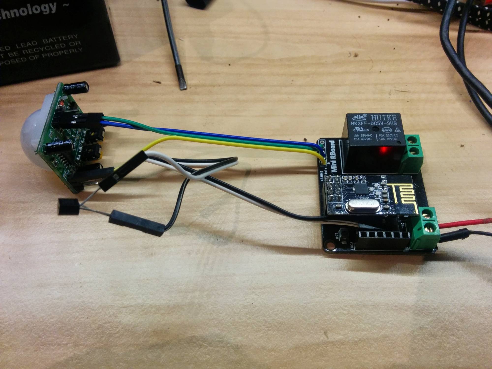
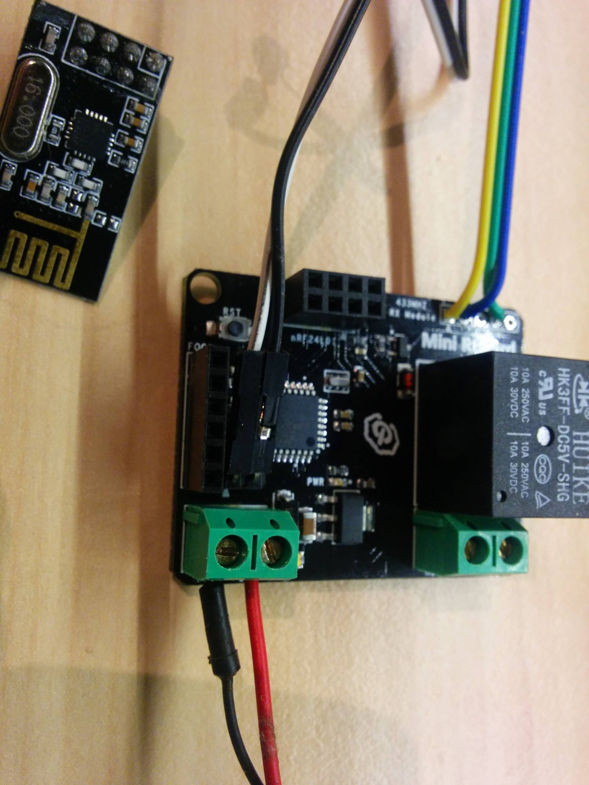
I used one of these boards for a multi sensor recently.... Temp/Motion and Relay actuator.
Turns out to be a very tidy solution !
I'm using the A0 pins connected to a ds18b20 . This is really cute in that the sensor is connected in parasite mode meaning i only need two wires. To do this all you need to do is join pin 1 and 3 to GND and the middle signal wire goes to the A0 ( which is used as D14 ). The rboard also has a 10k resistor from the A0 connection to 3.3v. It works just fine!!
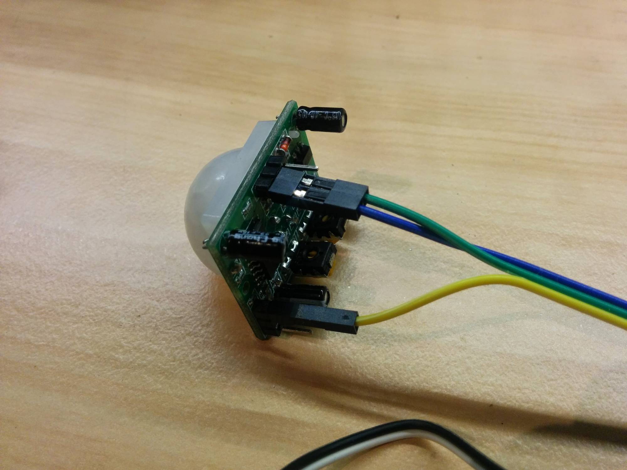
Then for the PIR, im using the readily available RF433 connections to provide D3, 3.3v and GND. The cute trick here is that even though these PIR's are designed for 5v, they run great on 3,3 v too...you just need to connect it differently! See in the photo where the yellow wire which is the 3.3 v vcc supply connects on the PIR sensor.. Genius!!!
See here for background on this:
http://techgurka.blogspot.com.au/2013/05/cheap-pyroelectric-infrared-pir-motion.htmlDo this, feed it 5v ( as relay needs 5v) and you have a tidy little multisensor.
Here's some pics:
full sketch here https://codebender.cc/sketch:61919
-
@gregl I've now my rboard, but I have no Foca, so I used my programmer I matched against the pins on the board.
I choose mini pro 3V3 in the arduino ide but impossible to sync .... is there something I am missing ?
Also, do you change something on initialization as for the 4 switch version ?
thanks,
Hello! It looks like you're interested in this conversation, but you don't have an account yet.
Getting fed up of having to scroll through the same posts each visit? When you register for an account, you'll always come back to exactly where you were before, and choose to be notified of new replies (either via email, or push notification). You'll also be able to save bookmarks and upvote posts to show your appreciation to other community members.
With your input, this post could be even better 💗
Register Login