💬 Button size radionode with sensors swarm extension
-
@alexsh1 said in 💬 Button size radionode with sensors swarm extension:
it on the first day I got
Could you post the code you use? and links for the libs. we will check tomorrow consumption with your code . mysensors 2.0 or 2.2?
@yury It is the latest bh1750 lib -> https://github.com/claws/BH1750
I am using MySensors 2.2.0b
I am using a default code :
https://github.com/EasySensors/ButtonSizeNode/blob/master/ButtonSizeNode.ino -
@yury It is the latest bh1750 lib -> https://github.com/claws/BH1750
I am using MySensors 2.2.0b
I am using a default code :
https://github.com/EasySensors/ButtonSizeNode/blob/master/ButtonSizeNode.ino@yury One thing I did notice is this. To put BH1750 into a sleep mode (1uA consumption), it has to be called as follows:
void setup()  {
lightMeter.begin(BH1750_ONE_TIME_HIGH_RES_MODE);

}
After a one time measurement it goes to sleep automatically.
Please see -> https://github.com/claws/BH1750/blob/master/examples/BH1750advanced/BH1750advanced.inoI have tried above, but still getting 0.14mA consumption in a sleep mode. Very odd!
-
@yury It is the latest bh1750 lib -> https://github.com/claws/BH1750
I am using MySensors 2.2.0b
I am using a default code :
https://github.com/EasySensors/ButtonSizeNode/blob/master/ButtonSizeNode.ino@alexsh1 Very strange. I can't see a method write8 in current lib version (https://github.com/claws/BH1750). So I can't understand how is it possible to compile default code with this string
lightMeter.write8(BH1750_POWER_DOWN);I couldn't put this sensor into power down mode without this.
-
@yury One thing I did notice is this. To put BH1750 into a sleep mode (1uA consumption), it has to be called as follows:
void setup()  {
lightMeter.begin(BH1750_ONE_TIME_HIGH_RES_MODE);

}
After a one time measurement it goes to sleep automatically.
Please see -> https://github.com/claws/BH1750/blob/master/examples/BH1750advanced/BH1750advanced.inoI have tried above, but still getting 0.14mA consumption in a sleep mode. Very odd!
@alexsh1 said in 💬 Button size radionode with sensors swarm extension:
...
After a one time measurement it goes to sleep automatically.
...
I have tried above, but still getting 0.14mA consumption in a sleep mode. Very odd!I've read the claws library briefly again. I'm a litte doubt that this code:
_delay_ms(10);is enough to ensure correctly timings and sensors work :)
-
@alexsh1 Very strange. I can't see a method write8 in current lib version (https://github.com/claws/BH1750). So I can't understand how is it possible to compile default code with this string
lightMeter.write8(BH1750_POWER_DOWN);I couldn't put this sensor into power down mode without this.
@Koresh said in 💬 Button size radionode with sensors swarm extension:
@alexsh1 Very strange. I can't see a method write8 in current lib version (https://github.com/claws/BH1750). So I can't understand how is it possible to compile default code with this string
lightMeter.write8(BH1750_POWER_DOWN);I couldn't put this sensor into power down mode without this.
I tried it with the original (old) library -> https://github.com/mysensors/MySensorsArduinoExamples/tree/master/libraries/BH1750
I commended out "private" in bh1750.h
Consumption has not changed - 0.14mA -
@alexsh1 Very strange. I can't see a method write8 in current lib version (https://github.com/claws/BH1750). So I can't understand how is it possible to compile default code with this string
lightMeter.write8(BH1750_POWER_DOWN);I couldn't put this sensor into power down mode without this.
-
@alexsh1 said in 💬 Button size radionode with sensors swarm extension:
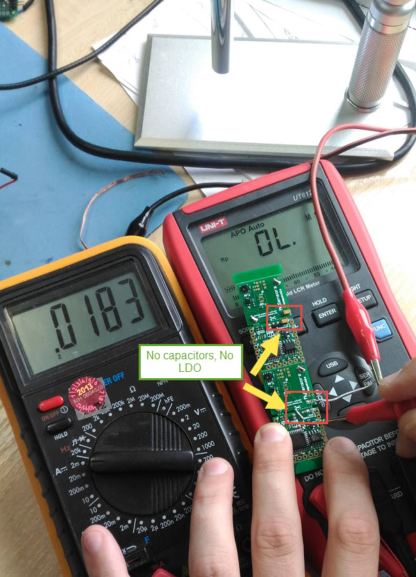
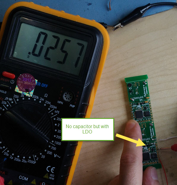
Something else is eating up a few milliamps
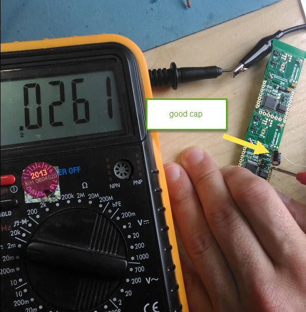
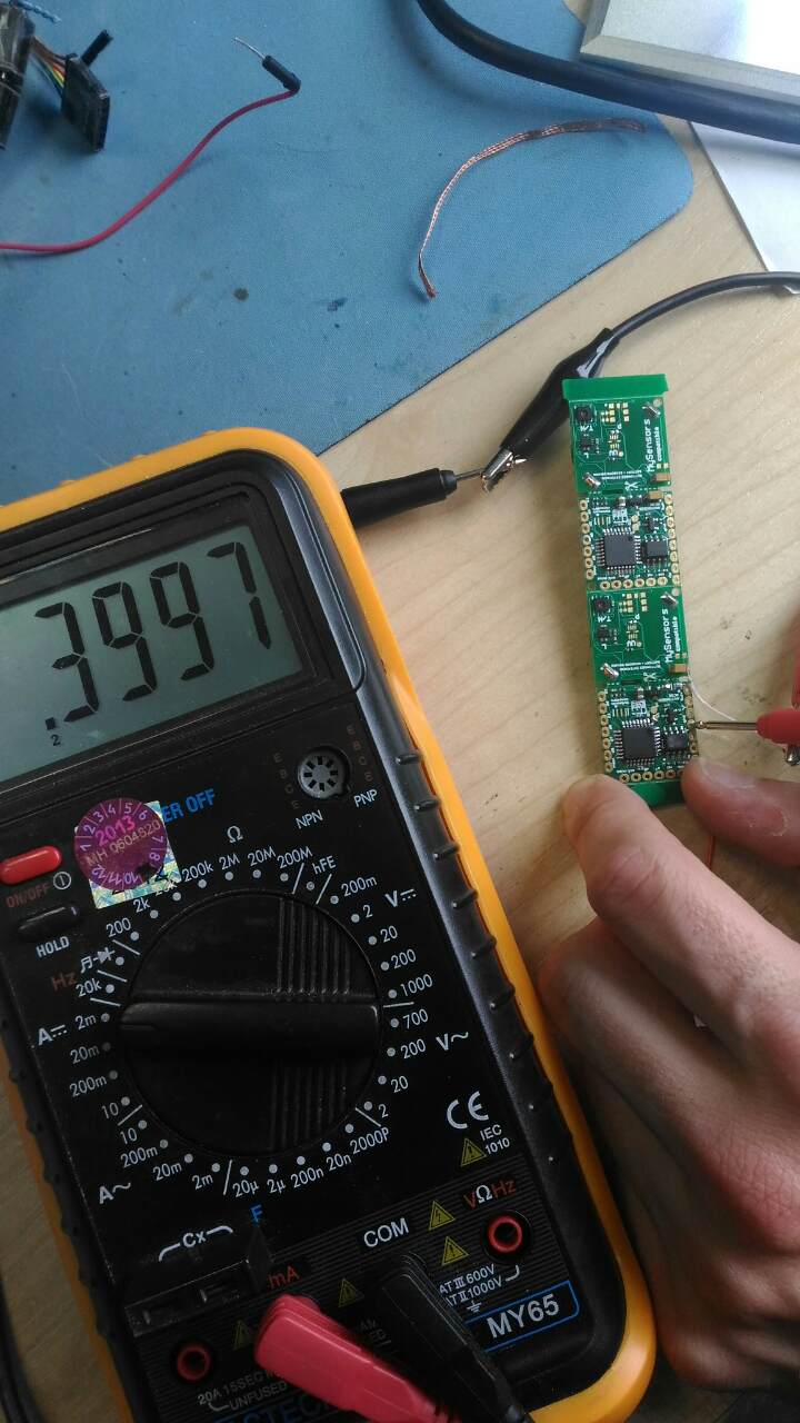
yes seems your board has bad capacitors. After rechecking many boards we found one eating a lot - 0.4 mA. Replacing caps fixed issue.
can you check?
-
@alexsh1 said in 💬 Button size radionode with sensors swarm extension:
Something else is eating up a few milliamps
yes seems your board has bad capacitors. After rechecking many boards we found one eating a lot - 0.4 mA. Replacing caps fixed issue.
can you check?
-
@alexsh1 said in 💬 Button size radionode with sensors swarm extension:
Something else is eating up a few milliamps
yes seems your board has bad capacitors. After rechecking many boards we found one eating a lot - 0.4 mA. Replacing caps fixed issue.
can you check?
-
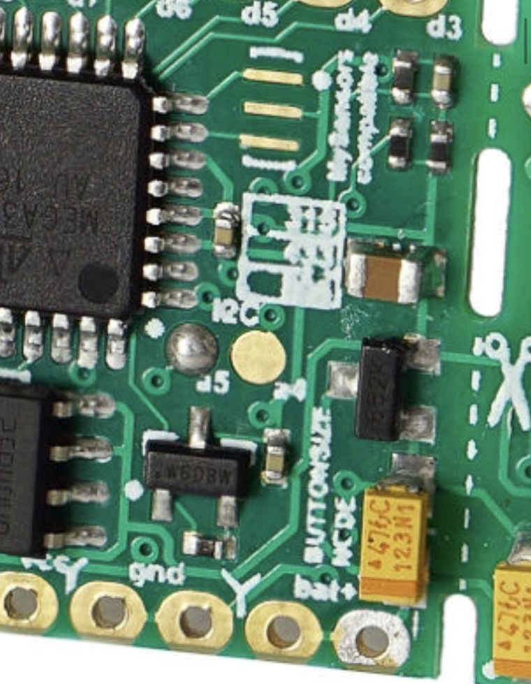
@alexsh1 you can solder one or two capacitors ~50-200uf. But you should remove both because we do not know which of them is bad. Do not forget about polarity ;) Dot-key on the board means positive, so tantalum has positive key, but electrolitic capacitors has negative key.
-
@alexsh1 you can solder one or two capacitors ~50-200uf. But you should remove both because we do not know which of them is bad. Do not forget about polarity ;) Dot-key on the board means positive, so tantalum has positive key, but electrolitic capacitors has negative key.
-
combined capacitance of booth should be 100 --200 microfarads . It is input capacitors.
please try replacing themre:
I was suspecting EEPROM (CS pin with pull-up resistor?) to be a culpritnot pullups...
-
@yury what's your estimate of battery life based on a new consumption of about 25uA and the default sketch?
-
@Koresh thanks. It does not matter which caps, right?
I have a few 1206 100uF ceramic caps. They are not polarised and may be a good fit size wise@alexsh1 There is no problem to use your capacitors. 1206imp = 3216metric (type A) so they are fit perfect :+1:
About consumption... This is quite universal board. If you plan to use CR2032 battery it can be worth to omit LDO. You can do it using existing 0603 jumper footprint near right storage capacitor. -
@yury said in 💬 Button size radionode with sensors swarm extension:
@alexsh1 220 mAh(Duracell) / 0.025 (mA) = 8800 hrs = 366 days.
Not exactly - 25uA is a sleeping current.
There will be sending periods every 10 mins.
So I suppose the lifetime is less than a year -
@alexsh1 There is no problem to use your capacitors. 1206imp = 3216metric (type A) so they are fit perfect :+1:
About consumption... This is quite universal board. If you plan to use CR2032 battery it can be worth to omit LDO. You can do it using existing 0603 jumper footprint near right storage capacitor. -
@yury said in 💬 Button size radionode with sensors swarm extension:
@alexsh1 220 mAh(Duracell) / 0.025 (mA) = 8800 hrs = 366 days.
Not exactly - 25uA is a sleeping current.
There will be sending periods every 10 mins.
So I suppose the lifetime is less than a year@alexsh1 said in 💬 Button size radionode with sensors swarm extension:
@yury said in 💬 Button size radionode with sensors swarm extension:
@alexsh1 220 mAh(Duracell) / 0.025 (mA) = 8800 hrs = 366 days.
Not exactly - 25uA is a sleeping current.
There will be sending periods every 10 mins.
So I suppose the lifetime is less than a yearYes, it is sleeping time estimate. When it wakes up it compares first, like : if ( abs(d) > 50 ) send(msg_vis.set(VIS_LIGHT), true); so it might send or not.
But this is just example sketch and you are very welcome to create pull-request or make suggestion how to improve.
Hello! It looks like you're interested in this conversation, but you don't have an account yet.
Getting fed up of having to scroll through the same posts each visit? When you register for an account, you'll always come back to exactly where you were before, and choose to be notified of new replies (either via email, or push notification). You'll also be able to save bookmarks and upvote posts to show your appreciation to other community members.
With your input, this post could be even better 💗
Register Login