implementing multiple sensors
-
Any help on implementing multiple sensors and readings on one Arduino would be appreciated.
@andyuno
Im really no expert but I'll try to explain with a easy example. So for borked english.Say you want to combine a soil moisture sensor and a DHT22 temp sensor.
Open both of the examples and look at the top part that are circled in red.
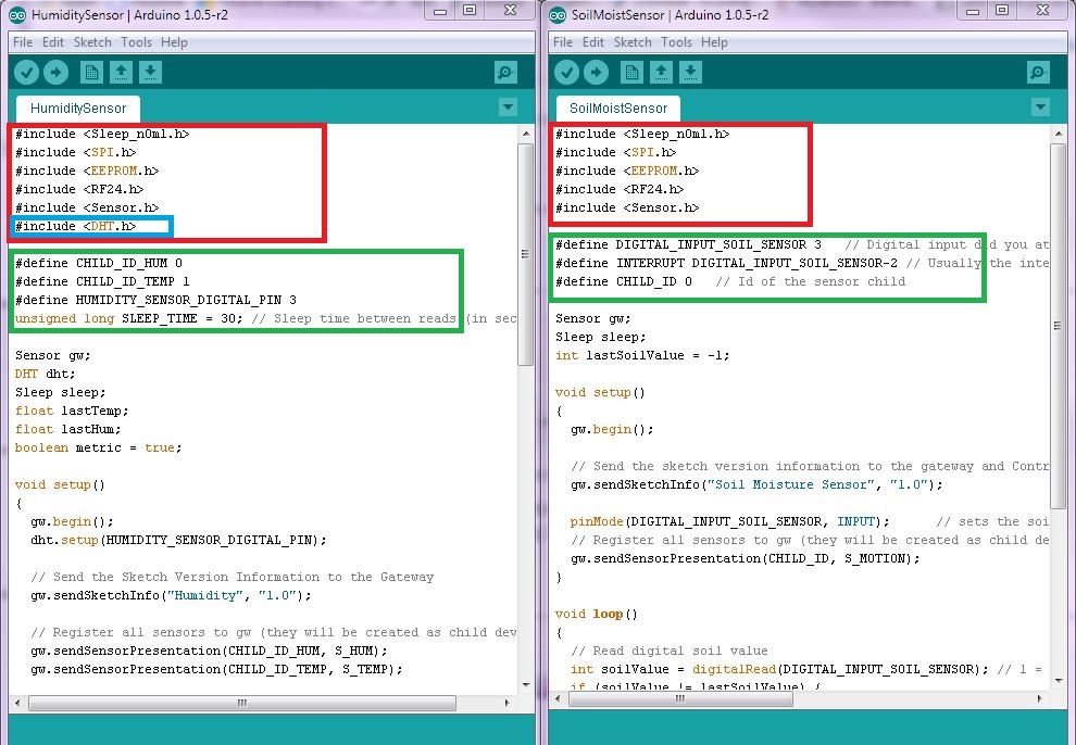
This is where all the librarys that are needed are listed. Simply copy/paste the ones that are needed, in my example all libraries are equal except for the one circled in blue. So make sure you get all needed libraries!
The next step is to look at the define part, circled in green. Here you copy/paste so you get all the needed parts and you must also change the pin number where your sensor is connected on the Arduino bord. So if you soldered your soil sensor on digital pin 5, change the number from 3 to 5 in #define DIGITAL_INPUT_SOIL_SENSOR 3.
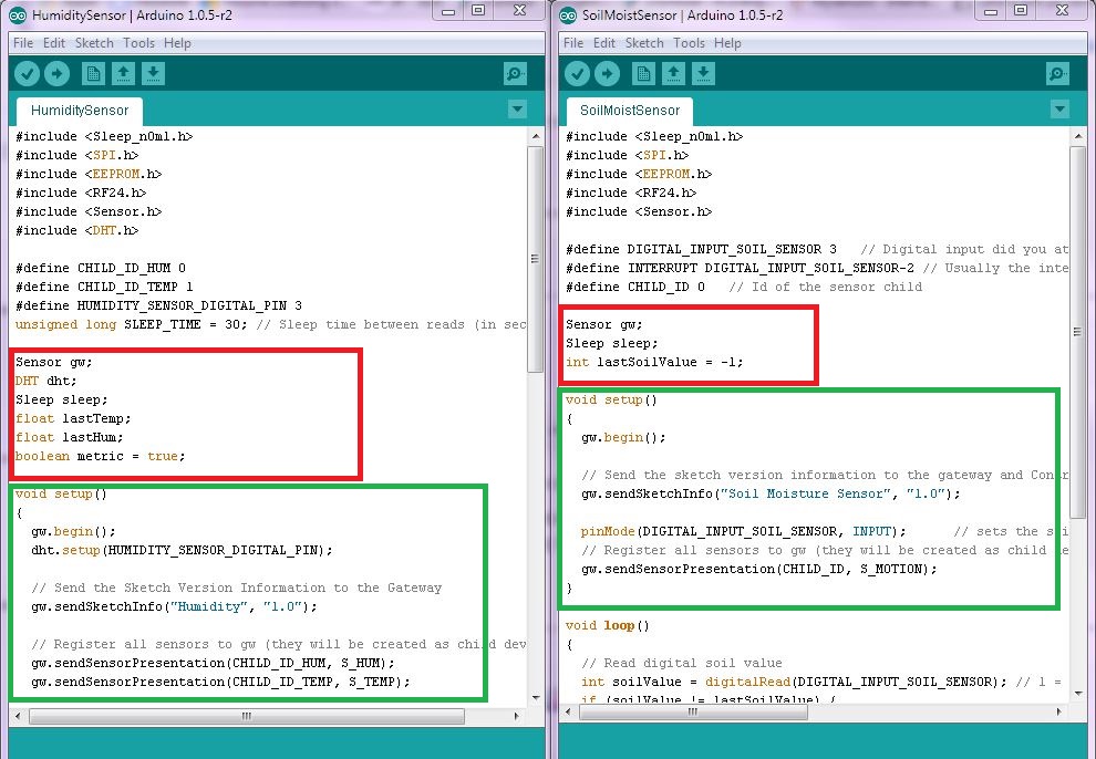
The child ID may also needed to be changed so that there isn't a conflict.Keep copy/paste all the way down in the sketch. Make sure that you place the code in the right place.If its inside the void setup() in one code, paste it inside the void setup() in the target code, I marked it green below. As you can see in the attached picture below in the red rectangle, Sensor gw; is in both codes so don't copy that. You only need to copy/paste the parts that are unique!
Just keep trying! If I can do it, I'm sure you can too!
-
Well this is my first attempt of merging some senses the code compiled with no errors, and they recognised by Vera, but I get no readings or activations as if they're dead
    ///#include <Sleep_n0m1.h>
    #include <SPI.h>
    #include <EEPROM.h>
    #include <RF24.h>
    #include <Sensor.h>
    #include <Relay.h>   //andys Added

    #define DIGITAL_INPUT_SENSOR 3   // The digital input you attached your motion sensor.  (Only 2 and 3 generates interrupt!)
    #define INTERRUPT DIGITAL_INPUT_SENSOR-2 // Usually the interrupt = pin -2 (on uno/nano anyway)
    #define CHILD_ID 7   // Id of the sensor child
    #define RELAY_1  4  //andys Added// Arduino Digital I/O pin number for first relay (second on pin+1 etc)
    #define NUMBER_OF_RELAYS 1 //andys Added
    #define RELAY_ON 0  //andys Added
    #define RELAY_OFF 1  //andys Added

    Sensor gw;
    //Sleep sleep;

    void setup()
    {
      EEPROM.write(EEPROM_RELAY_ID_ADDRESS, 0);

      gw.begin();

      // Send the sketch version information to the gateway and Controller
      gw.sendSketchInfo("Motion Sensor", "1.0");
      gw.sendSketchInfo("Relay", "1.0");  //Andy Added

      pinMode(DIGITAL_INPUT_SENSOR, INPUT);      // sets the motion sensor digital pin as input
      // Register all sensors to gw (they will be created as child devices)
      gw.sendSensorPresentation(CHILD_ID, S_MOTION);
      for (int i=0; i<NUMBER_OF_RELAYS;i++) {   //Andy Added
      gw.sendSensorPresentation(RELAY_1+i, S_LIGHT);  //Andy Added

    }
     // Fetch relay status    //Andy Added
      for (int i=0; i<NUMBER_OF_RELAYS;i++) {    //Andy Added
        // Make sure relays are off when starting up   //Andy Added
        digitalWrite(RELAY_1+i, RELAY_OFF);   //Andy Added
        // Then set relay pins in output mode   //Andy Added
        pinMode(RELAY_1+i, OUTPUT);      //Andy Added

        // Request/wait for relay status //Andy Added
        gw.getStatus(RELAY_1+i, V_LIGHT);   //Andy Added
        setRelayStatus(gw.getMessage()); // Wait here until status message arrive from gw
      }  //Andy Added


     }

    void loop()
    {
        if (gw.messageAvailable()) {   //Andy Added
        message_s message = gw.getMessage();   //Andy Added
        setRelayStatus(message);   //Andy Added
      // Read digital motion value
      boolean tripped = digitalRead(DIGITAL_INPUT_SENSOR) == HIGH;

      Serial.println(tripped);
      gw.sendVariable(CHILD_ID, V_TRIPPED, tripped?"1":"0");  // Send tripped value to gw

      // Power down the radio.  Note that the radio will get powered back up
      // on the next write() call.
      delay(200); //delay to allow serial to fully print before sleep
     // gw.powerDown();
    //  sleep.pwrDownMode(); //set sleep mode
    //  sleep.sleepInterrupt(INTERRUPT,CHANGE);
    }

    }

    void setRelayStatus(message_s message) {
      if (message.header.messageType==M_SET_VARIABLE &&
          message.header.type==V_LIGHT) {
         int incomingRelayStatus = atoi(message.data);
         // Change relay state
         digitalWrite(message.header.childId, incomingRelayStatus==1?RELAY_ON:RELAY_OFF);
         // Write some debug info
         Serial.print("Incoming change for relay on pin:");
         Serial.print(message.header.childId);
         Serial.print(", New status: ");
         Serial.println(incomingRelayStatus);
       }
    }
I think I've overlooked something in order not for this to work
-
Why not a default "multisensor" on the mysensors site at the example page? I see a lot of people like me who are new to arduino and looking for a multisensor sketch. For me the ultimate sensor is like the "roomnode" like a jeenode : Motion + light (LDR) + temp (ds18b20), where motion message is direct and the others once a minute or so.
-
:)
Perhaps we can get a list of preferred combinations and I can work on that alongside anyone else who may wish to do that too.
I'd like to help but also would like it 100% debugged before we publish.
-
A common multi-sensors-combination is:
Motion + Light (LDR or Photo resistor) + DHT (Temp+Humidity)
I would prefer if the example sleeps Arduino+radio while doing nothing.
-
@marceltrapman I'll second that :) I'm working on combining the Light-DHT but I'd really like to get the complete set going.
-
What would be interesting is to make the multi-sensor sketch so that if we ran it either powered or on battery it would adjust its behaviour accordingly. Something like the AEON 4-in-1.
When you are on battery, it is all about conserving that power source, and while on mains, it is all about consistency of data updates and possibly adding other functionality.
Plus, I wanted to work on that LED idea so that we can broadcast a 'message' to a grouping of sensors and activate an (RGB) LED in the sensor.
Too much?
@BulldogLowell Good idea. Dunno if it is possible to recognise if it is battery powered or not.
But this is the way to go imho.
I think it is not a question of 'too much' but more 'is this even possible'? -
A common multi-sensors-combination is:
Motion + Light (LDR or Photo resistor) + DHT (Temp+Humidity)
I would prefer if the example sleeps Arduino+radio while doing nothing.
-
I merged the Temp/Humidity and Light sensor functions into already included sensor on Vera. Apparently the Gateway will not recognize such a change made inline. The Serial Monitor showed the Light value being reported but it was never displayed on Vera. I tried running the Inclusion function but it never showed the Light sensor in the Node.
Knowing the way Vera works, this doesn't really surprise me all that much. I'm guessing that in order to make this work one has to ClearEEPROM on the Sensor, remove the Node from Vera, upload the revised sketch to the Sensor and go through the Inclusion again, essentially starting from scratch.
Re: This posting about merging sensors.
I did exactly as I said in there:
- Removed the Node and Children from Vera. At this point I have only the MySensors Plugin visible in Vera
- Cleared EEPROM on the Sensor
- Uploaded the new sketch to the Sensor
- Ran Inclusion on Vera
When inclusion ran it found 4 new devices (I assume Node, Temp, Hum, Light)
But Vera does NOT display the new devices even after multiple restarts. The Serial Monitor on the Sensor shows that it is indeed sending data and receiving ACK OK from the Gateway. Subsequent attempts at Inclusion do not find any devices so the GW at least knows they are there.
Looking at the SysLog there is no sensor data being reported since I started this so apparently it isn't getting through.
I'm going to Clear EEPROM again and fallback to the Temp/Hum sensor in case there is a problem with the new sensor code.
Well, that's interesting. After reverting to he 2 sensor node Inclusion found 3 new devices and Vera now displays them. Yet when the 3 sensor code was running the serial monitor showed transmission and ACK for all three sensors. Now I'm confused.
[UPDATE]
I sorted it out, i had several problems.- It appears the it is necessary to RESET the Node prior to Inclusion. Vera will then find the devices and display them. Absent the Reset it looks like Vera found them but that was all.
- When it finally displayed the LIGHT, it was showing as an ON/OFF Switch not a level. In the Setup routine i had
gw.sendSensorPresentation(CHILD_ID_LIGHT, S_LIGHT);
rather than
gw.sendSensorPresentation(CHILD_ID_LIGHT, S_LIGHT_LEVEL);
and similarly in the sending of the data I had left off the "_LEVEL" not realizing that that told the GW how to display the device. Now I know :)
Anyway, the three input sensor is working. In the process of making the conversion I changed the Light Level to a floating number for consistency on the display .I've also implemented a simple Keepalive; every "N" times through the loop it resends the last temperature reading. i have this set to 30 times (and I adjusted the basic data cycle from 30 seconds to 60 seconds) so the keep alive occurs every 30 minutes whether the sensor sends any data in that time or not.
Hello! It looks like you're interested in this conversation, but you don't have an account yet.
Getting fed up of having to scroll through the same posts each visit? When you register for an account, you'll always come back to exactly where you were before, and choose to be notified of new replies (either via email, or push notification). You'll also be able to save bookmarks and upvote posts to show your appreciation to other community members.
With your input, this post could be even better 💗
Register Login