implementing multiple sensors
-
:)
Perhaps we can get a list of preferred combinations and I can work on that alongside anyone else who may wish to do that too.
I'd like to help but also would like it 100% debugged before we publish.
-
A common multi-sensors-combination is:
Motion + Light (LDR or Photo resistor) + DHT (Temp+Humidity)
I would prefer if the example sleeps Arduino+radio while doing nothing.
-
@marceltrapman I'll second that :) I'm working on combining the Light-DHT but I'd really like to get the complete set going.
-
What would be interesting is to make the multi-sensor sketch so that if we ran it either powered or on battery it would adjust its behaviour accordingly. Something like the AEON 4-in-1.
When you are on battery, it is all about conserving that power source, and while on mains, it is all about consistency of data updates and possibly adding other functionality.
Plus, I wanted to work on that LED idea so that we can broadcast a 'message' to a grouping of sensors and activate an (RGB) LED in the sensor.
Too much?
@BulldogLowell Good idea. Dunno if it is possible to recognise if it is battery powered or not.
But this is the way to go imho.
I think it is not a question of 'too much' but more 'is this even possible'? -
A common multi-sensors-combination is:
Motion + Light (LDR or Photo resistor) + DHT (Temp+Humidity)
I would prefer if the example sleeps Arduino+radio while doing nothing.
-
I merged the Temp/Humidity and Light sensor functions into already included sensor on Vera. Apparently the Gateway will not recognize such a change made inline. The Serial Monitor showed the Light value being reported but it was never displayed on Vera. I tried running the Inclusion function but it never showed the Light sensor in the Node.
Knowing the way Vera works, this doesn't really surprise me all that much. I'm guessing that in order to make this work one has to ClearEEPROM on the Sensor, remove the Node from Vera, upload the revised sketch to the Sensor and go through the Inclusion again, essentially starting from scratch.
Re: This posting about merging sensors.
I did exactly as I said in there:
- Removed the Node and Children from Vera. At this point I have only the MySensors Plugin visible in Vera
- Cleared EEPROM on the Sensor
- Uploaded the new sketch to the Sensor
- Ran Inclusion on Vera
When inclusion ran it found 4 new devices (I assume Node, Temp, Hum, Light)
But Vera does NOT display the new devices even after multiple restarts. The Serial Monitor on the Sensor shows that it is indeed sending data and receiving ACK OK from the Gateway. Subsequent attempts at Inclusion do not find any devices so the GW at least knows they are there.
Looking at the SysLog there is no sensor data being reported since I started this so apparently it isn't getting through.
I'm going to Clear EEPROM again and fallback to the Temp/Hum sensor in case there is a problem with the new sensor code.
Well, that's interesting. After reverting to he 2 sensor node Inclusion found 3 new devices and Vera now displays them. Yet when the 3 sensor code was running the serial monitor showed transmission and ACK for all three sensors. Now I'm confused.
[UPDATE]
I sorted it out, i had several problems.- It appears the it is necessary to RESET the Node prior to Inclusion. Vera will then find the devices and display them. Absent the Reset it looks like Vera found them but that was all.
- When it finally displayed the LIGHT, it was showing as an ON/OFF Switch not a level. In the Setup routine i had
gw.sendSensorPresentation(CHILD_ID_LIGHT, S_LIGHT);
rather than
gw.sendSensorPresentation(CHILD_ID_LIGHT, S_LIGHT_LEVEL);
and similarly in the sending of the data I had left off the "_LEVEL" not realizing that that told the GW how to display the device. Now I know :)
Anyway, the three input sensor is working. In the process of making the conversion I changed the Light Level to a floating number for consistency on the display .I've also implemented a simple Keepalive; every "N" times through the loop it resends the last temperature reading. i have this set to 30 times (and I adjusted the basic data cycle from 30 seconds to 60 seconds) so the keep alive occurs every 30 minutes whether the sensor sends any data in that time or not.
-
I have been working on one that combines a servo, temperature and light sensor. I have had it running for a while now. I have been busy lately and have not really had time to write it up and post it. I am attaching what I have, maybe it would help or give some ideas.
[Servo-Light-Temp-Sensors.zip](uploading 100%) -
Probably not the easiest to look at since it combined a RGB diode and RFID reader. But it works very well.
https://github.com/wbcode/ham/blob/master/arduino/MySensorRFIDandRGB/RGBandRFID/RGBandRFID.inoI should add that I don't use the Vera as a controler.
WB
-
I have been working on one that combines a servo, temperature and light sensor. I have had it running for a while now. I have been busy lately and have not really had time to write it up and post it. I am attaching what I have, maybe it would help or give some ideas.
[Servo-Light-Temp-Sensors.zip](uploading 100%).zip did not take here are the files
-
If i was a programmer... i would write a wizard app/script/webpage that would ask a user a bunch of questions..
- What Arduino are they using.
- what sensors/actuators they want to have on their sketch
- what pins ( showing those available) are they going to connect the sensor to.
- What they want to call the sketch
- Relay mode?
- Sampling times
etc etc
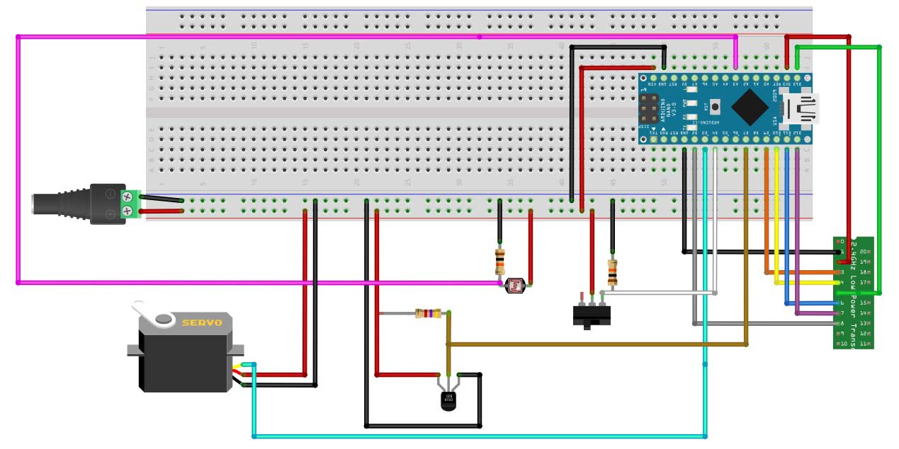
if i was a really good programmer, i would produce a schematic/frizing like above ;-)
Unfortunately in not a programmer..really wish i was, and am trying to get there slowly...so if you guys are cool with waiting another 5 years ill get something together...
-
We've actually thought about doing a sketch-generator also. It's down there on the list. And it would be a web-thing (hopefully with OTA update) :)
-
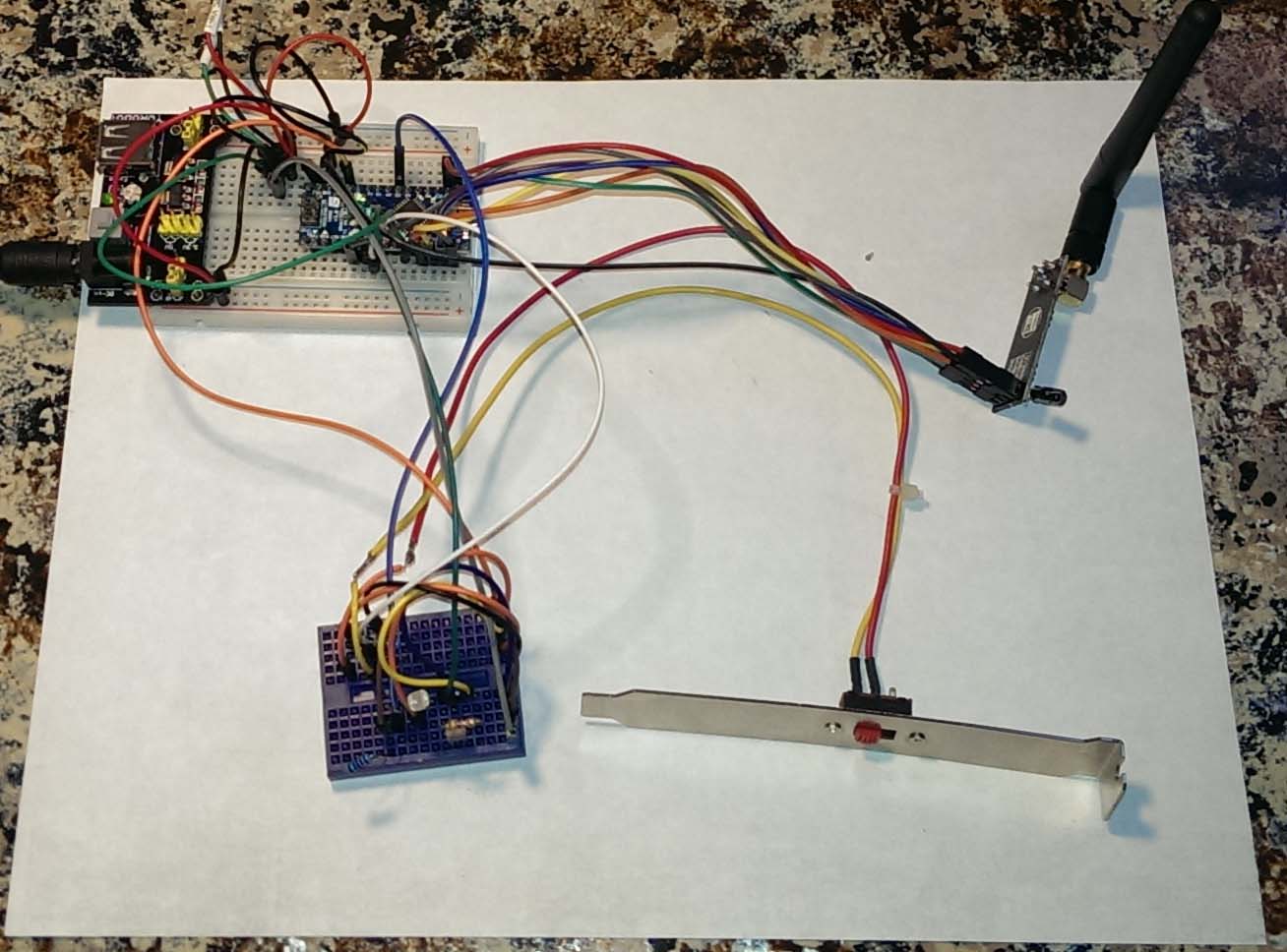
A few people have asked about the hardware I used.
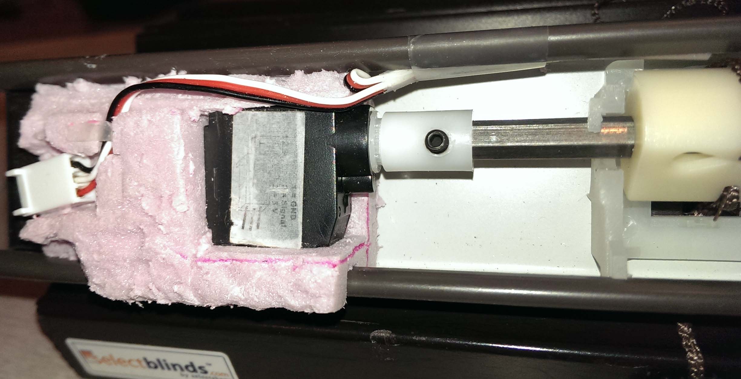
A quick write up on what hardware I used for the blinds-light-temp-servo project.
My binds are 1” not the 2” that you see in the projects listed in the forums. The standard servos will not fit inside the 1” blinds, so I had to use the mini servos. My concern was that the mini servos would not have the torque necessary to operate the tilt mechanism. But for at least the 45x38 blinds I have the mini servo worked great, not sure about larger size blinds.
I removed the tilt wand and mechanism completely and connected the servo directly to the hex rod. I used a piece of 2” foam insulation and cut out a cavity for the servo and used it as the mounting bracket.
I purchased a Nano IO shield from imall.iteadstudio.com, which I plan to use when I assemble the parts into a final enclosure and mount it inside the cabinet. With the Light and Temp sensors mounted inside the window frame.
I use PLEG to control the blinds.
Parts used:
http://www.ebay.com/itm/291084936296?ssPageName=STRK:MEWAX:IT&_trksid=p3984.m1423.l2649 – used to connect the servo to the hex rod. Note I had to cut off some of the hex rod so the servo would sit inside the head rail.
I tried to upload a 5 second video of the binds in operation, but the file is too large.

Hello! It looks like you're interested in this conversation, but you don't have an account yet.
Getting fed up of having to scroll through the same posts each visit? When you register for an account, you'll always come back to exactly where you were before, and choose to be notified of new replies (either via email, or push notification). You'll also be able to save bookmarks and upvote posts to show your appreciation to other community members.
With your input, this post could be even better 💗
Register Login