CNC PCB milling
-
Best way to get rid of the dust seems to be not making dust to start with.
Enjoy!
https://youtu.be/PpXG1X9yoxs@executivul Which car shampoo?
How well does it work? Would it work better if you flooded it a bit more so that it was sitting, say, a couple mm under shampoo solution?
-
I suppose your etching bit might last longer too, since maybe the liquid would help cool it.
-
Unfortunately I can not disclose this secret recipe, all I can tell you is that s some cationic surfactant mixed with some dihydrogen peroxide :sunglasses:
To be honest I don't know the brand, I've first tried liquid soap undiluted but was to thick and was gathering around the bit like a small tornado and splashing everywhere, decided to add some water and went looking for a spray bottle, found one with some handwriting "car shampoo", it is thicker than plain water, but not as thick as liquid soap, so it might be diluted, I still have some for a few more boards then I'll go by trial and error with dish/hand/car wash and water.
So much better not to have windows open at 0C(32F) and the vacuum howling. Only the 2.0mm endmill still creates dust, normal engraving and drilling do not.
Don't forget to mill on acrylic/plastic as mdf will swell if wet. -
Looks like my CNC2418 is on track to be delivered this Monday. It has already cleared customs.
So, since it will be arriving well ahead of all the various bits and such, I'm guessing that just a few etching bits will be enough to get me started and confirm whether my machine can route 6 mil isolation.
The kit itself includes 0.1mm bits (Diameter: 3.175mm tip: 0.1mm length: 30mm).
-
-
@andrew said in CNC PCB milling:
@neverdie so, I expect your first boards tomorrow :)
But wait, I'm still waiting for the magic numbers from you. :) Otherwise, I'll be all dressed with nowhere to go.
-
@andrew said in CNC PCB milling:
@neverdie so, I expect your first boards tomorrow :)
But wait, I'm still waiting for the magic numbers from you. :) Otherwise, I'll be all dressed with nowhere to go.
@neverdie once the assembly is done, you should adjust the stepper drivers' current limiting as well.
it is pololu a4988, you can find the corresponding details here:
https://www.pololu.com/product/1182then, it is always good idea to have the basic settings exported from the board, just in case... you can do it by "$$" command sent from the g code sender gui or directly from the serial terminal.
currently I use the following settings, the machine might be able to create nice results with higher feed rates, but I did not have enough time to test it and I sticked to the current working config.
isolation routing with 2001 bits:
- z cut: -0.05mm
- feed rate: 200
you can calculate the V carving bit's tool width for the given milling depth with the following formula:
tan(bit angle/2) * milling depth * 2 + bit's end width
for excel formula the bit angle should be provided in radians, so it should look like this
tan(radians(bit angle/2)) * milling depth * 2 + bit's end widthedge cut or hole milling with the 0.8mm endmill:
- feed rate: 170
- z cut: -1.7mm
- multi depth, depth/pass: 0.2mm
drilling:
- feed rate: 130
- z cut: -1.8
the spindle should be 1000 everywhere.
most probably your board will not have a bootloader, so it will not be possible to update the firmware via usb serial connection (with avrdude), but it is worth to try it. for me it did not work, so I traced back the MCU pins to the pin rows and used ISP to upgrade the firmware to grbl v1.1f (the board will come with 0.9j if I remember correctly). do not forget to export the gerber settings before you upgrade the firmware, as it will loose those, and you have to re-assign the given values again, after the update.
the ISP pinout (from the pin row's top left corner):
Reset -> pin 2
SCK -> pin 3
MISO -> pin 12
MOSI -> pin 135v -> pin1
gnd-> bottom row(!) e.g. pin 1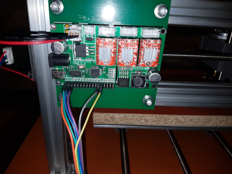
-
The assembly instructions came as a file on a mini CD. Attached for anyone who is interested.
[0_1513463653125_2418-Assembly instructions - English.doc](Uploading 100%)
Hmmm.. I guess the forum only lets me upload photos. Sorry. -
I thought that the ER11 would come pre-installed ("shrink fit" onto the spindle), but it arrived as a separate piece and apparently I'm supposed to attach it by hand. That would seem to be a discrepancy with Jack's store advertises for this device, but, oh well.
Also, I was a bit surprised to see that most, and maybe all, of the plastic parts were 3D printed.
-
@neverdie once the assembly is done, you should adjust the stepper drivers' current limiting as well.
it is pololu a4988, you can find the corresponding details here:
https://www.pololu.com/product/1182then, it is always good idea to have the basic settings exported from the board, just in case... you can do it by "$$" command sent from the g code sender gui or directly from the serial terminal.
currently I use the following settings, the machine might be able to create nice results with higher feed rates, but I did not have enough time to test it and I sticked to the current working config.
isolation routing with 2001 bits:
- z cut: -0.05mm
- feed rate: 200
you can calculate the V carving bit's tool width for the given milling depth with the following formula:
tan(bit angle/2) * milling depth * 2 + bit's end width
for excel formula the bit angle should be provided in radians, so it should look like this
tan(radians(bit angle/2)) * milling depth * 2 + bit's end widthedge cut or hole milling with the 0.8mm endmill:
- feed rate: 170
- z cut: -1.7mm
- multi depth, depth/pass: 0.2mm
drilling:
- feed rate: 130
- z cut: -1.8
the spindle should be 1000 everywhere.
most probably your board will not have a bootloader, so it will not be possible to update the firmware via usb serial connection (with avrdude), but it is worth to try it. for me it did not work, so I traced back the MCU pins to the pin rows and used ISP to upgrade the firmware to grbl v1.1f (the board will come with 0.9j if I remember correctly). do not forget to export the gerber settings before you upgrade the firmware, as it will loose those, and you have to re-assign the given values again, after the update.
the ISP pinout (from the pin row's top left corner):
Reset -> pin 2
SCK -> pin 3
MISO -> pin 12
MOSI -> pin 135v -> pin1
gnd-> bottom row(!) e.g. pin 1@andrew said in CNC PCB milling:
do not forget to export the gerber settings before you upgrade the firmware, as it will loose those, and you have to re-assign the given values again, after the update.
Where are the gerber settings, and how do I export them? Are they in EEPROM, so I just do a complete copy of that? Or does the $$ handle it?
-
I finished putting together the first frame. It was a bit frustrating, because the T-slot nuts they use can come out of the groove, and so to prevent that I had to keep constant tension on it while I tightened it down. I do think most of the T-slot nuts should have been the kind that don't slip out that way.
-
@andrew said in CNC PCB milling:
do not forget to export the gerber settings before you upgrade the firmware, as it will loose those, and you have to re-assign the given values again, after the update.
Where are the gerber settings, and how do I export them? Are they in EEPROM, so I just do a complete copy of that? Or does the $$ handle it?
@NeverDie
firmware settings: it is stored in the EEPROM, but nothing guarantees that the same location will be used for the same parameters in case of different versions, so the output of "$$" command should be saved, this contains everything which you can manually set up if necessary.ER11: take extra care during the installation process to not "harm" the motor's axis. usually the ER11 is pretty tight and howtos mention that the motor should be cooled (by the freezer) and the ER11 should be warmed up before putting them together, to help the mounting process and to prevent unwanted distortion.
I put the CNC 2418 assembly guide to my share, for ones it is interesting.
-
@neverdie once the assembly is done, you should adjust the stepper drivers' current limiting as well.
it is pololu a4988, you can find the corresponding details here:
https://www.pololu.com/product/1182then, it is always good idea to have the basic settings exported from the board, just in case... you can do it by "$$" command sent from the g code sender gui or directly from the serial terminal.
currently I use the following settings, the machine might be able to create nice results with higher feed rates, but I did not have enough time to test it and I sticked to the current working config.
isolation routing with 2001 bits:
- z cut: -0.05mm
- feed rate: 200
you can calculate the V carving bit's tool width for the given milling depth with the following formula:
tan(bit angle/2) * milling depth * 2 + bit's end width
for excel formula the bit angle should be provided in radians, so it should look like this
tan(radians(bit angle/2)) * milling depth * 2 + bit's end widthedge cut or hole milling with the 0.8mm endmill:
- feed rate: 170
- z cut: -1.7mm
- multi depth, depth/pass: 0.2mm
drilling:
- feed rate: 130
- z cut: -1.8
the spindle should be 1000 everywhere.
most probably your board will not have a bootloader, so it will not be possible to update the firmware via usb serial connection (with avrdude), but it is worth to try it. for me it did not work, so I traced back the MCU pins to the pin rows and used ISP to upgrade the firmware to grbl v1.1f (the board will come with 0.9j if I remember correctly). do not forget to export the gerber settings before you upgrade the firmware, as it will loose those, and you have to re-assign the given values again, after the update.
the ISP pinout (from the pin row's top left corner):
Reset -> pin 2
SCK -> pin 3
MISO -> pin 12
MOSI -> pin 135v -> pin1
gnd-> bottom row(!) e.g. pin 1 -
@rmtucker it is not 1000rpm, but the pwm control for the whole spindle speed range. see the details in the official document.
once you use the spindle speed with the value of $30 or above, then the controller will drive the spindle with continuous voltage, without pwm, so it will use its maximum rpm.
compared to bigger cncs with bigger spindles (e.g. what you can see from @executivul's video above) , 2418's is not that fast (in rpm), on the other hand it should not be "very slow". can you show a video on that? -
@NeverDie
firmware settings: it is stored in the EEPROM, but nothing guarantees that the same location will be used for the same parameters in case of different versions, so the output of "$$" command should be saved, this contains everything which you can manually set up if necessary.ER11: take extra care during the installation process to not "harm" the motor's axis. usually the ER11 is pretty tight and howtos mention that the motor should be cooled (by the freezer) and the ER11 should be warmed up before putting them together, to help the mounting process and to prevent unwanted distortion.
I put the CNC 2418 assembly guide to my share, for ones it is interesting.
@andrew said in CNC PCB milling:
I put the CNC 2418 assembly guide to my share, for ones it is interesting.
Yes, those are exactly the same instructions I received with my kit too.
-
@NeverDie
firmware settings: it is stored in the EEPROM, but nothing guarantees that the same location will be used for the same parameters in case of different versions, so the output of "$$" command should be saved, this contains everything which you can manually set up if necessary.ER11: take extra care during the installation process to not "harm" the motor's axis. usually the ER11 is pretty tight and howtos mention that the motor should be cooled (by the freezer) and the ER11 should be warmed up before putting them together, to help the mounting process and to prevent unwanted distortion.
I put the CNC 2418 assembly guide to my share, for ones it is interesting.
@andrew
I tried connecting to the Woodpecker board using the Arduino serial terminal at 115200 baud. It greets me by saying:Grbl 0.9j ['$' for help]However, if I send it $ I get no response. If I send it $$, I get no response either.
Is this normal?
How do I send it $$ and get it to respond?
-
@andrew
I tried connecting to the Woodpecker board using the Arduino serial terminal at 115200 baud. It greets me by saying:Grbl 0.9j ['$' for help]However, if I send it $ I get no response. If I send it $$, I get no response either.
Is this normal?
How do I send it $$ and get it to respond?
Hello! It looks like you're interested in this conversation, but you don't have an account yet.
Getting fed up of having to scroll through the same posts each visit? When you register for an account, you'll always come back to exactly where you were before, and choose to be notified of new replies (either via email, or push notification). You'll also be able to save bookmarks and upvote posts to show your appreciation to other community members.
With your input, this post could be even better 💗
Register Login