
Philips LivingColors MySensor node
-
I had a Philips LivingColors Generation 1 light lying around at home and by chance and I stumbled upon Ivo Knutsel's instructions on how to control the LivingColors using an Arduino here : http://www.knutsel.org/tag/livingcolors/

So I thought that this will be a good start for me to mess with the MySensors !
I tested some controllers and I decided to go for the Domoticz controller with a MySensors Ethernet Gateway.
Domoticz works just fine with my MySensors, it also works with my Philips Hue lamps, it allows me to display a drawing of my apartment and is open source; perfect !After some fiddling around and building other small MySensors (relays, LED-strip controllers, replacing our alarm system, etc) I finally came up with the following solution to control my LivingColors lamp.
Below s the information on what I came up with to control a LivingColors lamp using a MySensor node :-
First : All credits goes to Ivo Knutsel for all his hard work ! Please have a look at his webpage because it contains all the details on how the connection and detection of the lamp works.
-
Second : This only works for a Philips LivingColors Generation 1 lamp.
To make it easier to connect the CC2500 antenna to the Arduino I decided for a Arduino Pro Mini 3.3V. This avoids one of the 74LVC125A-circuits (which for me was a nightmare to solder !).
The schematic :
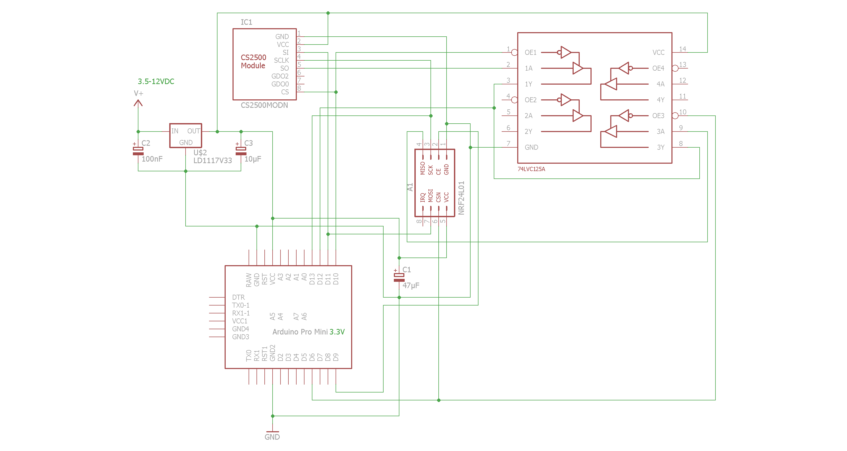
And the components mounted on a small board :
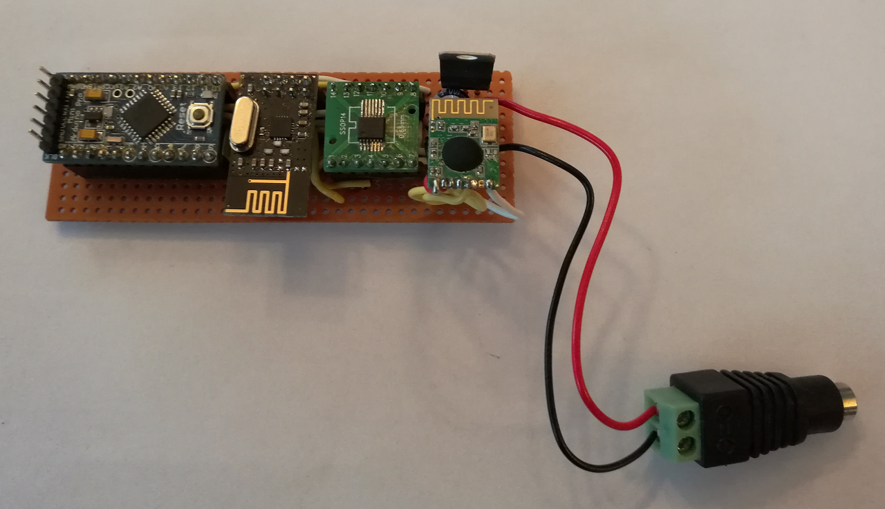
BOM:
- NRF24L01+
- Arduino Pro Mini 3.3V
- CS2500
- 74LVC125A
- 47µF capacitor
- 10 µF capacitor
- 100nF capacitor
- LD33V voltage regulator
Finally the sketch :
/*
  MTLivingColors --- Link a gen 1 Philips LivingColors lamp with MySensors.
    Author : Mathias Thorell.
-----------------------------------------------------------------------------

  This would never have been possible without the efforts of the following people :
   Ivo Knutsel   : The investigations, schematic and source code to interact with the Living Light : http://www.knutsel.org/tag/livingcolors/
   Henrik Ekblad : Founder of MySensors : www.mysensors.org
   darkoman      : Class for fading from one RGB to another RGB color : http://www.codeproject.com/Articles/13497/An-advanced-gradient-rendering-class
   johnwasser    : The Fire effect : http://forum.arduino.cc/index.php?topic=135206.msg1016852#msg1016852
   Google        : For everything else...

   2016-02-27 First working version.
   2016-02-28 Tested to adda DHT221 sensor, just for fun. Removed.
   2016-02-29 Added fading. First realese candidate.
   2016-03-01 Added Fire- and Aurora effects.
   2016-03-08 Added Water-effect (requested by my daughter Angelina).
   2016-08-05 Cleaned up and removed all non-LivingColors stuff.
   2016-08-23 Removed effects to keep theis example as clean as possible.

 Note : Make sure to undef the SOFTSPI-constant in MyConfig.h, otherwise the two radios on the SPI bus
        will not cooperate at all.

 Known issues :
        Lamp flickers while fading.

 ToDo : Fix flickering while fading.
        Add possibility to find lamp address/id. Perhaps use an I/O-pin to enter learning mode ?
        Enable handling of more than only one lamp.
        Test: Should we become a S_RGBW instead of a S_RGB lamp ?
        Shall we or shall we not handle the V_PERCENT message ?
        Store Lamp Id in program memory ?
*/
//----------------------------------------------------------------------------------
#include <MyConfig.h>
#include <MyHw.h>
#include <MyHwATMega328.h>
#include <MyMessage.h>
#include <MyParser.h>
#include <MyParserSerial.h>
#include <MySensor.h>
#include <MySigning.h>
#include <MySigningNone.h>
#include <MyTransport.h>
#include <MyTransportNRF24.h>
#include <Version.h>

#include <DigitalIO.h>
#include <DigitalPin.h>
#include <I2cConstants.h>
#include <PinIO.h>
#include <SoftI2cMaster.h>
#include <SoftSPI.h>

#include <CC2500.h>
#include <ColourConversion.h>
#include <LivingColors.h>
#include <SPI.h>
//----------------------------------------------------------------------------------
// NRF24 pins for MySensors :
#define RF24_CE_PIN       9 // Default value
#define RF24_CS_PIN       6 // Default is 10, but we must use 6 since 10 is used by the CC2500

// CC2250 pins (sharing MISO, MOSI and SCK with the NRF24)
#define lcMOSI   11    // SPI master data out pin
#define lcMISO   12    // SPI master data in pin
#define lcSCK    13    // SPI clock pin
#define lcCS     10    // SPI slave select pin 10

#define node       1 // Assigning the node Id (this will be the address for controller)
#define TheLampNum 1 // Sensor number needed in the custom devices set up

#define StateOff    0
#define StateOn     1
//----------------------------------------------------------------------------------
// Helper class :
class RGBColor
{
  private:
    int FRed,
        FGreen,
        FBlue;
  public:
    RGBColor (int Red,int Green,int Blue) :
        FRed(Red),
        FGreen(Green),
        FBlue(Blue)
    {
    }
    RGBColor(void) { FRed = 0; FGreen = 0; FBlue = 0; }
    RGBColor(const RGBColor &From) { FRed = From.Red(); FGreen = From.Green(); FBlue = From.Blue(); }

    void Set(int red,int green,int blue)  { FRed = red; FGreen = green; FBlue = blue; }
    void Set(RGBColor From) { FRed = From.Red(); FGreen = From.Green(); FBlue = From.Blue(); }
    int Red()   const { return (FRed);   }
    int Green() const { return (FGreen); }
    int Blue()  const { return (FBlue);  }
};
//----------------------------------------------------------------------------------
// Class to fade from one RGB set to another RGB set
class Fader
{
  private:
    LivingColors *FLivCol;

  public:
    // Thanks to darkoman
    /* Construct the fader for the pins to manipulate.
     * Make sure these are pins that support Pulse
     * width modulation (PWM), these are the digital pins
     * denoted with a tilde(~) common are ~3, ~5, ~6, ~9, ~10
     * and ~11 but check this on your type of arduino.
     */
    Fader(LivingColors *livCol)
    {
      FLivCol = livCol;
    }

    // Fade from in to out
    void fade(const   RGBColor &in,
              const   RGBColor &out,
              unsigned n_steps = 256,  //default take 256 steps
              unsigned timeMS  = 2)   //wait 10 ms per step
    {
      // Based on work by Darkoman; http://www.codeproject.com/Articles/13497/An-advanced-gradient-rendering-class
      double percent;
      int red,green,blue;
      for (int i = 0;i < 100;i++)
      {
        percent = 1.0 - ((double)i / (double)100);
        red   = (int)((double)in.Red()   * percent) + (int)(out.Red()   * (1.0 - percent));
        green = (int)((double)in.Green() * percent) + (int)(out.Green() * (1.0 - percent));
        blue  = (int)((double)in.Blue()  * percent) + (int)(out.Blue()  * (1.0 - percent));

        red   = red   < 0 ? 0 : red;
        green = green < 0 ? 0 : green;
        blue  = blue  < 0 ? 0 : blue;

        red   = red   > 255 ? 255 : red;
        green = green > 255 ? 255 : green;
        blue  = blue  > 255 ? 255 : blue;

        // Write the new color output :
        FLivCol->turnLampOnRGB(0,red,green,blue);

        delay(timeMS);
      }
    }
};
//----------------------------------------------------------------------------------
// NRF24
MyTransportNRF24 transport(RF24_CE_PIN,RF24_CS_PIN,RF24_PA_LEVEL_GW);

// Hardware profile
MyHwATMega328 hw;

// Main sensor class :
MySensor su;

// Main control class to handle LivingColors :
LivingColors livcol(lcCS,lcSCK,lcMOSI,lcMISO);
RGBColor CurrentRGB,LastRGB;

MyMessage livMsg(TheLampNum,V_RGB);
//----------------------------------------------------------------------------------
// Lamp address(es) :
// This is the address of my Living Colors lamp.
// To find your unique id see reference to sketch below at the call to livcol.addLamp().
unsigned char lamp1[9] = { 0x00, 0xC7, 0x87, 0x66, 0xB7, 0x1A, 0xFF, 0x8A, 0x11 }; // Lamp address

// Last known state; On (1) or Off (0)
int LastState;

// Instance of our fader class :
Fader TheFader(&livcol);
//----------------------------------------------------------------------------------
void setup()
{
  // setup serial port
  Serial.begin(115200);

  // Initialize library and add callback for incoming messages
  su.begin(DoIncomingMessage,node,true);

  // Send the sketch version information to the gateway and Controller
  su.sendSketchInfo("RGB Node","1.1");

  // Register the sensor to gw
  su.present(TheLampNum,S_RGB_LIGHT,"LivingColors");

  // Load last known states of our lamp :
  LastState = su.loadState(0); // Last lamp state
  LastRGB.Set(su.loadState(1),su.loadState(2),su.loadState(3));

  // Initialize or lamp :
  livcol.init();
  livcol.clearLamps();
  livcol.addLamp(lamp1); // Add our lamp. Lamp address/id must be taken from Ivo's original sketch from here :
                         // http://www.knutsel.org/2010/04/11/using-the-cc2500-arduino-shield/
  if (LastState)
  {
    // Turn on lamp is it was on before :
    livcol.turnLampOnRGB(0,LastRGB.Red(),LastRGB.Green(),LastRGB.Blue());
  }
  else
  {
    // Turn off lamp is it was off before :
    livcol.turnLampOff(0);
  }
}
//----------------------------------------------------------------------------------
void loop()
{
  // Do the MySensors dance :
  su.process();
}
//----------------------------------------------------------------------------------
// Parse MySensors messages :
void DoIncomingMessage(const MyMessage &message)
{
  if (message.type == V_LIGHT)
  {
     if (message.getBool())
     {
Serial.println("Lamp On");
       if (LastState == StateOff)
       {
         RGBColor fromRGB(0,0,0);
         RGBColor toRGB(LastRGB);
         TheFader.fade(fromRGB,toRGB);
       }
       livcol.turnLampOnRGB(0,LastRGB.Red(),LastRGB.Green(),LastRGB.Blue());
       LastState = su.loadState(0);
     }
     else
     {
Serial.println("Lamp Off");
       if (LastState >= StateOn)
       {
         RGBColor fromRGB(LastRGB);
         RGBColor toRGB(0,0,0);
         TheFader.fade(fromRGB,toRGB);
       }
       livcol.turnLampOff(0);

       LastState = StateOff;
     }
     // Store state in eeprom
     su.saveState(0,LastState);
  }
  else if (message.type == V_RGB)
  {
    // starting to process the hex code
    String hexstring = message.getString(); // Here goes the hex color code coming from controller through MySensors (ex: FF9A00)
    long   number = (long) strtol(&hexstring[0],NULL,16);
    CurrentRGB.Set((number >> 16) & 0xFF,(number >> 8) & 0xFF,number & 0xFF);

    // Write some debug info
Serial.print("Red is " );
Serial.println(CurrentRGB.Red());
Serial.print("Green is " );
Serial.println(CurrentRGB.Green());
Serial.print("Blue is " );
Serial.println(CurrentRGB.Blue());

    TheFader.fade(LastRGB,CurrentRGB);
    livcol.turnLampOnRGB(0,CurrentRGB.Red(),CurrentRGB.Green(),CurrentRGB.Blue());
    LastRGB.Set(CurrentRGB);
    LastState = StateOn;
    su.saveState(0,LastState);
    su.saveState(1,LastRGB.Red());
    su.saveState(2,LastRGB.Green());
    su.saveState(3,LastRGB.Blue());
  }
  else if (message.type == V_PERCENTAGE)
  {
    //Todo/missing: We need to consider this dimmer value when setting RGB's.
    String percstring = message.getString(); // 0-100 %
    long   number = (long) strtol(&percstring[0],NULL,10);
Serial.print("Dim value=");
Serial.println(number);
    double dRed   = (double)CurrentRGB.Red()   * ((double)number / 100.0);
    double dGreen = (double)CurrentRGB.Green() * ((double)number / 100.0);
    double dBlue  = (double)CurrentRGB.Blue()  * ((double)number / 100.0);

    // Nope, tested and we don't need this. Taken care of via RGB ?
    // livcol.turnLampOnRGB(0,(int)dRed,(int)dGreen,(int)dBlue);
  }
  else
  {
Serial.print("Unknown MsgType=");
Serial.println(message.type);
  }
}
//----------------------------------------------------------------------------------
(This sketch is the bare minimum to control the LivingColors lamp.
I do possess a more complete sketch which includes some nice light effects too.)Questions and suggestions are welcome !
Enjoy !
/T -
-
I had a Philips LivingColors Generation 1 light lying around at home and by chance and I stumbled upon Ivo Knutsel's instructions on how to control the LivingColors using an Arduino here : http://www.knutsel.org/tag/livingcolors/
So I thought that this will be a good start for me to mess with the MySensors !
I tested some controllers and I decided to go for the Domoticz controller with a MySensors Ethernet Gateway.
Domoticz works just fine with my MySensors, it also works with my Philips Hue lamps, it allows me to display a drawing of my apartment and is open source; perfect !After some fiddling around and building other small MySensors (relays, LED-strip controllers, replacing our alarm system, etc) I finally came up with the following solution to control my LivingColors lamp.
Below s the information on what I came up with to control a LivingColors lamp using a MySensor node :-
First : All credits goes to Ivo Knutsel for all his hard work ! Please have a look at his webpage because it contains all the details on how the connection and detection of the lamp works.
-
Second : This only works for a Philips LivingColors Generation 1 lamp.
To make it easier to connect the CC2500 antenna to the Arduino I decided for a Arduino Pro Mini 3.3V. This avoids one of the 74LVC125A-circuits (which for me was a nightmare to solder !).
The schematic :
And the components mounted on a small board :
BOM:
- NRF24L01+
- Arduino Pro Mini 3.3V
- CS2500
- 74LVC125A
- 47µF capacitor
- 10 µF capacitor
- 100nF capacitor
- LD33V voltage regulator
Finally the sketch :
/*
  MTLivingColors --- Link a gen 1 Philips LivingColors lamp with MySensors.
    Author : Mathias Thorell.
-----------------------------------------------------------------------------

  This would never have been possible without the efforts of the following people :
   Ivo Knutsel   : The investigations, schematic and source code to interact with the Living Light : http://www.knutsel.org/tag/livingcolors/
   Henrik Ekblad : Founder of MySensors : www.mysensors.org
   darkoman      : Class for fading from one RGB to another RGB color : http://www.codeproject.com/Articles/13497/An-advanced-gradient-rendering-class
   johnwasser    : The Fire effect : http://forum.arduino.cc/index.php?topic=135206.msg1016852#msg1016852
   Google        : For everything else...

   2016-02-27 First working version.
   2016-02-28 Tested to adda DHT221 sensor, just for fun. Removed.
   2016-02-29 Added fading. First realese candidate.
   2016-03-01 Added Fire- and Aurora effects.
   2016-03-08 Added Water-effect (requested by my daughter Angelina).
   2016-08-05 Cleaned up and removed all non-LivingColors stuff.
   2016-08-23 Removed effects to keep theis example as clean as possible.

 Note : Make sure to undef the SOFTSPI-constant in MyConfig.h, otherwise the two radios on the SPI bus
        will not cooperate at all.

 Known issues :
        Lamp flickers while fading.

 ToDo : Fix flickering while fading.
        Add possibility to find lamp address/id. Perhaps use an I/O-pin to enter learning mode ?
        Enable handling of more than only one lamp.
        Test: Should we become a S_RGBW instead of a S_RGB lamp ?
        Shall we or shall we not handle the V_PERCENT message ?
        Store Lamp Id in program memory ?
*/
//----------------------------------------------------------------------------------
#include <MyConfig.h>
#include <MyHw.h>
#include <MyHwATMega328.h>
#include <MyMessage.h>
#include <MyParser.h>
#include <MyParserSerial.h>
#include <MySensor.h>
#include <MySigning.h>
#include <MySigningNone.h>
#include <MyTransport.h>
#include <MyTransportNRF24.h>
#include <Version.h>

#include <DigitalIO.h>
#include <DigitalPin.h>
#include <I2cConstants.h>
#include <PinIO.h>
#include <SoftI2cMaster.h>
#include <SoftSPI.h>

#include <CC2500.h>
#include <ColourConversion.h>
#include <LivingColors.h>
#include <SPI.h>
//----------------------------------------------------------------------------------
// NRF24 pins for MySensors :
#define RF24_CE_PIN       9 // Default value
#define RF24_CS_PIN       6 // Default is 10, but we must use 6 since 10 is used by the CC2500

// CC2250 pins (sharing MISO, MOSI and SCK with the NRF24)
#define lcMOSI   11    // SPI master data out pin
#define lcMISO   12    // SPI master data in pin
#define lcSCK    13    // SPI clock pin
#define lcCS     10    // SPI slave select pin 10

#define node       1 // Assigning the node Id (this will be the address for controller)
#define TheLampNum 1 // Sensor number needed in the custom devices set up

#define StateOff    0
#define StateOn     1
//----------------------------------------------------------------------------------
// Helper class :
class RGBColor
{
  private:
    int FRed,
        FGreen,
        FBlue;
  public:
    RGBColor (int Red,int Green,int Blue) :
        FRed(Red),
        FGreen(Green),
        FBlue(Blue)
    {
    }
    RGBColor(void) { FRed = 0; FGreen = 0; FBlue = 0; }
    RGBColor(const RGBColor &From) { FRed = From.Red(); FGreen = From.Green(); FBlue = From.Blue(); }

    void Set(int red,int green,int blue)  { FRed = red; FGreen = green; FBlue = blue; }
    void Set(RGBColor From) { FRed = From.Red(); FGreen = From.Green(); FBlue = From.Blue(); }
    int Red()   const { return (FRed);   }
    int Green() const { return (FGreen); }
    int Blue()  const { return (FBlue);  }
};
//----------------------------------------------------------------------------------
// Class to fade from one RGB set to another RGB set
class Fader
{
  private:
    LivingColors *FLivCol;

  public:
    // Thanks to darkoman
    /* Construct the fader for the pins to manipulate.
     * Make sure these are pins that support Pulse
     * width modulation (PWM), these are the digital pins
     * denoted with a tilde(~) common are ~3, ~5, ~6, ~9, ~10
     * and ~11 but check this on your type of arduino.
     */
    Fader(LivingColors *livCol)
    {
      FLivCol = livCol;
    }

    // Fade from in to out
    void fade(const   RGBColor &in,
              const   RGBColor &out,
              unsigned n_steps = 256,  //default take 256 steps
              unsigned timeMS  = 2)   //wait 10 ms per step
    {
      // Based on work by Darkoman; http://www.codeproject.com/Articles/13497/An-advanced-gradient-rendering-class
      double percent;
      int red,green,blue;
      for (int i = 0;i < 100;i++)
      {
        percent = 1.0 - ((double)i / (double)100);
        red   = (int)((double)in.Red()   * percent) + (int)(out.Red()   * (1.0 - percent));
        green = (int)((double)in.Green() * percent) + (int)(out.Green() * (1.0 - percent));
        blue  = (int)((double)in.Blue()  * percent) + (int)(out.Blue()  * (1.0 - percent));

        red   = red   < 0 ? 0 : red;
        green = green < 0 ? 0 : green;
        blue  = blue  < 0 ? 0 : blue;

        red   = red   > 255 ? 255 : red;
        green = green > 255 ? 255 : green;
        blue  = blue  > 255 ? 255 : blue;

        // Write the new color output :
        FLivCol->turnLampOnRGB(0,red,green,blue);

        delay(timeMS);
      }
    }
};
//----------------------------------------------------------------------------------
// NRF24
MyTransportNRF24 transport(RF24_CE_PIN,RF24_CS_PIN,RF24_PA_LEVEL_GW);

// Hardware profile
MyHwATMega328 hw;

// Main sensor class :
MySensor su;

// Main control class to handle LivingColors :
LivingColors livcol(lcCS,lcSCK,lcMOSI,lcMISO);
RGBColor CurrentRGB,LastRGB;

MyMessage livMsg(TheLampNum,V_RGB);
//----------------------------------------------------------------------------------
// Lamp address(es) :
// This is the address of my Living Colors lamp.
// To find your unique id see reference to sketch below at the call to livcol.addLamp().
unsigned char lamp1[9] = { 0x00, 0xC7, 0x87, 0x66, 0xB7, 0x1A, 0xFF, 0x8A, 0x11 }; // Lamp address

// Last known state; On (1) or Off (0)
int LastState;

// Instance of our fader class :
Fader TheFader(&livcol);
//----------------------------------------------------------------------------------
void setup()
{
  // setup serial port
  Serial.begin(115200);

  // Initialize library and add callback for incoming messages
  su.begin(DoIncomingMessage,node,true);

  // Send the sketch version information to the gateway and Controller
  su.sendSketchInfo("RGB Node","1.1");

  // Register the sensor to gw
  su.present(TheLampNum,S_RGB_LIGHT,"LivingColors");

  // Load last known states of our lamp :
  LastState = su.loadState(0); // Last lamp state
  LastRGB.Set(su.loadState(1),su.loadState(2),su.loadState(3));

  // Initialize or lamp :
  livcol.init();
  livcol.clearLamps();
  livcol.addLamp(lamp1); // Add our lamp. Lamp address/id must be taken from Ivo's original sketch from here :
                         // http://www.knutsel.org/2010/04/11/using-the-cc2500-arduino-shield/
  if (LastState)
  {
    // Turn on lamp is it was on before :
    livcol.turnLampOnRGB(0,LastRGB.Red(),LastRGB.Green(),LastRGB.Blue());
  }
  else
  {
    // Turn off lamp is it was off before :
    livcol.turnLampOff(0);
  }
}
//----------------------------------------------------------------------------------
void loop()
{
  // Do the MySensors dance :
  su.process();
}
//----------------------------------------------------------------------------------
// Parse MySensors messages :
void DoIncomingMessage(const MyMessage &message)
{
  if (message.type == V_LIGHT)
  {
     if (message.getBool())
     {
Serial.println("Lamp On");
       if (LastState == StateOff)
       {
         RGBColor fromRGB(0,0,0);
         RGBColor toRGB(LastRGB);
         TheFader.fade(fromRGB,toRGB);
       }
       livcol.turnLampOnRGB(0,LastRGB.Red(),LastRGB.Green(),LastRGB.Blue());
       LastState = su.loadState(0);
     }
     else
     {
Serial.println("Lamp Off");
       if (LastState >= StateOn)
       {
         RGBColor fromRGB(LastRGB);
         RGBColor toRGB(0,0,0);
         TheFader.fade(fromRGB,toRGB);
       }
       livcol.turnLampOff(0);

       LastState = StateOff;
     }
     // Store state in eeprom
     su.saveState(0,LastState);
  }
  else if (message.type == V_RGB)
  {
    // starting to process the hex code
    String hexstring = message.getString(); // Here goes the hex color code coming from controller through MySensors (ex: FF9A00)
    long   number = (long) strtol(&hexstring[0],NULL,16);
    CurrentRGB.Set((number >> 16) & 0xFF,(number >> 8) & 0xFF,number & 0xFF);

    // Write some debug info
Serial.print("Red is " );
Serial.println(CurrentRGB.Red());
Serial.print("Green is " );
Serial.println(CurrentRGB.Green());
Serial.print("Blue is " );
Serial.println(CurrentRGB.Blue());

    TheFader.fade(LastRGB,CurrentRGB);
    livcol.turnLampOnRGB(0,CurrentRGB.Red(),CurrentRGB.Green(),CurrentRGB.Blue());
    LastRGB.Set(CurrentRGB);
    LastState = StateOn;
    su.saveState(0,LastState);
    su.saveState(1,LastRGB.Red());
    su.saveState(2,LastRGB.Green());
    su.saveState(3,LastRGB.Blue());
  }
  else if (message.type == V_PERCENTAGE)
  {
    //Todo/missing: We need to consider this dimmer value when setting RGB's.
    String percstring = message.getString(); // 0-100 %
    long   number = (long) strtol(&percstring[0],NULL,10);
Serial.print("Dim value=");
Serial.println(number);
    double dRed   = (double)CurrentRGB.Red()   * ((double)number / 100.0);
    double dGreen = (double)CurrentRGB.Green() * ((double)number / 100.0);
    double dBlue  = (double)CurrentRGB.Blue()  * ((double)number / 100.0);

    // Nope, tested and we don't need this. Taken care of via RGB ?
    // livcol.turnLampOnRGB(0,(int)dRed,(int)dGreen,(int)dBlue);
  }
  else
  {
Serial.print("Unknown MsgType=");
Serial.println(message.type);
  }
}
//----------------------------------------------------------------------------------
(This sketch is the bare minimum to control the LivingColors lamp.
I do possess a more complete sketch which includes some nice light effects too.)Questions and suggestions are welcome !
Enjoy !
/T@Tias look for suggestions to this post :smile: https://forum.mysensors.org/topic/3080/controlling-a-1st-gen-livingcolors-lamp
-
-
-
Hello,
I know this is an old topic but i'm very interrested by this controller !
However i want to know if the 74lvc125A must be used ?
I have all the other components so if it's possible to don't use it, it will be perfect !
Thank's to all !
-
Hello,
I know this is an old topic but i'm very interrested by this controller !
However i want to know if the 74lvc125A must be used ?
I have all the other components so if it's possible to don't use it, it will be perfect !
Thank's to all !
@jonathan-pucel the post above states :
To make it easier to connect the CC2500 antenna to the Arduino I decided for a Arduino Pro Mini 3.3V. This avoids one of the 74LVC125A-circuitsSo I guess the actual wiring is different from the schematic. As all is powered by 3.3v I assume the 74LVC125A is not required indeed.
-
@yveaux said in Philips LivingColors MySensor node:
@jonathan-pucel the post above states :
To make it easier to connect the CC2500 antenna to the Arduino I decided for a Arduino Pro Mini 3.3V. This avoids one of the 74LVC125A-circuitsSo I guess the actual wiring is different from the schematic. As all is powered by 3.3v I assume the 74LVC125A is not required indeed.
Hi Yveau,
Thank's for the answer but I think you're wrong. Tias has been inspired by Ivo Knutsel's instructions and in his instructions the circuit have 2 74LVC125A.
-
@jonathan-pucel said in Philips LivingColors MySensor node:
components
Hi !
One 74LVC125A is needed so the MISO-lines on the two antennas (NRF24L01 and CS2500) can be tri-stated. Otherwise they will collide and you will just get garbage on MISO (D12) on the Arduino and most probably fry one or both of the radio circuits too.
Cheers !
/T -
@jonathan-pucel said in Philips LivingColors MySensor node:
components
Hi !
One 74LVC125A is needed so the MISO-lines on the two antennas (NRF24L01 and CS2500) can be tri-stated. Otherwise they will collide and you will just get garbage on MISO (D12) on the Arduino and most probably fry one or both of the radio circuits too.
Cheers !
/T@tias said in Philips LivingColors MySensor node:
74LVC125A
Thanks for the reply Tias ! I'm completely noob in electronic ! Another (stupid) question, for the 3.3v regulator, is the 100nf capacitor can be replaced by a 220nf capacitor without consequence ?



Hello! It looks like you're interested in this conversation, but you don't have an account yet.
Getting fed up of having to scroll through the same posts each visit? When you register for an account, you'll always come back to exactly where you were before, and choose to be notified of new replies (either via email, or push notification). You'll also be able to save bookmarks and upvote posts to show your appreciation to other community members.
With your input, this post could be even better 💗
Register Login