💬 Easy/Newbie PCB (RFM69 HW/W edition) for MySensors
-
@gohan - yes, but then you are not free to use the extra area as you like.
-
@gohan isn't a trace cut harder to achieve than solder a wire to the right pin?
-
Please make the pad for the antenna on the "bottom" larger, same as "above". Most ready-made antennas are with a 90 degree wire for easier soldering.

-
Proposal.
Make two of the pads at the extra area with A4 and A5 (I2C) as more and more sensors are I2C.
Preferably the two pads next to VCC and GND.
Like the BMP280 and BME280, they are I2C with VCC, GND, SCL and SDA, so first line of pins in the extra area should be:
VCC o-o-o-o
GND o-o-o-o
A5 -o o o o
A4 -o o o oThe new layout with the SMD on the bottom layer looks good.
-
Please make the pad for the antenna on the "bottom" larger, same as "above". Most ready-made antennas are with a 90 degree wire for easier soldering.
@mickecarlsson - im not sure what you mean with:
make the pad for the antenna on the "bottom" larger, same as "above"
Picture?
I was thinking about I2c but the problem is that different sensors use different pin-orders.
Also see the discussion with gohan above about extra area. -
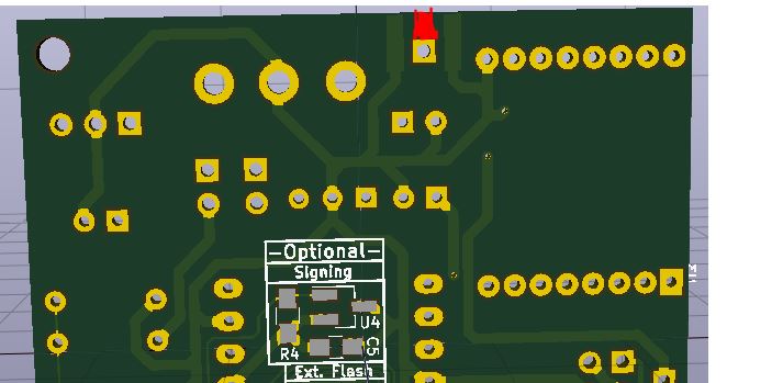
This area that I have painted red. -
This area that I have painted red.@mickecarlsson - aha!! Okey, no problems :) I will just double-check this will not cause any issues with a SMA antenna.
-
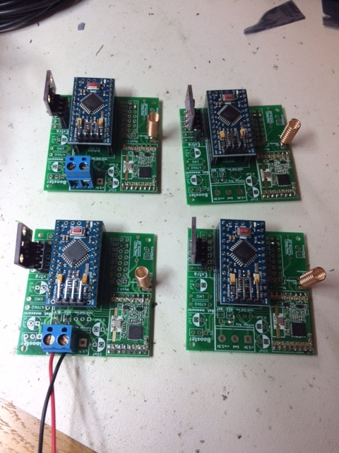
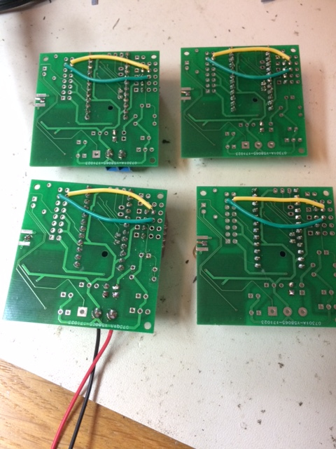
I have just finished soldering my last four easypcb with BME280:
-
I have just finished soldering my last four easypcb with BME280:
@mickecarlsson - Woao - looks great!
If you do that many with Ic2 i can understand you want extra area to be extended ;) I will think about it or maybe I can do a MysX daugherboard to you instead.Can I use your pic as a good example on the openhardware page?
-
Yes, you can use the pictures. If you need better pictues I can provide it to you.
-
@mickecarlsson - Woao - looks great!
If you do that many with Ic2 i can understand you want extra area to be extended ;) I will think about it or maybe I can do a MysX daugherboard to you instead.Can I use your pic as a good example on the openhardware page?
-
@sundberg84 are you going to test the SPI Flash with FOTA? at least to get an idea of the compatible chips that can be used.
@gohan that was my plan. What is your thought s about this ? I have never used fota or spi flash.
I'm not a software guy though... I can test hardware.
-
Everything is going fine so im taking this to the next level... from test to produktion.
This sensor might be my most important summer sensor from now on ;)
A couple of days ago I had some friends over which gave me a beer cooler, garden edition.
Its pretty much a barrel in the ground which cools the beer down... (a bit atleast).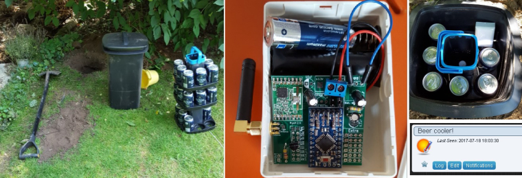
I must say Im very impressed with the RFM69 so far... except the price, there has been no trouble at all. No repeaters, no capacitors, no fine tuning... nothing. Pretty much solder 'n' play!
This node is burried in the far end on the garden (25m) and has to penetrate 3 concrete + 1brick wall to reach the GW in the celler... no problems, first try and bang!
So far... the temperature in the cooler isnt very impressive, and I have only tried the first layer. I was afraid I would loose radio coverage if I put the sensors far down... but I will try.
Cheers mates!
@sundberg84 said in 💬 Easy/Newbie PCB (RFM69 HW/W edition) for MySensors:
Everything is going fine so im taking this to the next level... from test to produktion.
This sensor might be my most important summer sensor from now on ;)
A couple of days ago I had some friends over which gave me a beer cooler, garden edition.
Its pretty much a barrel in the ground which cools the beer down... (a bit atleast).I must say Im very impressed with the RFM69 so far... except the price, there has been no trouble at all. No repeaters, no capacitors, no fine tuning... nothing. Pretty much solder 'n' play!
This node is burried in the far end on the garden (25m) and has to penetrate 3 concrete + 1brick wall to reach the GW in the celler... no problems, first try and bang!
So far... the temperature in the cooler isnt very impressive, and I have only tried the first layer. I was afraid I would loose radio coverage if I put the sensors far down... but I will try.
Cheers mates!
Hi, nice set-up. I have been reading this and havong a "newbie" question. I have a Newbie PCB build with the Nrf24l01+ which seems to give (me) a poor range.
So would that improve having a rfm69 instead? Or will just adding an antenna improve the reach (I have more or less the same outside distance and concrete wall/ flooring I'd liek to cross). Now I just have a reach for approx 8 meters and one concrete floor (inside the house)? Which is not very good (even my z-wave devices are preforming much better - outside at 20 mtr from the house.
Can the nrf240 be improved or do I need teh rfm69 (or even using a LORA ?). -
I would get better quality nrf24 modules and using a PA LNA one on the gateway may also help. Sure the rfm69 at 433MHz can have a better wall penetration, but I think you can do with better radios. Look for CDEByte store on aliexpress, they have good radio modules. Also a poor quality power supply can reduce the effective range.
If you want to try the RFM69 radios, you can "convert" the ones you have with this https://www.mysensors.org/hardware/nrf2rfm69 -
I would get better quality nrf24 modules and using a PA LNA one on the gateway may also help. Sure the rfm69 at 433MHz can have a better wall penetration, but I think you can do with better radios. Look for CDEByte store on aliexpress, they have good radio modules. Also a poor quality power supply can reduce the effective range.
If you want to try the RFM69 radios, you can "convert" the ones you have with this https://www.mysensors.org/hardware/nrf2rfm69@gohan said in 💬 Easy/Newbie PCB (RFM69 HW/W edition) for MySensors:
I would get better quality nrf24 modules and using a PA LNA one on the gateway may also help. Sure the rfm69 at 433MHz can have a better wall penetration, but I think you can do with better radios. Look for CDEByte store on aliexpress, they have good radio modules. Also a poor quality power supply can reduce the effective range.
If you want to try the RFM69 radios, you can "convert" the ones you have with this https://www.mysensors.org/hardware/nrf2rfm69So these would be better?
https://nl.aliexpress.com/item/E01-ML01DP5-Ebyte-2-4GHz-20dBm-2100m-nRF24L01-SPI-Wireless-transceiver-module/32638720689.html?spm=a2g0s.13010208.99999999.336.T3AfNk
https://nl.aliexpress.com/item/CDEBYTE-2PCS-Lot-E01-ML01D-Wireless-Transceiver-For-Arduino-nRF24L01-2-4GHz-Antenna-Module-For-Microcontroll/32803704874.html?spm=a2g0s.13010208.99999999.333.T3AfNk
https://nl.aliexpress.com/item/CDEBYTE-2PCS-Lot-Special-promotions-1800-meter-long-distance-nRF24L01-PA-LNA-wireless-modules-with-PCB/32803720600.html?spm=a2g0s.13010208.99999999.330.T3AfNkIf I use one with PA_LNA on my Gateway are the pin-out the same as for the nrf24l+ as in the mysensors gatweay example?
Also there are models with nrf24l+PA what is the difference with the nrf24l+ ones? -
Yes those. Pa stands for power amplifier, lna stands for low noise amplifier and it is used to amplify incoming signal to boost low signals. For gateway it is better to use these with the higher gain antenna, on the node it is up to you according to the size constraints you may have.
Hello! It looks like you're interested in this conversation, but you don't have an account yet.
Getting fed up of having to scroll through the same posts each visit? When you register for an account, you'll always come back to exactly where you were before, and choose to be notified of new replies (either via email, or push notification). You'll also be able to save bookmarks and upvote posts to show your appreciation to other community members.
With your input, this post could be even better 💗
Register Login