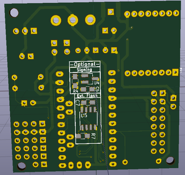
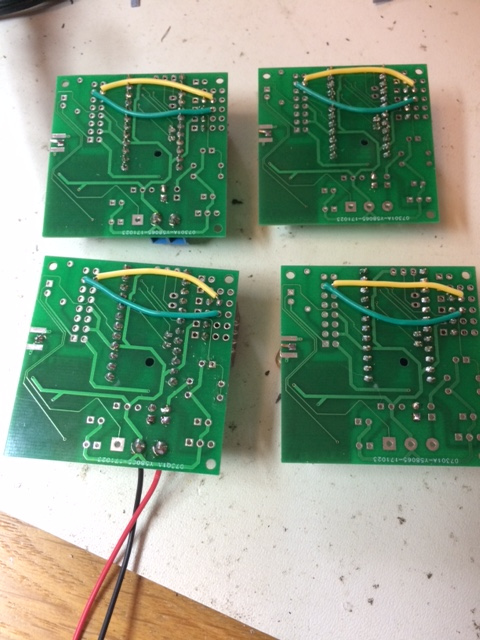
๐ฌ Easy/Newbie PCB (RFM69 HW/W edition) for MySensors
-
Well, since I posted the thread without it was finished (not usually my way of working) I can keep you updated on the work i guess... get input on the way.
New schematics made... not final! Not implemented any booster yet.
-
@gohan - looking better on that SMA connector...
Anyone knows if its possible to have a SMA and Hole for DIY antenna on the same PCB like this?
Edit:
Well, so far tonight... a couple of hours work and im happy some small stuff to fix before production.
-
Looking forward to buy this board. Thanks for including SMA connector. Now it's complete board for me
-
OK - beta release.
I have updated the description, bom, gerber files and kicad files on openhardware.io.
I have placed an order for fast delivery on pcbway.com but it will take some time before my RFM69 radios reach me from china-land. So I won't be able to test it for some time.IF you are curoius (and willing to debug and cut / resolder if there are errors) feel free to download the gerbers and place an order. I cant promise its 100% (or work as intended) and because of that I wont add them for sale on openhardware.io yet.
-
@sundberg84 I did this in my take of a SMA with a wire Antenna option:
, you can see more details here https://www.openhardware.io/view/388/RFM69HW-Arduino-Mini-Pro-Shield.
Haven't tried with the wire antenna trough.
-
Actually it seems a good solution to have the hole on the sma pad
-
@jlaraujo , @gohan - I does look really good and effective!
Would be great if you could test it! At the moment I have placed my order so I cant change it for this run, but out of experience there will be other stuff I want to change.Thank you for input! I greatly appreciate it!
-
This post is deleted!
-
So, this temporary GW is now connected to Domoticz and running at 34800 baud rate (had some problems to figure this out...) I have one (fake) node connected but still have some range issues to sort out. Most likley because of the DIY antenna...
-
I now have a gw and node working together on 3.3v and 433mhz (not HW version). I would say its quite safe to order the PCB if someone wants to try it out.
Note to myself and others... the RFM69 is really sensitive to high power. I fried one because I tried it on a Nano which i think is using 5v on its gpio. I was just thinking... hmm 3.3v - nano got one of those!
-
And now I also have a batterynode working... Power consumtion will come later... it works atleast
Someone that can guess what kind of power consumtion this setup would be (removing LED / regulator)?
-
@sundberg84 said in Easy/Newbie PCB (RFM69 HW/W edition) for MySensors:
I now have a gw and node working together on 3.3v and 433mhz (not HW version). I would say its quite safe to order the PCB if someone wants to try it out.
Note to myself and others... the RFM69 is really sensitive to high power. I fried one because I tried it on a Nano which i think is using 5v on its gpio. I was just thinking... hmm 3.3v - nano got one of those!
It's in datasheet that it is not 5v tolerant and absolute max voltage it's like 3.6v
-
@gohan - I was fooled by that the Nano got a 3.3v output... stupid.
-
Yeah, that's a noob's mistake
Pro mini 3.3v is the only way
-
So I have made the adjustment for low power/battery mode (removed the LED, voltage regulator and sleeping most of the time).
Im having a hard time to trust my Multimeter at this point... showing 5.1uA in sleep() mode while sending shows almost 2mA! This cant be right???
At the moment im all out of boosters... I was sure I had more so I didnt order.
What I have done now is uploaded a sketch sleeping 15min, running the vcc check (since I dont have a booster) and reporting it back to me. Lets see what happens...
-
To answer my own question I found this thread where he gets the exact same sleep current as I do (5.2uA). Still wondering about the high send current though.
Is 2.0mA a normal power consumption for RFM69W when its transmitting? Will investigate but all input appreciated...
-
@sundberg84 no. It should consume 16-45 mA. See datasheet.
-
@mfalkvidd - thanks. Have to recheck... maybe 2mA was during loop and there was a peak up which I didnt notice when transmitting. * feeling a bit more confident *
-
Hello,
Very nice job (as usual).
I think the first version was produced with Eagle. Can you post the Eagle version of the schematics and pcb ?
Thank you.Qq.
-
@qqlapraline - Hi!
Only the nrf24l01+ edition is made with Eagles. I used to make everything there but have moved to kicad now. The RFM69 edition is only made in Kicad only - sorry.
-
Update on the batterystatus as well while i write here. The node is still going strong at 3.2V so 5uA in sleep seems to be correct. I would say the battery function is working as well as expected so in all the major functions of this PCB is tested and passed!
-
Everything is going fine so im taking this to the next level... from test to produktion.
This sensor might be my most important summer sensor from now on
A couple of days ago I had some friends over which gave me a beer cooler, garden edition.
Its pretty much a barrel in the ground which cools the beer down... (a bit atleast).I must say Im very impressed with the RFM69 so far... except the price, there has been no trouble at all. No repeaters, no capacitors, no fine tuning... nothing. Pretty much solder 'n' play!
This node is burried in the far end on the garden (25m) and has to penetrate 3 concrete + 1brick wall to reach the GW in the celler... no problems, first try and bang!
So far... the temperature in the cooler isnt very impressive, and I have only tried the first layer. I was afraid I would loose radio coverage if I put the sensors far down... but I will try.
Cheers mates!
-
just add another sensor with a wire to reach the bottom of the barrel and you can see the temperature difference
-
@gohan - doh! Thats great... but no sport when you are testing the limits on the radio
-
it was just a scientific curiosity to see the actual difference in temperature, if any
-
@gohan - it is... I will add it, and to test the radio I could put the radio at the bottom and the wire to the top
-
@sundberg84 add a weight sensor at the bottom and you'll know when it is time to restock on beer
-
@mfalkvidd - I just love the way you are thinking
-
Hi there,
I have a little problem that you could probably answer. I built 3 temperature/humidity sensor nodes with this pcb mainboard. The sensors are BME280. The nodes are powered the following way:
- Phone charger 5V->3.3V (works good)
- 18650 battery (one piece), working good, but just for 2-3 weeks.
- AAA batteries (2 pcs), working good, but just for 1-2 days and the batteries are dead.
The power consumpntion is very high and i don't know why. Is it the BME sensor? What if I use DHT22?
ps: the sleeping time is 90 seconds and the nodes only sending status if something changes, otherwise not. Tha regulator and led desoldered from the pro mini.
Thank you for helping me out, I was very unlucky with nrf radios and this is the reason i try with rfm, but I almost give up (read all the forums to find out what is the problem and i cannot find it) :(:(
-
@ZsoltZombori - hi!
Some basic things- Did you remove the led and voltage regulator on the Pro Mini?
- Are you using a booster or did you lower BOD to stretch the power?
I would use a multimeter in series with your battery input (before the PCB) and read how much currentdraw you have. The aim should be below 100uA. Another tip if you have a power-hungry sensor is to power it from a digital pin and set the pin low before you sleep the node.
-
@sundberg84 Dear sundberg,
-
I desoldered the voltage regulator and the power led from all my pro minis to prevent unnecessary consumption.
-
Yes, I'm using a booster like this
My multimeter is not sensitive enough to measure as small ampers. I will write in the sketch to power the sensor from a digital pin and try out this.
Thank you for the tips
-
-
@ZsoltZombori - the booster you are referring to seems to be a step-down converter from 5v as well... I have never seen these before and can't unfortunately say how they work.
Another tip without the multimeter is to write a batterysketch and remove the sensors and see over some days how the battery reports back.
-
There is no datasheet for that buck boost so it is hard to have an estimate of its standby current. It would interesting to find out how it works.
-
@sundberg84 - Thank you for the tips, I'll write a battery sketch as you suggested and check the voltages. I'll reply with the results.
- And let me ask one more question; with switched off or lower BOD is it possible to reach longer battery life?
-
@ZsoltZombori - I have DHT22 nodes running for 1.5years now, so yes! You need to find your way to build the node with your sensors so the currentdraw is minimal.
-
@ZsoltZombori you get a bit longer battery life because the bod will not kick in, but if you have something draining the power it will not solve the problem
-
@ZsoltZombori - just to be clear, its either BOD or booster. They have the same result. BOD lowers the minimum voltage threshold before the chip dies, and the booster regulates the voltage up so the chip doesnt die. Same result, different methods.
-
@sundberg84 - Ah, I see. Thank you for this information. I'll check the consumption of the node itself then with BME280 attached to find out which component is the highest power consumer.
-
@sundberg84 - I attached the BME280 to D5 to switch on/off (to achieve less power consumption) but if I upload the program the module powers up, and connecting, send a measurement with temp, hum, bat and goes to sleep than wake up, and does nothing. If I attach the sensor to normally VCC + GND, it works fine. How can it be? What could be the problem?
-
@ZsoltZombori - Did you put the pin HIGH before read? (Comfirm with a multimeter?) If you did, you might want to add a wait(); before the readings so the sensors gets time to stabilise?
Or the BME module needs some sort of initialization/startup after powered on?
-
I think you need to reinitialize the sensors before you actually read it after you power it down. I suggest you remove the instructions in setup and put everything in a function that you call every time you read the sensor, where in the beginning you set pin D5 high and at the end you set it low.
-
@sundberg84 - Very good tip, I read the datasheet of bme280 sensor and it need time to initialize. I added 10 ms wait to program,
@gohan - I made a very beginner mistake as you said. The wire.begin was added to setup, I wrote it to loop, but it is not working..
-
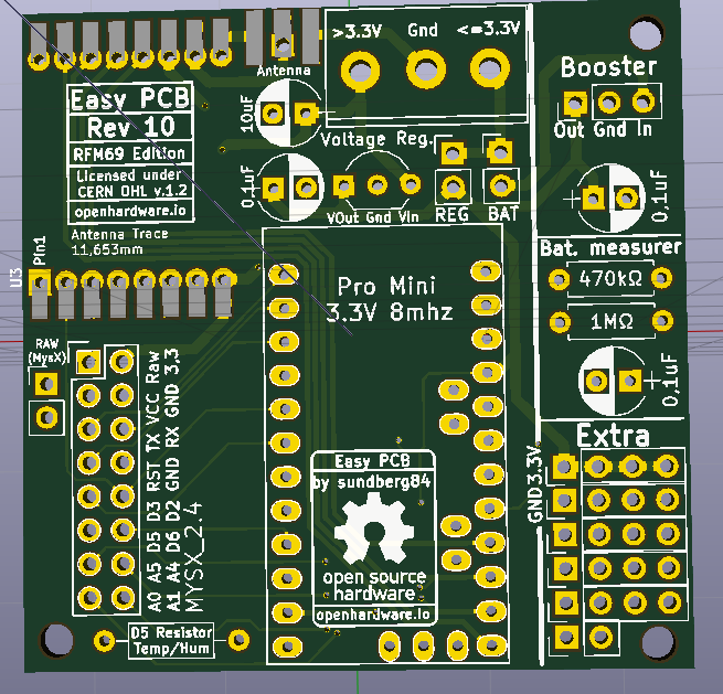
Some initial changes for Rev 10.
- MysX location changed to accept more MysX boards and align like Nrf24 version.
- Antenna location changed, radio rotated 180 degrees
- Optional signing added
- Optional SPI flash added.
- Extra pins aligned to 2.45 vertical & horizontal
- Relocated Extra + Bat Measurer some to allow more space to booster
- Pinholes added for RFM Radio
- Changed pull-up resistor from D3 to D5 to have one more pin for Interrupt
-
Are there any arduino pin left that could be connected to the "extra" area?
-
@gohan - yes, but then you are not free to use the extra area as you like.
-
In that case a trace cut would solve the problem
-
@gohan isn't a trace cut harder to achieve than solder a wire to the right pin?
-
I don't know, but it has been quite tedious to bridge the pins that were just next to the "extra" area to test the fota.
-
Please make the pad for the antenna on the "bottom" larger, same as "above". Most ready-made antennas are with a 90 degree wire for easier soldering.
-
Proposal.
Make two of the pads at the extra area with A4 and A5 (I2C) as more and more sensors are I2C.
Preferably the two pads next to VCC and GND.
Like the BMP280 and BME280, they are I2C with VCC, GND, SCL and SDA, so first line of pins in the extra area should be:
VCC o-o-o-o
GND o-o-o-o
A5 -o o o o
A4 -o o o oThe new layout with the SMD on the bottom layer looks good.
-
@mickecarlsson - im not sure what you mean with:
make the pad for the antenna on the "bottom" larger, same as "above"
Picture?
I was thinking about I2c but the problem is that different sensors use different pin-orders.
Also see the discussion with gohan above about extra area.
-
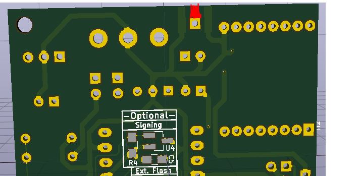
This area that I have painted red.
-
@mickecarlsson - aha!! Okey, no problems I will just double-check this will not cause any issues with a SMA antenna.
-
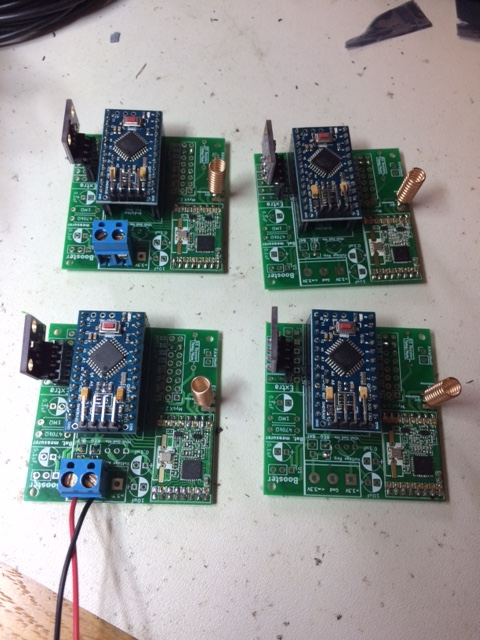
I have just finished soldering my last four easypcb with BME280:
-
@mickecarlsson - Woao - looks great!
If you do that many with Ic2 i can understand you want extra area to be extended I will think about it or maybe I can do a MysX daugherboard to you instead.Can I use your pic as a good example on the openhardware page?
-
Yes, you can use the pictures. If you need better pictues I can provide it to you.
-
@sundberg84 are you going to test the SPI Flash with FOTA? at least to get an idea of the compatible chips that can be used.
-
@gohan that was my plan. What is your thought s about this ? I have never used fota or spi flash.
I'm not a software guy though... I can test hardware.
-
The hardest part of fota is to wire the spi flash, the rest it is quite easy once you have the mycontroller installed. I can help you out if you want
-
@sundberg84 said in Easy/Newbie PCB (RFM69 HW/W edition) for MySensors:
Everything is going fine so im taking this to the next level... from test to produktion.
This sensor might be my most important summer sensor from now on
A couple of days ago I had some friends over which gave me a beer cooler, garden edition.
Its pretty much a barrel in the ground which cools the beer down... (a bit atleast).I must say Im very impressed with the RFM69 so far... except the price, there has been no trouble at all. No repeaters, no capacitors, no fine tuning... nothing. Pretty much solder 'n' play!
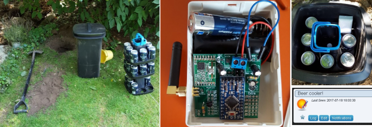
This node is burried in the far end on the garden (25m) and has to penetrate 3 concrete + 1brick wall to reach the GW in the celler... no problems, first try and bang!
So far... the temperature in the cooler isnt very impressive, and I have only tried the first layer. I was afraid I would loose radio coverage if I put the sensors far down... but I will try.
Cheers mates!
Hi, nice set-up. I have been reading this and havong a "newbie" question. I have a Newbie PCB build with the Nrf24l01+ which seems to give (me) a poor range.
So would that improve having a rfm69 instead? Or will just adding an antenna improve the reach (I have more or less the same outside distance and concrete wall/ flooring I'd liek to cross). Now I just have a reach for approx 8 meters and one concrete floor (inside the house)? Which is not very good (even my z-wave devices are preforming much better - outside at 20 mtr from the house.
Can the nrf240 be improved or do I need teh rfm69 (or even using a LORA ?).
-
I would get better quality nrf24 modules and using a PA LNA one on the gateway may also help. Sure the rfm69 at 433MHz can have a better wall penetration, but I think you can do with better radios. Look for CDEByte store on aliexpress, they have good radio modules. Also a poor quality power supply can reduce the effective range.
If you want to try the RFM69 radios, you can "convert" the ones you have with this https://www.mysensors.org/hardware/nrf2rfm69
-
@gohan said in Easy/Newbie PCB (RFM69 HW/W edition) for MySensors:
I would get better quality nrf24 modules and using a PA LNA one on the gateway may also help. Sure the rfm69 at 433MHz can have a better wall penetration, but I think you can do with better radios. Look for CDEByte store on aliexpress, they have good radio modules. Also a poor quality power supply can reduce the effective range.
If you want to try the RFM69 radios, you can "convert" the ones you have with this https://www.mysensors.org/hardware/nrf2rfm69So these would be better?
https://nl.aliexpress.com/item/E01-ML01DP5-Ebyte-2-4GHz-20dBm-2100m-nRF24L01-SPI-Wireless-transceiver-module/32638720689.html?spm=a2g0s.13010208.99999999.336.T3AfNk
https://nl.aliexpress.com/item/CDEBYTE-2PCS-Lot-E01-ML01D-Wireless-Transceiver-For-Arduino-nRF24L01-2-4GHz-Antenna-Module-For-Microcontroll/32803704874.html?spm=a2g0s.13010208.99999999.333.T3AfNk
https://nl.aliexpress.com/item/CDEBYTE-2PCS-Lot-Special-promotions-1800-meter-long-distance-nRF24L01-PA-LNA-wireless-modules-with-PCB/32803720600.html?spm=a2g0s.13010208.99999999.330.T3AfNkIf I use one with PA_LNA on my Gateway are the pin-out the same as for the nrf24l+ as in the mysensors gatweay example?
Also there are models with nrf24l+PA what is the difference with the nrf24l+ ones?
-
Yes those. Pa stands for power amplifier, lna stands for low noise amplifier and it is used to amplify incoming signal to boost low signals. For gateway it is better to use these with the higher gain antenna, on the node it is up to you according to the size constraints you may have.
-
@mr_sensor I have the same experience. A good gateway radio is important. I also use a amplified version. Sometimes it has been poor radio clones that make the bad range as well. Even if you don't have a amplified radio 8m+ 1 wall should be possible.
-
@sundberg84 @gohan Ok thanks for the input I will order some of the extended ones and see if thing s will improve.
-
@mr_sensor said in Easy/Newbie PCB (RFM69 HW/W edition) for MySensors:
@sundberg84 @gohan Ok thanks for the input I will order some of the extended ones and see if thing s will improve.
The parts mentioned above arrived. I thought just swapping the radio's and see if there is any improvement. But it seems my devices are not happy with there new radio ? So are these new devices coming with the same pin-out and are they using the same library as the non amplified radio"s ? Or do I need to alter my sketches or wiring for it to work?
-
@mr_sensor i think it should be the same pin out. Gohan might now better on the amplified version. As I said I don't use those much.
What kind of error do you have now?
-
they both work fine for me, just define in code wether is HW version
-
@gohan Ok, what do you mean by "define HW" in code" ? This in my code:
#define MY_RADIO_NRF24
-
but this is RFM69 radio pcb not NRF24
-
@gohan said in Easy/Newbie PCB (RFM69 HW/W edition) for MySensors:
but this is RFM69 radio pcb not NRF24
I know but I am using the nrf24 pcb.Do I need to add something like this when using the AP version?
#define MY_RADIO_NRF24
#define MY_RF24_PA_LEVEL RF24_PA_HIGH
Or just #define MY_RADIO_NRF24
-
@mr_sensor correct. As I said I'm no expert with the amplified version but that looks ok. I suggest you try it out. If it's wrong you will get an error and you can post that .
-
You should be able to swap a regular nrf24 with a PA version without changing code, given you have a stable 3.3v supply that can handle extra power
-
This has now been updated to rev. 10. There are still some images left to change.
The gerbers has been updated and sent to manufacturer but it will take some days before they update.
Make sure it says rev5 before ordering.
-
@sundberg84 said in Easy/Newbie PCB (RFM69 HW/W edition) for MySensors:
This has now been updated to rev. 10. There are still some images left to change.
The gerbers has been updated and sent to manufacturer but it will take some days before they update.
Make sure it says rev5 before ordering.
Hello,
Thanks for creating these PCBs, it's great to have a stable base to work upon!
I want to make a daughter board using the MYSX connector but the pin choices are a little inconvenient. Like A0 is used by the battery voltage measure circuit, D2 is used by the RFM69 radio. Could you share your reasons for using these pins and whethe it is possible to use different pins?
Finally, I couldn't find instructions for adding the flash memory. That is a great addition to this board!
Cheers,
Birla
-
@prakhar-birla Hi!
The reason is that MysX is a fixed connector. This way you can make daughterboards. If the pins would be inconsistent it would not work. You can use these pins (A0 + D2) if you dont use it for radio or battery measurment.
I havent had time to make instructions for the flash memory, but there are several others on this site which have made that. Look around for @scalz work for example on openhardware.io
-
Hey @sundberg84,
Thanks for the clarification! I checked the spec docs for the MYSX connectors but they didn't mention any fixed pins, just the purpose/pin type. Anyway, for different MCU it will inevitably be different pins. On Arduino Pro Mini since there are only two external interrupts there's no escaping D2, the analog pin on the other hand in an easy fix either use a different pin for battery measurement (A6/A7 is only a via away) or a different pinout on the MYSX.
I couldn't find any instructions for the flash memory, please share a link when you can. Also is it possible to add it without the footprint on the PCB?
PS. I just ordered a set of 10 PCBs through Open Hardware
Cheers
-
@prakhar-birla - well the idea with MysX is that the pin-order is fixed so you can attach any daugherboard to it. If you start mixing the pins around you will not be able to transfer a daugherboard from one motherboard to another since they will be different. Im not sure how MysX would translate to other MCU but other have digital and analog pins as well - so it would be most possible to connect MysX to other mcu.
About the external interrupt you are right, there are 2 on the atmega328. On my Nrf24l01+ version you can use D2 as an interrupt but since the RFM69 radio uses this pin you can not on this version. D3 is your only choise and if you need more you might have to create an external circuit.
As I said, I havent had time to look over SPI flash instructions yet. I havent even tried it - this is a user request from this forum. You can search this forum for more information - like this: https://forum.mysensors.org/topic/3160/ota-flash-types-for-mysensors/
-
Hi @sundberg84, on Easy/Newbie PCB rfm69 version PIN3 of MysX connector is connected to 3.3V resp. to the output from voltage regulator. When I compare with Easy/Newbie PCB nrf24l01 version, MysX PIN3 is connected to input of voltage regulator (to 5V). Is this a mistake in design of Easy/PCB rfm69 version?
-
@ferro - Hi no - the RFM version is 3.3v only. nrf24 data pins are 5v tolerant but the rfm radio isnt so thats why.
-
@sundberg84 - ok thanks, it makes sense ;). I was asking because I connected your Dimmable Led Strip daughterboard via MysX to this Easy PCB. Dimmer daughterboard is providing 5V on PIN3 (when LM2940CT voltage regulator is used on it). This would bring 5V to output of voltage regulator on Easy PCB so I disconnected PIN3 connection between dimmer daughterboard and Easy PCB. I connected PIN3 from dimmer board by wire to >3.3V power input of Easy PCB instead. Other option I'm thinking of would be not using voltage regulator on dimmer daughterboard at all but use its 12V raw voltage provided by dimmer board via MysX PIN1 (+ raw jumper on Easy PSB) and use voltage regulator (LE33) on Easy PCB only.
-
Schematic rfm69 version.
Needs updating, as it shows nrf radio.
-
@njwyborn - you are correct, thanks for noticing! Its been corrected!
-
Hi, I've lipo battery pack with 4,2v maximum voltage (3,6v nominal). Can I safely use it with this board? Do I need any modifications?
-
@emdzej - I'm not sure but it's designed for 3.3v. you have to check the rfm radio for Max input voltage on VCC and io. I think it's 3.3v so you might have to regulate down your lipo battery to this.
-
Hi can you add the kicad files for the latest rev pls?
-
Has anybody any experience with pcbway? I ordered via the link provided here (7 weeks ago) and only received a message from paypal. I haven't gotten a tracking number and pcbway says they can't help me without an ordernumber (which I don't have).
-
@kiesel - i checked my page as well but I dont have any ordernumbers. I can see some orders to PCB way latest weeks and they are marked as "shipped".
@hek - do you have more intel on this?
-
I ordered the 3rd of september (paypal mail says this: tirs. 03. sept. 2019 13:04:13 CEST (UTC+2)), are there any orders around that time?
-
@sundberg84, I will try to solve this with @kiesel over PM.
-
Could you add a 5 pieces option? The reason is the danish customs slaps an additional "fee" of ~24eu on imports over 12eu from china.
PCBway let's you choose 5 pieces on their website.
I tried using the gerber files but before I can upload them there is a host of settings which I don't know how to set.
-
@kiesel - the number is set to 10 and this is nothing I can change, sorry. You can PM me about which setting you need to set and I can help you.
-
@sundberg84, I know this is already an old topic, but I was sure that I did read somewhere a sleep consumption of 5ยตA, so I'm not completely insane
I've had recently a question about this in the battery powered topic : https://forum.mysensors.org/topic/4796/battery-powered-sensors/248, because my setup with a modified pro mini (no led and no power regulator) and a connected RFM69HW only, was consuming a 133ยตA at sleep state.
@Yveaux pointed me to the fact that in the beginning of the site article https://www.mysensors.org/build/battery, it was mentioned that a 120ยตA was to be expected.So how did you get this 5ยต sleep consumption?
Is it the build quality of the pro mini?
I did a test with only a pro mini and the sketch of lowpowerlab and was also measuring 133ยตA.
-
@evb - Hi, to be hones I don't even remember. I dont have any exact equipment to measure except a normal multimeter, so that can be that my reading is way off, or it was without the radio? Sorry, no documentation about this and no memory at this point. But here is the battery of my EasyPCB RFM + Dallas temp sensor. I changed the batteries 3 months ago as you see and currently is about 87%.
-
@sundberg84 thanks for the update.
Is the graph done with Grafana & InfluxDb?
-
@evb - correct!
-
For those who use this wonderfull PCB, it is possible to use it with a regulated 5V input or with a lithium 3.7V battery :: with the following two actions:
-
as a booster use a "1.8V 3V 3.7V 5V to 3.3V Boost & Buck Low Noise Regulated Charge Pump 2 in 1 DC/DC Converter"
This will convert anything between 1.8 - 5V to 3.3V- works with regulated 5V down to 3.3V
- works with lithium battery that start at 3.7V above 3.3, and then after sometime the battery goes down less than 3.3 and is boosted to 3.3
-
connect the "BAT" jumper so that input goes through you DC/DC converter
-
-
-
@hlehoux - nice once! Thanks for sharing!