What did you build today (Pictures) ?
-
Today I have finished work on control center for my smart home. The box includes a Raspberry Pi 3, gateway, ethernet switch, power supplies 5V and 9V. Audio input jack, ethernet and AC line cabels out from the box. Maybe, a GSM module should be included to the free space too (i will thinking about...). I am going to install this box in the near future.
-
@kalina said in What did you build today (Pictures) ?:
ione di installare questa scatola
if I can know !! The audio socket what is it for ???
-
@sindrome73 said in What did you build today (Pictures) ?:
The audio socket what is it for ???
For connecting the audio system to the RPI3
-
@kalina
And then once connected to the Raspy ?? What are you doing?? And a new thing for me !!
-
@sindrome73 said in What did you build today (Pictures) ?:
@kalina
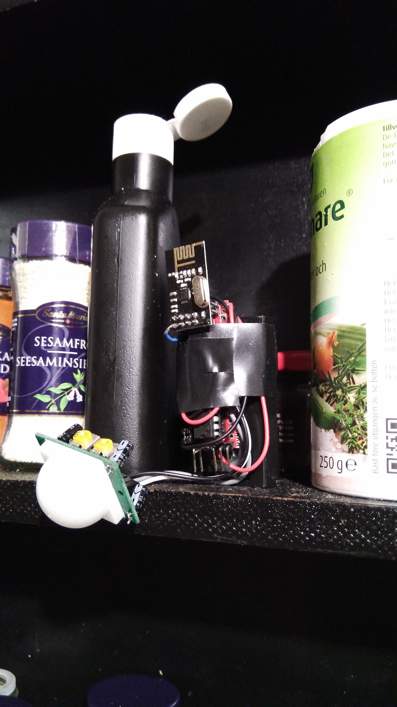
And then once connected to the Raspy ?? What are you doing?? And a new thing for me !!Maybe this picture will explain my intentions
-
Ok, now it's clearer
-
Today's work:
- Fixed https://github.com/mysensors/MySensors/issues/1096 (PR in progress)
- Fixed 60+ spelling mistakes in the example sketches https://github.com/mfalkvidd/MySensors/commit/6e7ee6ab30d503a6f288553689fdfbe645c931e6 (will submit PR when above PR is done)
-
My friend had a leakage from the water heater, luckily he was around (and renting) so not much damage was made, so inspired by the incident I made another water leakage sensor for water heater (reusing the code from my previous "ribbon cable sensor" )
Then I have an "alarm" flow in node-red (via openhab) which blinks all lights in the house, sends notification to mobile phones with high priority etc. Which brings me a lot of joy when all works fine (and annoys my wife, as usual)...
They are so easy to made that I might as well make a few of them just for convenience and "feeling rich with sensors" if you guys know what I mean
-
@dakipro what kind of setup do you end up with regarding bootloader / bod? What do you use to reprogram the pro minis bootloader?
-
@sundberg84 these run great on 1.8v BOD with some bootloader I found on the web (linked in the last post here ).
I use uno to flash the bootloader (tried with some IVRs but never got it to work, so just dedicated one uno prototyping hat for flashing) and then upload the sketch with IDE.
They are reporting battery from 2v to 3v (0-100%), and previous linked node is now reporting 51% of battery after 6 months, with sensor check every 2min and hearth beat every 4h.
-
Installed z-wave roller blinds (discussed on this topic) from Swedish company m.nu .
If all is great, I will order three more motors (and two knobs/switches) for living room and terrace doors (which should also automatically keep the shades open if doors er open, to prevent damage).
Made a basic node-red flow that uses xiaomi lux sensor to get them down, but ultimate goal is to have them understand when the light is very bright and when it is "cozy", perhaps even knowing to get the blinds just low enough. Found one good explanation on the internet, will check it out (perhaps use multiple lux sensors strategically placed around the room to determine sun position and strength). Any tips and tricks?
(gif of the action, cannot upload gif to the forum https://media.giphy.com/media/5aY6vSwVn1hsdYC6nd/giphy.gif )
-
I printed a small box and put my first "22" board in action on my entrance door. So far so good it's reporting the status reliably, and looking really tiny. A big difference with my first sensor 2 years ago in a big generic project box.
Just need to clean the glue left from previous sensor now
-
@nca78 said in What did you build today (Pictures) ?:
"22" board
Looks great, can we get more info about it/link?
-
I've continued my quest to get all MySensors defines documented, by creating some pull requests
https://github.com/mysensors/MySensors/pull/1111
https://github.com/mysensors/MySensors/pull/1108
https://github.com/mysensors/MySensors/pull/1106
https://github.com/mysensors/MySensors/pull/1105The only keywords left new are ones that I don't understand good enough to document. These are tracked in
https://github.com/mysensors/MySensors/issues/1107 and https://github.com/mysensors/MySensors/issues/1090
-
I also added buy links for a shielded PA+LNA module and a more reliable source for regular nrf24l01+, on request by @gohan who managed to dig up good Aliexpress buying sources. Thanks gohan!
The buying links are available at https://www.mysensors.org/build/connect_radio and https://www.mysensors.org/store/radio
-
@dakipro said in What did you build today (Pictures) ?:
Looks great, can we get more info about it/link?
Not really, I posted about it long ago here (https://forum.mysensors.org/topic/7836/what-did-you-build-today-pictures/136) It's just made for me to play by making a sensor as small as possible, but it's pretty hard to solder and with CR1632 and nrf22 the battery life won't be that good (around 1 year) so I don't think I'll publish it.
-
These arrived today...
New gateway and nodes with signing is first on my list.
-
Built half of my dutch bucket system. Namely the drain part. Irrigation to follow.
-
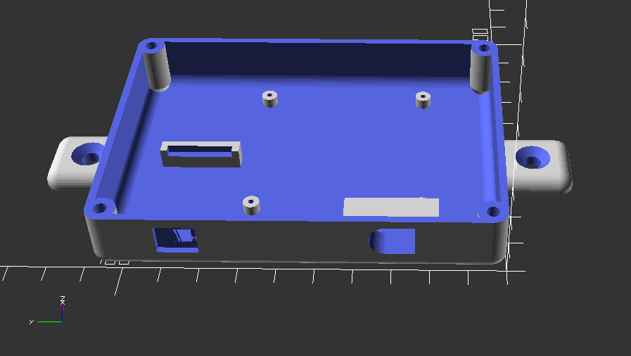
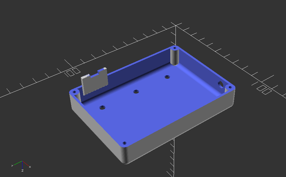
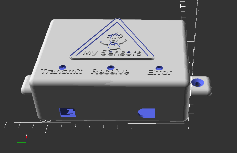
Working on setting up a new work bench in my back room in my basement where my HA equipment rack is. I wanted to build a case for my serial nRF24L01-PA-LNA gateway built on a rev8 Easy Newbie board. I just had the board sitting on a shelf on my rack, and now I want to mount it on my MDF board with all of my other equipment. Here is the design that I came up with for the case.
This is the inside bottom of the case:
And here is inside the top of the case:
It has a spot for 3 - 5mm LEDs for the transmit, receive and error lights. There is a hole on the right side of the case for the PA-LNA antenna connector. The oval hole on the lower right side of the case is for the DC in jack. I had one of these in my parts bin:
The hole on the bottom right is for the FTDI adapter connection. I am using one of these adapters that has a mini-USB connector:
I have the case running on the printer now. I will post pics when it is done.
-
@dbemowsk very impressed by your openscad designs, as always
-
For anyone interested, here is an OpenSCAD rendering of the MySensors logo:
I tried posting the OpenScad code for this, but it is too long to add to a normal post. So here is a link to the OpenSCAD file.
MySensors_logo.scadSpecial thanks to @hek for giving me the .svg file that allowed me to create this. I would be curious to see peoples uses for this.
-
So I tried printing the cover for this with my original design using Cura as my slicer, and I couldn't get the logo to print right, plus the text under the LEDs was a bit too small. I then modified the design a bit and made the logo and text a bit bigger. I again tried printing it using Cura, but the logo still was missing some lines in the body. I then thought that part of the problem was the slicer I was using, so I tried it using Slic3r and I have to say, the logo came out MUCH better.
I ended up losing the Y in "My" Sensors and the ending "t" in "Transmit", but I am going to use the case the way I currently have it. Now I just have to assemble the new gateway. I am planning on making a whole new gateway and trying out the new 2.2.0 library. Hopefully my older 2.0.0 nodes will not have any issues with it, but that is why I plan on keeping my pro mini from my 2.0.0 gateway so I can revert back to that if I have to.
-
Built case for soldering tools, to easily move them out of the way.
Not really, bought it on banggood and asked wife to assemble it (she likes those type of projects, especially if the office might look a tiny bit cleaner) https://www.banggood.com/DIY-Self-assemble-RC-Model-Tools-Case-Screwdriver-Box-Gripper-Package-Plier-Stand-Retro-Style-p-1257252.html?cur_warehouse=CN
Laser cut plywood(or something), looks quite nice I think. I will order few more when they appear in stock.
-
So here is my contribution to this tread: a differential drive "brain". A work in progress:
-
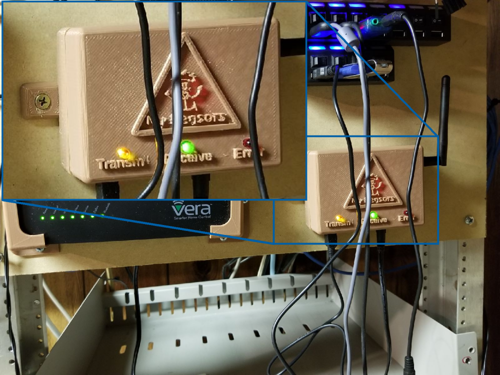
Finally finished my 2.2.0 gateway and have it mounted in the new enclosure. It appears to be talking to my 2.0.0 sensors just fine.!
-
Another motion and led strip node.
-
...and deployed.
-
Nice, maybe add a diffuser? I've found that greaseproof paper (smörpapper in Swedish) works pretty well.
-
@gertsanders what is that?
-
@sundberg84 Nice. I was wondering if I had an use for these. Now I want them everywhere!
-
@nagelc - easy to hide, looks good and awsome as night-lights for the kids. Its also a bit woav factor connecting them to a motion detector so they lights up when someone walks by.
-
Bathroom controller. It consist of a relaybox with a HLK 5v power source, it's hidden in the closet. Then I have realy to light, nightlight, mirrorheat, and extraction fan
And then the controller it self it's a Wemos D1 Mini Pro, Si7021 Temp/Hum, sensor and a PIR HC-SR501
3D file is created with Freecad, STL files are available here:
https://www.thingiverse.com/thing:2890456
-
@bjacobse Nice project. I like the 3D printed wall box. have you given any thought of having separate control of the lights and extraction fan? The reason I ask is that it may be beneficial to use the temp/humidity sensor to determine when the fan runs or gets shut off based on room humidity. This would be useful to reduce the chance of mold brought on by excess humidity.
-
@bjacobse don't you get false pir detections with the wemos that close to the pir sensor?
-
@dbemowsk Thank you
For now as it's in early stage, I use the left switch to switch on (when I goto shower)on manually the fan, mirror heat, fan, and light and nightlight for 10min.
the right switch is only to start the fan for 5 min
I have not yet added humidity to start extraction fan automatically, but yes I will add this to the ESPEASY, rules
-
@gohan
No, I have a fairly large electrolyte cap on power supply on the controller PCB, to stabilize the PIR/Wemod/si7021 power source.Actually when the bathroom door is open, and someone walk by the bathroom, the PIR will detect this and switch ON the light. I could consider to update 3D print to add a "wall" to block PIR.
The idea is that this PIR potentially can be used to connect to burglaralarm (but again I need to verify that I dont get false PIR reading due to sunlight)
-
I was asking because quite some people had issues with the PIR being too close to the antenna as the antenna during transmission was inducing some noise that triggered the sensor so they needed to move them apart to solve the issue
-
Depending on the number of simultaneously active relays and the weemos tx power requirements make sure you don't overheat the HLK module, fire hazzard.
My 8 relay board draws a whooping 500ma @5V when all of them are active.
-
@gohan thanks I didn't think of the RF transmission from Wemos should impact PIR sensor, I only have thought of the power ripple. how far distance should affect PIR? I think mine is approx 2 cm apart
-
@executivul
Good point, But I have looked at the power/current budget.
I have 4 pcs relay, JQC-3FF 5V DC, spec: https://www.futurlec.com/Relays/JQC-3FF-05.shtml uses 0,36W each x 4 pcs = total 1,44W.
Usage of Wemos D1 Mini Pro is unknown, at least there is no spec...https://wiki.wemos.cc/products:d1:d1_mini_pro#documentation let says it uses 1 W
HLK01 is rated to provide 3W
Should be all ok
-
@bjacobse I had problems with ~3-4cm. Lots of false triggers on the pir. But if you are not experiencing false triggers your setup is probably fine.
More info: https://forum.mysensors.org/post/78771
-
@mfalkvidd Thanks for the link to the post, I think I should upgrade and use aluminium foil as you done to make a GND shield around the PIR sensor
-
So I have uploaded the 3D design files for my MySensors gateway case to thingiverse for anyone that is interested.
https://www.thingiverse.com/thing:2904969
I have included the OpenSCAD file used to generate the .stl files. I would be interested in seeing posts of other makes or remixes of the design.
-
@dbemowsk Nice work!
Now that I finally own a 3D printer, I can't believe I waited so long to get one. I encourage anyone who doesn't yet have a 3D printer to get one too. Sharing enclosure files in addition to PCB designs is the next level.
-
@neverdie I can only agree - to buy ans use a 3D printer is really good and some fun too
-
@neverdie how are you getting on with setting the printer up? I have been struggling with the correct setting for some time with problems like the plastic would stick to the surface even though it is pre-heated. At the end I got really frustrated and retuned the printer. I am using www.3dhubs.com now if I need to print anything.
-
@alexsh1 What brand/model of printer were you using? Also, what type of plastic were you trying to print with?
-
@alexsh1 said in What did you build today (Pictures) ?:
@neverdie how are you getting on with setting the printer up? I have been struggling with the correct setting for some time with problems like the plastic would stick to the surface even though it is pre-heated. At the end I got really frustrated and retuned the printer. I am using www.3dhubs.com now if I need to print anything.
It's working like a dream with both PLA and PETG, which are the only plastics I've tried thus far. I'm using the Prusa I3 MK3 (Prusa's 4th generation 3D printer). Following dbemowsk's suggestion, I'm now using Octoprint, running on a Raspi3b, which is mostly useful for uploading print files and monitoring from a distance using a webcam. Honestly, though, once it gets past the first layer, I haven't had any failures, so the webcam probably isn't needed at all.
-
@dbemowsk I was using PLA. The printer was the most popular model on Amazon.
That's the one:
-
@alexsh1 Strange, that looks like a pretty decent printer.
-
@alexsh1 You can buy PEI print beds as an add on for most printers. Maybe that might have helped your issue. When printing PLA, I print a 5mm brim on the first layer, and that keeps the print object from prematurely dislodging later. Haven't needed a brim though when printing PETG, which just naturally bonds very strongly to the PEI print bed.
If there are going to be failures, they'll probably happen in the first layer. Once you get beyond that, it's smooth sailing.
-
@neverdie said in What did you build today (Pictures) ?:
If there are going to be failures, they'll probably happen in the first layer. Once you get beyond that, it's smooth sailing.
That's exactly what happened. The first layer simply would not stick to the surface. Especially, if it is, say, a larger project box. For small items - no problem.
I must admit I did not spend too much time on this. I tried it for a week and then just returned it. Too much trouble for occasional prints I do.
-
@dbemowsk It is a good printer I suppose. I only used PLA and just did not spent too much time trying to find the right settings. Given that a few prints I ordered were also warped at the first run, I concluded that this is still at the DIY stage.
I'll probably get a printer when technology is going to be more advanced.
-
@alexsh1 NO problem. I realize they are not for everyone.
-
Finally, I can join this discussion!
Today I drew a scheme of my first device! This is a system to protect against water leakage. I also posted it in the "hardware" section. Link.
-
A temp-node on 2xAA. Also a sneak-peak on EasyPCB rev 10...
MySensors Battery Node 2xAA - EasyPCB (Nrf24l01+) and Temp Sensor. – 17:53
— Andreas Sundberg
-
@sundberg84 Which microscope are you using, looking 8:07 into your video?
-
@bjacobse it's the cheapest one on eBay with the software cheese on Linux. I think it's a replica on Andostar x500 so search Usb microscope Andostar and you will find.
-
@sundberg84 very professional video with multiple camera angles. Great work!
-
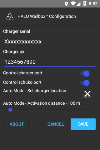
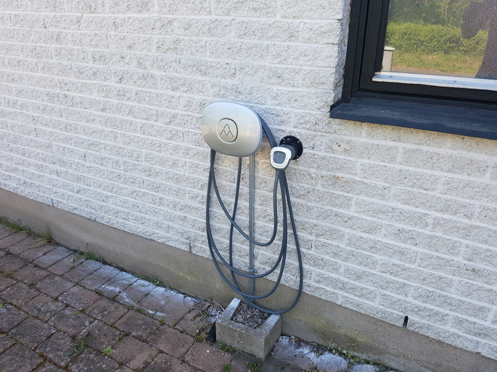
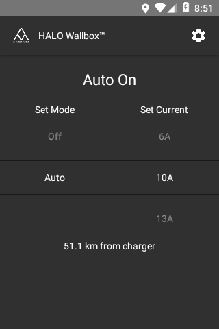
I've been busy this week building my first native android app in (nativescript-vue). It will control my new car charging station (HALO Wallbox). The charging port will automatically turn on when I'm closing in to our house and turn off off when leaving the area.
-
@hek Is that to prevent others from using it?
-
@NeverDie, yes, and to have a small project to learn app development.
-
One of three ongoing projects:
lasercut box
atmega1284p based
DS3231 rtc (very accurate and 2 alarms!)
LDR
20 by 4 LCD, two sizes of numbers, menu driven setup
buzzer
leds for moodlighting
doppler for proximity detection
encoder for scrolling through values (for setting time)
buttons with LED feedback for interactivity
mp3 player
most interface objects MySensorisedThis entry is to boost my energy, because we are still a long way from home (pcb is still not made, focus is now on prototype and software).
-
I love the design of the air vent on the righthand side of your laesrcut box. Does that pattern have a name?
-
@neverdie nope, but it is inspired by oriental frames, I just made that based on what I saw on one of my cabinets (which I bought while living in Singapore).
-
@neverdie I will publish the project once it has advanced a bit more (still need to design the PCB for this box).
-
@sundberg84 how is the rev10 progress going? I am about to order a batch of EasyPCB but want the new bells and whistles
-
@gertsanders Cool. You might like this pattern also then:
-
@neverdie That's cool. Kind of like an overlapping honeycomb design.
-
@mickecarlsson except I have not yet tested the new things on the back (signing and extra flash) the boards are working. I will try to test the last things before May is over and the publish.
If you want to order I can offcourse email you the Gerber's but on your own risk.
My first experience with the board is that it's performing better than Rev 9 with the new position if the hardware. Also the ground plane helps.
-
@neverdie that is a nice pattern. I found that these things need time to draw. If anyone has a DXF file, I would love to try it.
-
@sundberg84 thanks for the offer, I can wait for the final, no worries. Do you have a list of the new components added on the back?
-
@dbemowsk said in What did you build today (Pictures) ?:
@neverdie That's cool. Kind of like an overlapping honeycomb design.
Bingo! Looks like that's exactly what it is. A small honeycomb superimposed on a bigger one.
-
@neverdie I created that basic pattern in OpenSCAD.
Here is the scad
$fn = 6; fudge = 0.01; pi=3.1415926; large_diameter = 40; circumradius = large_diameter/2; inradius = circumradius/(2*tan(180/$fn))-1; height = 2; line_width = 1; rotate([0, 0, 0]) hollow_cylinder(large_diameter-line_width, height, line_width); for(i=[1:$fn]) { rotate([0, 0, (360/$fn*i)+30]) translate([inradius, 0, 0]) rotate([0, 0, 30]) hollow_cylinder(circumradius, height, line_width); } module hollow_cylinder(diameter=10, thickness=2, line_thickness=2) { difference() { cylinder(thickness, d=diameter); translate([0, 0, -fudge/2]) cylinder(thickness+fudge, d=diameter-(line_thickness*2)); } }
-
Expanding on that, I mapped it out further to give people an idea of how it's calculated.
And the scad based on my previous post.
$fn = 6; fudge = 0.01; pi=3.1415926; large_diameter = 40; circumradius = large_diameter/2; inradius = circumradius/(2*tan(180/$fn))-1; height = 2; line_width = 1; for(i=[1:$fn]) { rotate([0, 0, (360/$fn*i)+30]) translate([inradius*2, 0, 0]) rotate([0, 0, 30]) honeycomb(); } module honeycomb() { rotate([0, 0, 0]) hollow_cylinder(large_diameter-line_width, height, line_width); for(i=[1:$fn]) { rotate([0, 0, (360/$fn*i)+30]) translate([inradius, 0, 0]) rotate([0, 0, 30]) hollow_cylinder(circumradius, height, line_width); } } module hollow_cylinder(diameter=10, thickness=2, line_thickness=2) { difference() { cylinder(thickness, d=diameter); translate([0, 0, -fudge/2]) cylinder(thickness+fudge, d=diameter-(line_thickness*2)); } }
-
@mickecarlsson - sure.
Signing: atsha204a (sot-32-3), R4: 1k-100k resistor (0805), C5 0,1uF capacitor (0805)
Flash: R7: 56k-100k resistor (0805), C7; 0,1uF capacitor (0805), U5: AT25DF512C or equivalent SPI Serial Flash Memory (8-lead SOIC). I bought this from Germany (but not tested)
-
Yesterday I tested the new EasyPCB with RFM radio and hardware signing. Worked out as expected and I'm going to release all files soon.
I haven't tested the flash part yet but I'm hoping this is working as well.
This picture will be a part of a new video with me building my new RFM69 serial gateway using signing.
Anyone they can guess which issue I had when I took the photo?
Rev9 vs Rev10 (inkl signing) rfm gw
-
@sundberg84 the RFM69 is soldered 180 degrees wrong on the new board
-
@mickecarlsson interesting thought but no because the radio on rev9 isn't soldered in the image (but wrong rotated as you noticed). The hardware on that image is working. I added a HW radio without noticing so with the old code I just got no reply/Nack. I had to add the HW define.
-
Today I finally finished my second RGB LED lighting in the room. Next is the LED illumination of the perimeter of the bed. Under the bed, I want to place a motion sensor so that it reacts when I get out of bed at night.
-
Redesigning my nodes in the RFM69 network to be signed using EasyPCB 10. Today it was my beer cooler node (because it's very important the beer temperature is secured). In the same time I'm implementing @gohan idea with two temp points (top and bottom).
-
you could use this under the bed:
It works like an infrared sensor (same three pins), but it does not need a line of sight. It just reacts to movement as this results in a disturbance in the emitted radio signal. Works very well on my clock
The "high" value when movement is detected is not a full 5V, so I test the Out pin as an analog pin. Anything above 2.5V is an activation due to movement.
-
@gertsanders many thanks! This is very interesting, I did not previously hear about such a sensor.
I understand correctly that it can be placed in a wooden case and it can work through it? Since the tree does not reflect its waves.
If this is so, will not it respond to the movement of the bed frame or my movements when I'm on the bed?...
-
I tried some of those radar sensors and are very sensitive, they could detect even if you move in the bed. In addition I'd rather not sleep next to a 5 Ghz radar emitter
-
@gohan Is there a chance to wake up a little toasted?
-
fortunately the power is low, but still in the wifi power range and it is transmitting 24/7
-
@gohan Oh, pish posh. It's made in China and sold for peanuts! What could possibly go wrong?
-
I think it would be faster to answer to "what could possibly not go wrong"
-
@gohan What could possibly not go wrong?
-
So these radar motion sensors are actually quite impressive, the ones with just analog output only have 1 transistor, the rest of the circuit is formed by the pcb traces. Weird, but it works. They can be hacked (sawtooth wave for power) to give a distance reading instead of doppler. The signal processing is too much for an arduino, but it is doable.
The other ones actually use the same chip as the most common pir devices.
-
Suddenly my outdoor lightsensor stopped working. A good time to have a portal debugger. Everything seems fine in the log though... All ST:ok but for some reason it doesn't show up in domotocz.... Well that have to be tomorrows project.
-
Another node went down today... a repeater this time. Well... quickly a new one with additinal updates compared to old. (PA/Lna and Mysensors 2.3)
-
I made a working version of my test board with PCF85176 LCD driver, finally reaching some decently low current consumption for an always on display. There are still some possible gains to make with lower driver voltage, and with a more recent driver that should allow to go as low as 5uA.
-
Though not MySensors related, I thought I'd post my latest build that has been consuming a lot of my time lately. This is the main reason I haven't been on the forum much lately. I bought a drone kit recently. Here are some pics from the initial assembly:
Since the initial build I have flown it and from a hard landing broken one of the cheap plastic legs that it came with. I designed a replacement with my 3D printer and some 1/4 inch aluminum rod.
Here are some pics at it's current stage. I have designed and printed some prop guards and a few other add-ons:
I have also designed and built a small servo based 3 axis camera gimbal. The controller was built using one of my spare 5 volt pro minis and an MPU-6050 accelerometer. Still working on the parts that will attach it to the drone, and I still need to pick up an FPV camera to attach to it, but a simple FPV cam is cheap.
-
@sundberg84
Thank you Sundberg for your help, I now have received my own microscope, a reply to your comments from 1 or 2 months ago
-
@andrew have you also designed the power board or do you reuse the livolo's one?
-
@jeremushka I reused the top PCB (the touch panel) with its original microcontroller, but with a custom firmware. the bottom PCB was fully replaced with my own designed version. this includes the power supply with additional protections, atmega328, atsha and nrf radio.
it is running very well on my desk, but I was super busy in the past months so it is not yet installed to the wall.in parallel I also had to finish its opposite side, the controller at the lamp. it is also ready for final installation, I just need time for that
-
The other day I finished the first version of the PCB for my system of protection against water leakage. It will have two automatic ball valves, six leakage sensors with wire breakage monitoring and in the future I plan to connect it to the Mysensors.
Here is a prototype collected with the help of Arduino Pro Mini. Arduino Uno is just nearby, but not connected. Do not pay any attention to him.
-
@vladimir I gather you meant motorised ball valves rather than automatic, the automation being on the processor.
When you refer to leakage, is this to react to pipes potentially bursting or an external failure such as drainage failure in a cellar?
-
@zboblamont Yes, it is, motorized ball valves.
I meant the reaction to the breakthrough of pipes or flexible connections of sanitary ware.