What did you build today (Pictures) ?


  • @kalina said in What did you build today (Pictures) ?:

    I have assembled a few UPS ... now I am testing these hardware.

    Looks neat! How did you do the cutout of the sides of these enclosures?


  • Hardware Contributor

    @tsjoender said in What did you build today (Pictures) ?:

    Looks neat! How did you do the cutout of the sides of these enclosures?

    No magic, this is the work of the CNC...)))

    0_1537188188527_9a2275b5-cba5-4fcb-8189-2380b147e78c-image.png


  • Hardware Contributor

    Today I had the ladder so I could get on the roof so while there I changed batteries on my rain node.

    0_1538833034710_IMG_20181006_153329.jpg

    0_1538833043350_IMG_20181006_153345.jpg

    0_1538833090309_1538833076301772494958.jpg


  • Mod

    @sundberg84 But what did you build today? 😉


  • Hardware Contributor

    @yveaux nothing that I can post here unfortunately... only a ladder for my cat 😂 non automated.


  • It's a breakout for a Fanstel BT832 (NRF52832). Two experiments with this board, still a work in progress:

    • I wondered if it would be possible to hand solder to the LGA pads on the back of the BT832 using small plated thru holes (6 solder spots middle left in the first picture). Two pads connected. The rest did not. About what I expected.

    • Using just the microprocessor of the BT832 to make a LoRa node. (NRF5 radio turned off). So far the Ra-01 is not initializing. Edit (10/8). The RA-01 now initializes. I needed to update the pin assignments in MyBoardNRF5.h.

    0_1538864831322_20181006_182131.jpg 0_1538864849872_20181006_182139.jpg


  • Hardware Contributor

    @sundberg84 said in What did you build today (Pictures) ?:

    @yveaux nothing that I can post here unfortunately... only a ladder for my cat 😂 non automated.

    Just pretend you have automated your cat. We can't control from here.


  • Colleagues!
    I am writing in this thread, because here are the most active users of the forum and the system MySensors.🙌
    Perhaps you can help me with the solution of my problem: Improvement Xiaomi smart kettle (I need help!)
    Maybe you had similar projects...
    Then, I can finally publish a new project in this thread. ✌


  • Mod

    @vladimir please don't crosspost. Everybody is able to see the latest messages, so there is no need to point to your post from multiple threads.


  • @yveaux Excuse me. I promise not to do it again!🙆‍♂️


  • Hardware Contributor

    @Nca78 Well, i automated my cat door.

    0_1539065431649_79b5e042-89e5-42d2-b9ca-4bcde16f54c7-image.png

    0_1539065456891_8ed25e75-1db1-44cc-b317-55864bd74474-image.png

    0_1539065474883_1a733bca-4cfe-4df4-a5ca-0f34a193568d-image.png


  • @sundberg84 said in What did you build today (Pictures) ?:

    The rules are simple - keep it simple with one picture (or a few) with a small text including a small exp

    0_1539488433847_esplangatewah.jpg

    sick of breadboard so made the gateway more permanent. added a nice dc plug to it after pic


  • Hardware Contributor

    Playing with how small I could create a EasyPCB if I only used SMD components and footprints for both RFM69 and Nrf24l01+... including MysX, Signing, Flash offcourse... and a coincell...

    0_1539893069382_cb02fc1b-387a-48e0-b07b-36097509582a-image.png


  • Admin

    @sundberg84

    cool, what dimensions are you down to now?

    btw. what happened to the trace in lower right corner (the one that runs by the ISP connector)?


  • Hardware Contributor

    @tbowmo - Thanks!! 🙂 42mm diameter (round, but the 3d view doesnt show that).
    The track - well, it seems like I can only get KiCad to make 45dgr tracks... need to investigate it its possible to make other tracks...


  • @sundberg84 you can also use smd crystal. They are cheaply available on aliexpress. Are you using 0603 caps and resistors?


  • Hardware Contributor

    @monte - 0805 res/caps, (for me easy to solder, while 0603 is possible but start to get hard).
    I was thinking about SMD crystal but left it since i couldnt find a common size. Do you know a good size for SMD crystal (with multiple brands?) like 0805 or a good searchword? I found HC-49S but they are the same size as the ones with pins.


  • @sundberg84 "well, it seems like I can only get KiCad to make 45dgr tracks"

    References => General Settings => Limit graphics lines to 45 degrees


  • I recently hacked my Assa Abloy/Yale smart lock as it could only turn +-90° created a new washer ring, so it now can turn infinitely so it is usable to use a lock
    The needed 3D stl file or Freecad drawing is to be found here:
    https://www.thingiverse.com/thing:3155286


  • What an inspiring thread!


  • @sundberg84 I've bought these 5032 crystals: https://www.aliexpress.com/item/Free-shipping-20pcs-16-000MHZ-16mhz-20pF-2Pin-5032-smd-quartz-resonator-Crystal/32821974003.html but there are plentiful other offers on aliexspress and/or ebay. This 5032 package seems to be the most common. There is another package with the same size but with 4 pins 2 of which are not connected, I bought them from my local distributor, while was waiting a package from aliexpress. But those with 4 pins are harder to solder (obviously) and I don't see any pros of using them.
    The most suitable for hand soldering and easiest to find are these: 0_1540201979487_2014022559267404.jpg
    According to this image the ones I have are TX5 and TG5.


  • Hardware Contributor

    Im getting so tired of soldering extra wires and stuff so today im doing a "MysX to All common sensors breakout board"...

    0_1540411084071_4f9ac007-2ce9-41a9-8bc6-b954f193b964-image.png

    Dont know if this will work... but worth a shot.


  • Plugin Developer

    @sundberg84 If I'm honest some of those sensors seem 'old' to me.

    • I usually go for the BEM280 instead of the BMP085 and DHT22. It's so cheap now.
    • I never use pulse soil sensors, only the capacitive kind, as they last much longer and don't pollute the soil.

    In fact, I always make all my sensors with the Nano Wireless Expansion Board, which is about $2. You can simply plug in the NRF24 into it.
    https://www.aliexpress.com/item/Free-shipping-Nano-328P-IO-wireless-sensor-expansion-board-for-XBEE-and-NRF24L01-Socket-for-arduino/32264665470.html


  • Hardware Contributor

    @alowhum thanks for the reply!
    I used the sensor in MySensors build section, i somehow believe that is whats used the most. But that does not stop me from adding your suggestion for BEM280. That Wireless board looks great, but Im working with the MysX connector so thats why im making this board.


  • Hardware Contributor

    @alowhum said in What did you build today (Pictures) ?:

    • I usually go for the BEM280 instead of the BMP085 and DHT22. It's so cheap now.

    Unfortunately most of the cheap breakout boards found on AliExpress use clones with much worse specs than the original version

    In fact, I always make all my sensors with the Nano Wireless Expansion Board, which is about $2. You can simply plug in the NRF24 into it.
    https://www.aliexpress.com/item/Free-shipping-Nano-328P-IO-wireless-sensor-expansion-board-for-XBEE-and-NRF24L01-Socket-for-arduino/32264665470.html

    But you can't really make battery-powered sensors with those ? The regulators are AMS1117 with 5mA typical quiescent current.


  • @nca78 said in What did you build today (Pictures) ?:

    Unfortunately most of the cheap breakout boards found on AliExpress use clones with much worse specs than the original version

    Could you be more specific? How exactly worth specs does they have. Was going to buy a bunch of them. Maybe there is some comparison or tests?


  • Plugin Developer

    @sundberg84 yes, sorry about that, I realised too late that it's an expansion board.

    @Nca78 Thanks! That 5ma leak current was exactly the kind of info I needed about the board. I was wondering it if could be useful for battery powered things. None of my sensors are. Well, one - I used the BBC Micro:bit as a battery powered motion sensor.

    I guess not having a regulator on board is what makes the Arduino Pro Micro so good at being battery powered.

    Out of curiosity: if I attached the board to a Usb powerbank (say 10.000 Mah) to operate as an electricity led pulse sensor.. what would be an estimate for how long it would run?


  • Mod

    @alowhum rough calculation: 10,000/5 = 2,000h = 83 days. Lower if other componens also consume power.


  • Mod

    @monte clones use different components, so it depends on which clone.


  • Mod

    @alowhum said in What did you build today (Pictures) ?:

    I guess not having a regulator on board is what makes the Arduino Pro Micro so good at being battery powered.

    actually the better solution is the pro mini at 3.3v with regulator and led removed, and you can use an LDO regulator to power it with a LiPo cell or no regulator at all if you use a LiFePO4 battery. Using the arduino at 3.3v allows you to use all radio modules and all the low power sensors.


  • This is my new PSU - 3D printed enclosure and a few components
    It is very precise.

    2_1540841375727_3.jpg 1_1540841375727_2.jpg 0_1540841375727_1.jpg


  • Mod

    @alexsh1 nice! Why do you have 4 banana sockets and what's the color coding?


  • @alexsh1 Looks awesome


  • Hero Member

    Something nice about those power supplies is that for very little extra money (maybe $1-3 extra) you can buy versions with UART and/or even bluetooth data output that you can send to a logger. I'd have to check, but it might even be controllable that way also.


  • Mod

    Yes, in fact I bought the DPS5015 with its metal box and BT/USB interface and I can control it from the computer. Data logging of course is limited to the values on the screen


  • @yveaux This is simple. The Aliexpress seller sent me these instead of black and red ones. So I have been creative - black and blue is negative and yellow and green is positive. Did not bothered waiting for a few weeks for replacement.


  • @neverdie It is purely for logging and control. I did not require either so did not order it. If you add all extras, it does become considerably more expensive.


  • Hardware Contributor

    @alexsh1 very nice! Is the 3d-drawing online to be downloaded? I think I want one as well.


  • Saw that all other kids cool kids have one, so I installed one kitchen-pc as well.
    It is Flytech K757 15'' POS terminal, windows 10 pro, touch screen, 300gb (soon to be ssd) 8gb ram dual core 2,2ghz. Purchased from local "ebay" for around 140 eur.

    0_1541025507479_Kitchen PC 1 - IMG_5680.jpg

    Now I can make that awesome dinner, once in a full moon, without having to carry and unlock my phone all the time...


  • Mod

    esp8266 based thermostat for heating system
    1_1541182358775_Фото 02.11.2018, 21 10 39.jpg 0_1541182358775_Фото 02.11.2018, 21 07 09.jpg


  • Mod

    bridge from single wire (my w3p manchester based) to UART. will be used to bridge single wire network with Ethernet throuth ESP8266 or STM32 + Wiznet

    second photo - development stand with w3p bus

    0_1541265182919_Фото 03.11.2018, 20 01 08.jpg
    0_1541265206374_Фото 03.11.2018, 20 01 00.jpg


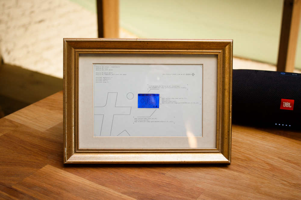
  • Build myself a simple temperature sensor with a clock. No RTC, just pulling time from controller and updating every 10 minutes to avoid drift. Also requesting outdoor temperature from controller. Build from what was lying around - DHT22, pro mini clone, nokia screen. I can share the code if someone needs it 🙂0_1542116517443_IMG_6557.jpg 0_1542116523024_IMG_6560.jpg


  • Mod

    @monte if you can share, pls do so 🙂


  • Ask questions if something is left unclear.

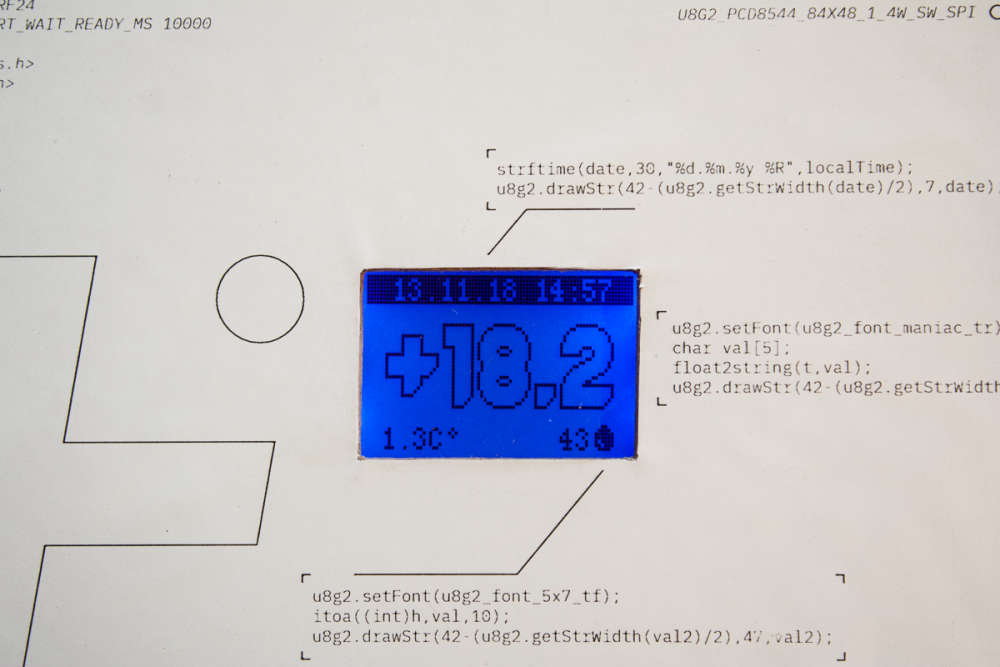
    #define DHT_PIN 4
    #define CE_DISPLAY 5
    #define RST_DISPLAY A2
    #define DC_DISPLAY A3
    #define DIN_DISPLAY 7
    #define CLK_DISPLAY 8
    #define SN "Clock + Temperature"
    #define SV "1.0"
    #define DHT_TYPE DHT22
    
    #define MY_RADIO_NRF24
    #define MY_TRANSPORT_WAIT_READY_MS 10000
    
    #include <MySensors.h>
    #include <U8g2lib.h>
    #include <DHT.h>
    #include <time.h>
    
    volatile unsigned long rawTime;
    unsigned long timer1 = 0;
    unsigned long getTimeDelay = 600000;
    unsigned long timer2 = 0;
    int getDHTDelay = 3000;
    unsigned long timer3 = 0;
    unsigned int sendDelay = 60000;
    
    float h, t;
    char outdoorTemp[50];
    float lastT;
    
    U8G2_PCD8544_84X48_1_4W_SW_SPI u8g2(U8G2_R0, /* clock=*/ CLK_DISPLAY, /* data=*/ DIN_DISPLAY, /* cs=*/ CE_DISPLAY, /* dc=*/ DC_DISPLAY, /* reset=*/ RST_DISPLAY);  // Nokia 5110 Display
    DHT dht(DHT_PIN, DHT_TYPE);
    MyMessage tempMsg(0, V_TEMP);
    volatile struct tm * localTime;
    
    void before()
    {
      u8g2.begin();
      Serial.begin(115200);
      u8g2.firstPage();
      do {
        initScreen();
      } while ( u8g2.nextPage() );
      dht.begin();
      delay(2000);
    }
    
    void setup() {
      setupTime();
      timer1 = millis();
      t = dht.readTemperature();
      h = dht.readHumidity();
      timer2 = millis();
      send(tempMsg.set(t, 0));
      lastT = t;
      timer3 = millis();
    }
    
    void presentation()
    {
      present(0, S_TEMP);
      present(1, S_INFO); //Info sensor to request outdoor tempereture
      sendSketchInfo(SN, SV);
      request(1, V_TEXT);
    }
    
    void setupTime()	//setting up timer and interrupt for seconds counter
    {
      cli();
      //set timer1 interrupt at 1Hz
      TCCR1A = 0;// set entire TCCR1A register to 0
      TCCR1B = 0;// same for TCCR1B
      TCNT1  = 0;//initialize counter value to 0
      // set compare match register for 1hz increments
      OCR1A = 15624;// = (16*10^6) / (1*1024) - 1 (must be <65536)
      // turn on CTC mode
      TCCR1B |= (1 << WGM12);
      // Set CS10 and CS12 bits for 1024 prescaler
      TCCR1B |= (1 << CS12) | (1 << CS10);
      // enable timer compare interrupt
      TIMSK1 |= (1 << OCIE1A);
      sei();
      requestTime();
    }
    
    ISR(TIMER1_COMPA_vect)
    {
      rawTime++;	//increment seconds counter
    }
    
    void float2string(float n, char* output)
    {
      char aChar[5];
      char bChar[4];
      if (n > 0.0) {
        strcpy(aChar, "+");
      } else if (n < 0.0) {
        strcpy(aChar, "-");
      }
      dtostrf(n, 4, 1, bChar);
      sprintf(output, "%s%s", aChar, bChar);
    }
    
    void initScreen()	//function to show message on screen during node start
    {
      u8g2.setFont(u8g2_font_profont12_tr);
      u8g2.drawStr(42 - (u8g2.getStrWidth("Connecting to") / 2), 13, "Connecting to");
      u8g2.drawStr(42 - (u8g2.getStrWidth("a MySensors") / 2), 26, "a MySensors");
      u8g2.drawStr(42 - (u8g2.getStrWidth("network.") / 2), 39, "network");
    }
    
    void mainScreen()
    {
      u8g2.setDrawColor(1);
      u8g2.setFontMode(1);
      u8g2.drawBox(0, 0, 84, 8);
      u8g2.setDrawColor(0);
      u8g2.setFont(u8g2_font_profont10_tf);
      localTime = localtime(&rawTime);	//using standart AVR time.h library to convert seconds counter into local time
      char date[30];
      strftime(date, 30, "%d.%m.%y %R", localTime);	//constructing a string with date and time
      u8g2.drawStr(42 - (u8g2.getStrWidth(date) / 2), 7, date);
      u8g2.setDrawColor(1);
      u8g2.setFont(u8g2_font_maniac_tr);
      char val[5];
      float2string(t, val);	//converting float value from dht11 to a string
      u8g2.drawStr(42 - (u8g2.getStrWidth(val) / 2), 36, val);
      u8g2.setFont(u8g2_font_profont10_tf);
      u8g2.drawStr(5, 47, outdoorTemp);
      itoa((int)h, val, 10); //I don't need precision for humidity procentage, otherwise you can use dtostrf()
      u8g2.drawStr(70 - u8g2.getStrWidth(val), 47, val);
      u8g2.setFont(u8g2_font_open_iconic_thing_1x_t);
      u8g2.drawStr(71, 47, "\x48");
    }
    
    boolean isTime(unsigned long *timeMark, unsigned long timeInterval)	//time counter function for non-blocking delays
    {
      if (millis() - *timeMark >= timeInterval) {
        *timeMark = millis();
        return true;
      }
      return false;
    }
    
    void loop() 
    {
      if (isTime(&timer1, getTimeDelay)) {	//request time from controller once in 10 minutes
        requestTime();
      }
      if (isTime(&timer2, getDHTDelay)) {	//polling DHT sensor and printing values to serial
        t = dht.readTemperature();
        h = dht.readHumidity();
        Serial.print("Temperature: ");
        Serial.print(t);
        Serial.println("°");
        Serial.print("Humidity: ");
        Serial.print(h);
        Serial.println("%");
      }
      if (isTime(&timer3, sendDelay)) {	//sending temperature to controller once in 30 seconds
        if (t != lastT) {
          send(tempMsg.set(t, 0));
          request(1, V_TEXT);
          lastT = t;
        }
      }
      u8g2.firstPage();	//this section is for screen handling
      do {
        mainScreen();
      } while ( u8g2.nextPage() );
    
    }
    
    void receive(const MyMessage &message)	//receiving an outdoor reading from the controller and constructing a string to display
    {
      if (message.type == V_TEXT) {
        sprintf(outdoorTemp, "%sC%s", message.getString(), "\xb0");
      }
    }
    
    void receiveTime(uint32_t ts)
    {
      rawTime = ts - UNIX_OFFSET;	//substructing an offset from received timestamp, since time.h doesn't use Unix count
      localTime = localtime(&rawTime);	//updating seconds timer with accurate value
      timer1 = millis();
    }


  • I repurposed a breakout board to make an informal range test of an RA-01 (433 Mhz).
    The test was not very sophisticated -- I had MySensors node request time from the controller and blink a LED when it received the time. Then I just walked around my neighborhood.
    Lost the signal at ~ 156 Meters. This was down hill and through several houses.
    Picked up again at ~ 248 Meters. This was at about the same elevation as my house but still through several houses.
    It also works well in the far corner of my basement (2 floors and 1 or 2 walls). The NRF24 has trouble there, but RFM69 does not.
    The range may not seem very impressive for a LoRa radio (I hoped for kilometers : ) , but the antennas are not optimized and this is a fairly dense suburban area -- difficult to get line of site. They certainly work well enough for any application I have in mind.


  • Hero Member

    @nagelc If you add some coding gain, you should be able to get longer range. However, tx time will increase.


  • Thks. I'll try that.


  • Not so much a MySensors build as an example of how even the most basic information can inform changes for the better, in this case space heating.

    The system here is fairly basic, an array of DS18B20s, some ultrasonic tank probes and a gas reed sensor, temperature is updated every 5 minutes, the gas updates every 0.05m3...
    With winters here down to -20, the first priority last year was insulation, and even though a modern house, the gas bills essentially halved over the year, effectively funding not only the insulation, but replacement axial radiator valves and thermostat heads (Heimeier) to replace the typical arrangement of unknown origin, with spare... But now the MySensors impact..
    This autumn's attention turned to the central heating unit, a modern combi unit of good manufacture, installed by a 'certified' heating engineer, but aside what little I knew about condensation boilers and the steep learning curve that followed, I was bemused by the return from the radiator loop almost burning my finger within 10 minutes of the system being fired up. This did not make sense for what I understood of a condensing boilers, which compelled a look inside for the first time, the manual and some googling.

    The boiler is a 25kW combi with minimum output 7.6kW, the radiators account for ca 13kW at Delta 60 set for 15c drop (previously set ca 20c drop), settings since day one were 65c and the pump was set at max output of 3, last year's -20 resulted in 13.5m3/day gas consumed, not crazy by historical records, but hmmm.
    So now comes tinkering with data from MySensors via Domoticz to inform...
    Currently the boiler is set at 55c, the pump is on Low (40 v 84w), but the results are surprising - Slower rising temperature when ON, 42 minutes v 25, but gas use dropped from 0.75 to 0.6m3, but here's the kicker from that longer heating time, not only less energy used per cycle, but longer and thereby fewer cycles per day. Current evaluations are between 15 and 20% savings, so thank you to all the MySensors community and contributors.. 😉


  • I have build a very quick board with Dual relay channel, arduino nano, NRF24 transceiver, Power supply from 220V.
    There is also "Fil Pilote" connection to pilot the electrical heater. It is a french protocol.
    It is a "dirty" board for sure but usefull when i want to test some code implemented in the arduino Nano.

    0_1543502852591_IMG_20181129_153704.jpg

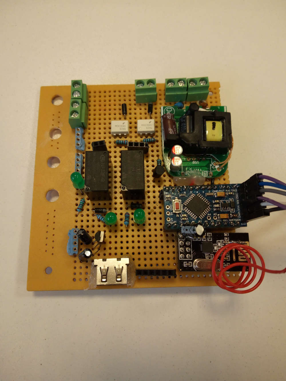
    I would like to make a cleaner board, a real PCB but if i launch the manufacturing i wil get minimum of 10 boards that i do not need.

    If anybody, could explain to me how i can print my own PCB for quick tests about some projects, some features implementations, it would be nice 🙂


  • Hero Member

    @jeremushka Well, since you ask, you can use a CNC to etch and drill your own PCB: https://forum.mysensors.org/topic/8735/cnc-pcb-milling

    A board such as yours would be fairly easy to do that way.


  • @neverdie thanks for the advice. Maybe i can first try pcb transfer with laser printer and chemical etching.


  • @jeremushka
    I have used that several times with good results, though do not make wires too narrow and put them too close to each other.


  • Mod

    @zboblamont lowering water temperature and pump speed is expected to use less energy, but have you considered the time it takes now to reach the set room temperature compared to what you had before?


  • @gohan Sorry, had to edit original post which was too confused on re-reading.
    The pump speed curves determine the pressure and flow rate to the radiators, it is the radiators which determine the actual flow for a given temperature drop across them, and speed in raising room temperatures.
    The combined flow rate for all the radiators falls within the lower pump curve, any increase in pump speed only increases pressure, NOT speed of heating.
    Aside the original mis-set HIGH rate on the pump, there are 3 manual valves left in the system, and no matter how close I try to balance them it was always a compromise, and heat inevitably goes back to the return as pressure increases
    Once these are replaced with flow control version in the next week, it will not matter what the pressure is, the radiator flows will be capped at the most efficient level.


  • My wife said "I do not want to see "those things""...
    Challenge accepted!

    0_1544224086865_TV LED display 1 - 20181207_171500.jpg

    1_1544224086867_TV LED display 2 - 20181207_183612.jpg

    0_1544224266422_MVI_5770.00_00_03_13.Still001.jpg

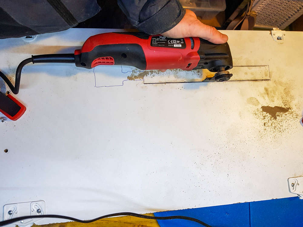
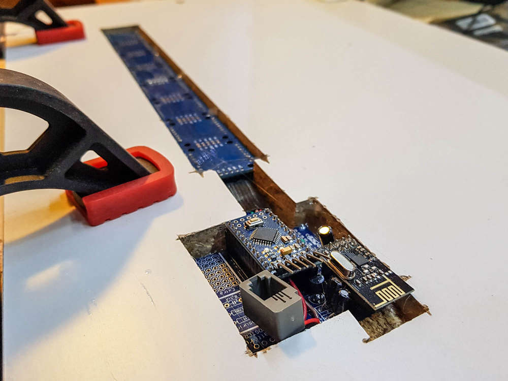
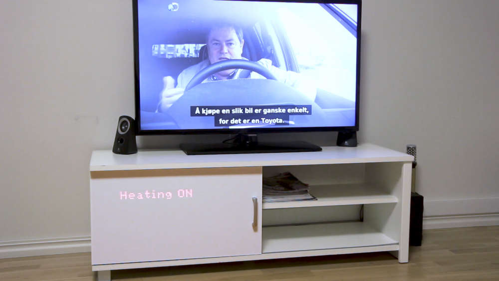
    (see the gif in action here https://ibb.co/BCbS2Dc )


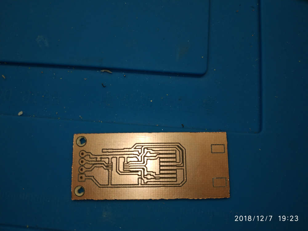
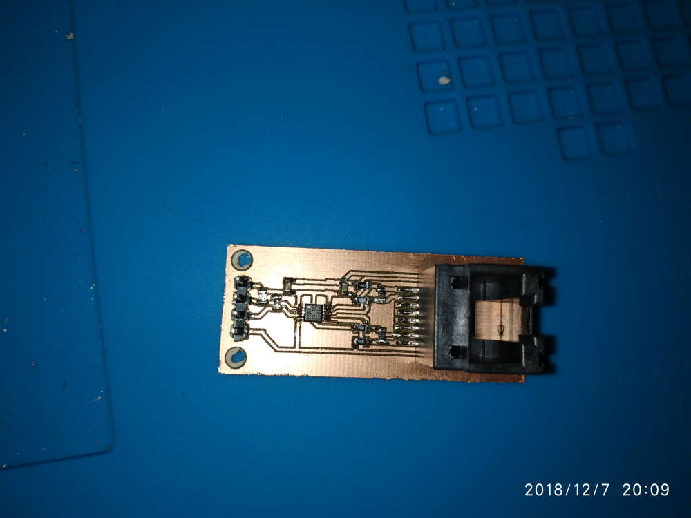
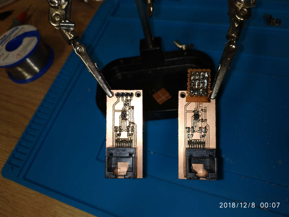
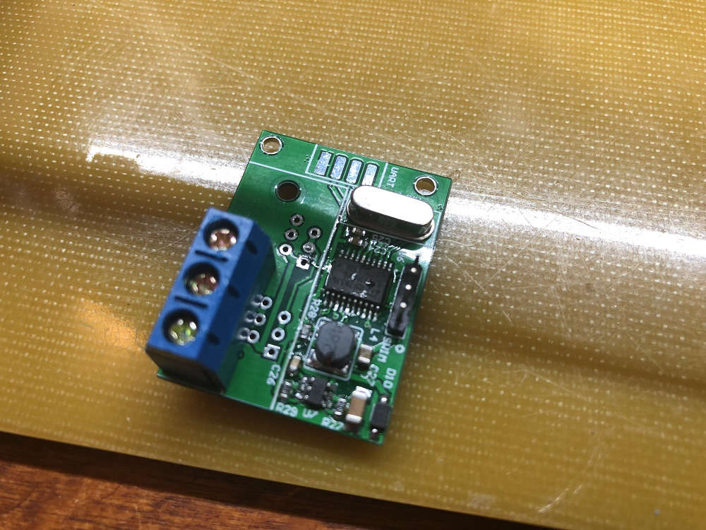
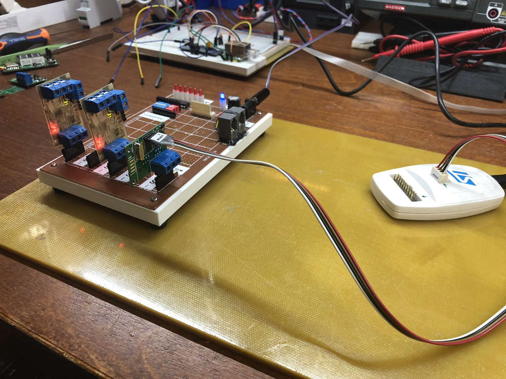
  • Milled some PCA9615 differential I2C converters for the sensors ouside: magnetometer for the gas meter, temp/hum, baro.
    Until now I've used a 7 meter long cable, but whenever the gas water heater fired up the Arduino would just freeze losing the count of gas pulses, I've tried shielded cable but it hasn't solved the issue.
    Since Sparkfun's breakout boards are on the wrong side of the pond I decided to make my own.
    Really hope the Arduino doesn't lock up anymore.

    LE. That TSSOP10 was a b*tch to solder 😁

    0_1544228821399_IMG_20181207_192354.jpg 0_1544228904350_IMG_20181207_200947.jpg 0_1544228912010_IMG_20181208_000800.jpg


  • Hardware Contributor

    @dakipro woaw!!! 👏


  • Hardware Contributor

    @dakipro thank you that's what I planned to do but wasn't sure it would be visible through the plastic layer.
    Coupled with capacitive sensors it could give awesome results !


  • @dakipro
    great job 🙂
    , and also the show on TV is quite funny, those two Englishmen in US buying old cars renovating and selling those


  • @nca78 I used white decorative self adhesive wallpaper, so not sure which plastic you are planing to use, but you can easily test that before mounting I think. If you go for paper/foil, put some one-peace plastic in front of the displays as they (mine) are not perfectly soldered in line, so they are noticeable sa foil will glue to them. Not a big deal for me, but would love "the perfection". But yeah, plastic or some harder material would work awesome I think.

    All in all, not difficult project and a very high wow-factor/time-spent value (and waf)


  • Hardware Contributor

    @dakipro ah ok you cheated 😄

    I thought you kept the plastic layer that's glued on top of the wood panel. I'll try to get some samples from the company selling those here and make some tests then.


  • @dakipro
    BTW I can only recommend to spray your bare cobber wires with Plastic 70, as this will protect your cobber from corrosion with a thin layer acrylic

    0_1544345727981_plastik_70.png


  • Try this one.
    The smallest board I have ever assembled using just a hot fan. A solar battery charger based on BQ25504 from a solar panel. Almost all components are 0402. Far too small for my liking, but can go under the solar panel.

    0_1546964306401_FFE84E8C-991D-4342-8272-2180F79333A8.jpeg


  • Looks great. I'm still happy when I get an 0805 down well. Guess I have to keep practicing.


  • Hardware Contributor

    @nagelc said in What did you build today (Pictures) ?:

    Looks great. I'm still happy when I get an 0805 down well. Guess I have to keep practicing.

    Try solder paste applied with a thin needle, and a hot air gun at minimum speed (so components don't fly away). Then it's really easy to do SMD 🙂


  • @nca78 there many other aspects. I’m using a low temp melting solder paste. I have been using only a top quality (no AliExpress) one from Chipquick. It has to be stored property in the fridge.

    Using stencil may help. I’m not using it and have to doze the paste very precisely which is a challenge. This is why my soldering is not 100% consistent, but it works. With 0402 components it is not easy - the pad size is very small.

    However, I must admit, 0402 are far too small. In the process, unless your space / lab is very well organised many components are lost. And a good magnifying glass / microscope is a must too. In the future, i’ll try to stick to 0805 or larger - these are a bit larger and more visible.

    All in all, this is not as difficult as many people may think. With a little bit of practice, this can be done.


  • @nagelc try 0603 size first. I am sure you will manage it with 0402 with a good microscope ;-))

    I’m still using a magnifying glass which is an extra challenge. Eventually I will have to buy a good microscope


  • Mod

    @alexsh1 how much did one module cost?


  • Hardware Contributor

    Today i recieved my new mini-easy-pcb i posted some info about 3 months ago. This with a breakoutboard-daugher board for all "common" sensors in the MySensors shop. I want to create a small motherboard which can be powered using a battery but also can use the battery for UPS/backup if powered from another daugherboard. The motherboard should be standard and then I would be able to add 1-2 daugherboards to specify the node.

    The breakoutboard is just for test, but can be used by newbies offcourse.
    My wish is to create the ultimate security sensor running on 12v but with a battery backup. It should include motion, temp, smoke and light.

    0_1548081587912_377d9c22-187f-4482-812f-80bb7d553bce-image.png

    0_1548081617961_8349e553-898f-4e17-b29d-87eba091e53c-image.png

    Il will get back in another 3 months when tested 😉


  • @sundberg84 Nice job.


  • @nca78
    Thanks for giving me a push. I had used hot air only for removing parts. I got some paste and populated my first board. So easy compared to the soldering iron.


  • @gohan module? you mean the PCB? or total?


  • So for some time now I have been working on a conversion to my 3D printer to allow me to change between different tool heads easily, thus increasing the versatility of the machine. To jump right in and give a little background on the mod, I have a plate that mounts to my X carriage that has 4 10mm neodymium magnets in it. These magnets hold the tool in place that will be used which also has 4 magnets in it's mounting plate.0_1549168718079_Resized_20181230_084440_8356-2.jpg
    0_1549168740823_Resized_20181230_084411_8868-2.jpg
    The first tool that I did was my 3D printer head. I obviously did that one first because I would need that to make future parts and tool heads to expand the machine. Here is my 3D printer head mounted to the working assembly.
    0_1549169544562_Resized_20190118_013816_2670.jpg
    Another tool head that I made for this is my simple pen plotter tool for drawing.
    0_1549169817834_Resized_20190202_225547_6180.jpg
    Here is a sample of something I did with the pen plotter using fine point sharpie markers. The left is the original image, and the right was done with the plotter.
    0_1549170644769_0f86124a-cf32-4e8a-a078-f2e4870df5a3-image.png
    The most recent tool head that I did was my laser engraver tool. This tool is the main reason for this post. This is the 6 watt laser module mounted to the carriage.
    0_1549170198674_Resized_20190202_230033_4069.jpg
    So what I am looking to do with this on the MySensors end of things is to build some sort of flame sensor that can monitor the engraving operation to indicate a small fire and take some sort of action, and also report it to my vera controller. Exactly what action I would have it take I have not figured out yet. If anyone has suggestions I'm all ears. I was thinking of something that could easily extinguish the small flame. As for the flame sensor, I know they make these small flame sensor modules, but I don't know how reliable they are, ore even how they work.
    0_1549171496732_6c6a2026-c4f2-408a-83a5-745076ec537d-image.png

    For anyone interested, here is a sample engraving on a piece of thin plywood. The left image is the original. The center is at a low resolution, and the right one was at a high resolution.
    0_1549172116707_f5a6f311-a35e-4363-8e9d-e4c3cb6460a6-image.png
    One other thing that I want to test with this is I've seen people that make circuit boards with these. They spray a layer or two of paint on their blank copper clad and then laser etch their pattern on the painted surface. Then they run it through their ferric chloride or other etching solution. Finally, sand off the layer of paint.

    Any suggestions or help people can give is greatly appreciated. Thanks for viewing.


  • Mod


  • @mfalkvidd Not a bad idea. I could get a CO2 canister with a solenoid valve and hook it to a hose that would blow CO2 directly onto the flame to put it out. Since my 3D printer is in an enclosure, it should contain the CO2 helping further extinguish the flame.


  • Admin

    @dbemowsk

    Cool setup, is the adapter system stable enough for the different tools? Mainly the extruder for the 3d printing?


  • @tbowmo With the 4 recessed indents on the plate, it centers the tool being mounted pretty good. I have printed a number of things with it since the upgrade and haven't had any issues with it yet. The Makerbot Replicator series of printers use a similar way of attaching their Smart Extruder heads with the 4 magnets in the corners.
    0_1549405568093_d4143092-fc52-4f28-a738-8938b2181ad4-image.png

    One difference between the Makerbot extruders and my setup is that the Makerbots put their extruder stepper behind the hot end assembly and that mates to the motor with a castle nut type assembly.
    0_1549406115458_a97a2379-85fb-4247-8c5f-dfdec50722cf-image.png

    My setup uses a Bowden extruder setup that is mounted at the top of my enclosure.
    0_1549406227269_a9f59e50-adae-484d-85e9-9d79c9eaf733-image.png
    With no stepper on my hot end, that takes the majority of the weight off of the carriage. This is one of the first tests of the 3D printer head.
    3D printing tool test – 02:09
    — Dan Bemowski


  • Admin

    @dbemowsk

    One extra question, what type of filament did you use to print the adapter plates in?


  • @tbowmo All the parts are in PETG. I got the 1kg roll cheap on Amazon for $12 US with prime shipping.


  • For anyone interested in my 3D printer mod for using different tools, I posted it on thingiverse.
    https://www.thingiverse.com/thing:3407486


  • Built a 1284(p) into a 328p Pro Mini footprint. Not sure what to call it, a Pro Mini XL maybe?

    0_1549628124362_328p Pro Mini vs. 1284p Pro Mini XL.jpg

    I now have x4 the program memory (128K vs. 32K), x4 the EEPROM (4K vs. 1K) and x8 the SRAM (16K vs. 2K) all in a 328p Pro Mini pin-compatible (I think!) footprint of about same size.

    I can also run at 20MHz vs. the usual 8MHz provided I’m prepared to run it at 4.5v and above.

    Had to sacrifice a few pins and components, but might be able to put various selections back in future revisions. Nothing major (in my opinion) just components associated with the regulator really. I also went for a crystal (not installed yet, on order, LEDs too..) over a resonator - just a personal preference for when timing is critical.

    And yes, those are 0402 SMDs. I actually did them by hand (!) with a microscope and a judicious amount of coffee; a fine-point iron, solder wick and flux became my best friends.

    So far, I’ve had it working with nRF24s and RFM69s radios, ATSHA for personalization and external flash for FOTA. The DualOptiboot bootloader code and makefile needed a bit of tweaking, but nothing major.

    I broke out the JTAG I/F but haven’t played with that yet and also added power pins next to the I2C to make some of the sensor modules (like SI7021) pluggable - see below.

    0_1549628236323_Pro Mini XL with RFM69HW ATSHA EEPROM and SI7021.jpg

    I also want to play with the QTouch library support for built-in capacitive touch buttons, sliders, etc.

    Why not just go with an ARM (STM32, SAMD, nRF52)?

    I’m working on it! ;o)

    Am not wanting to start a(nother) 8-bit vs. 32-bit discussion. I’ve got an AliExpress package of 32-bit MCUs coming (very) slowly to me. When it arrives, I’ll start experimenting and exploring - probably with the nRF52s, since those seem to be the flavor-of-the-month and very capable-looking chips...

    But until then, I need more program memory!
    (Among other things…)


  • Finally finished building my dual precision voltage reference LTC6655:

    0_1549896394457_B2F58A87-E2DB-436B-ADFA-0514F43D2AAA.jpeg


  • @acb I have built similar board.
    0_1549896894038_41B5EC1D-BA6B-4ADA-BE5D-9CB48359207D.jpeg

    The only downside is the cost and size of Atmega1284p is just so prohibitive. Yet it is 8 bits processor. I have only one fully conpleted board and a few blank pcbs.


  • That looks awesome @alexsh1!

    Nicely laid out and cleanly soldered. Was that with an iron or hot air (or both)? Nice clear silk too; I like the power and “signal” symbols. Did you ever try a FOTA update with it? Or a low power/speed profile?

    I see you went a bit wider and longer than the standard Pro Mini, (I’m assuming) to get at all the pins and add the extra regulator, LEDs, etc.

    I was constrained by needing something that fit the same footprint for existing boards I already had, e.g. other “motherboards” I’d made similar to @sundberg84’s excellent Easy/Newbie PCB or wanting pin-compatibility for stacking boards like the ATSHA+EEPROM+Radio+ICSP one below:

    0_1549963211745_06 - Pro Minis with ATSHA, Ext. Flash, Radio & ICSP.jpg

    I tried routing with the chip at a 45 degree angle too but couldn’t get a DRC to pass with the pads so close to the PTHs. I may try again with shorter (custom) TQFP pads...

    Re: 1284p’s downsides of cost and size.

    I know. I ended up justifying it to myself this way:

    We can all get cheap 328p Pro Minis from Ali for around $2. The vast majority of my Pro Mini projects are battery powered, so there’s some “labor cost” to disable the power LED and remove the regulator. But regardless, I certainly can’t make myself a low(er) power Pro Mini for $2 - the OSH Park PCB alone is probably close to that.

    I think the cheapest I ever got 1284p chips for was around $2.50, again from Ali. My “Pro Mini XL” PCBs were around $1.70 from OSH Park, add a sprinkling of 0402s, etc. and we’re probably at around $5.

    I couldn’t find any 1284p-based boards near that price. The closest I got was Kevin’s Mini Duino, which is another lovely looking board, but doesn’t fit my need for a Pro Mini-constrained size and pin-compatibility. Essentially, I was after something close to a drop-in replacement.

    So, $2+ versus $5+ for all the benefits (at least as far as I was concerned) listed above? It became a bit of a no-brainer.

    And on the low power front, I profiled the MySensors library sleep command on it at around 5uA on 4.5v @ 20MHz using an external full swing, around 4uA on 3v @ 8MHz and around 3uA on 1.8v @ 1MHz Internal RC Osc:

    0_1549963330901_03 - 3.2uA in Power-save Mode - ATMEGA 1284 on 1.8v at 1MHz Int. RC Osc.JPG

    Those numbers are certainly good enough for all my current applications - no pun intended! 😉

    But I would like to look at the 32-bit contenders as potential replacements.

    I’ve seen nRF52s with 512K for around $2 on Ali, so maybe I’ll try my hand at a Pro Mini nRF52 or something similar eventually. The board above was a fun challenge, and afterall is what this is (mainly) about for me.


  • @acb Nice pro mini sized 1284 boards. These would work nice in my in-wall OLED scene controller boards. The standard 328 pro minis really limit what I can do with the OLED display when using it with the MySensors library. I could get more use out of the graphics end of the display with something like that.

    Do you have these on OpenHardware.io? Can fully functional boards be purchased somewhere? I would be interested in trying a few out if possible.

    Kudos on the design.


  • Thanks for the kudos, @dbemowsk. Right back at you for your scene controllers; I’m trying to get into 3D design myself, but can’t justify the time commitment right now.

    Re: Do you have these on OpenHardware.io?

    No, sorry, that would require me to be far more organized than I am at present! 😉

    Maybe if there was enough interest, I could justify putting in the time to clean things up enough to publish… But it is valentines today, so any tinkering will surely be met with an icy stare if I try it tonight! 😮

    Re: Can fully functional boards be purchased somewhere? I would be interested in trying a few out if possible.

    Really? I’ve never done something like that before. You do realize these are very much “alpha” right? I mean, I’ve tested the majority of the pins, but nothing like proper production hardware verification or anything. Having said that, it’s not like there’s anything complicated going on.

    I managed to dig out four spares this afternoon that I’m not using from the last batch I made - how many would you like?

    0_1550175379519_07 - 4x Pro Mini XLs.JPG

    Three have a 1284p attached and one has the regular 1284 - I believe the only difference is the 1284 doesn’t have BOD, but I normally turn that off anyway for a (probably) miniscule power saving. I haven’t installed the crystal oscillator or reset switch yet. I don’t normally do that until I know what the use-case is. I believe I have enough spare 16MHz and 20MHz ones to fit (maybe some 8s) and some SMD reset switches too.

    The only other thing would be the bootloader. I could flash the standard MySensors DualOptiboot?

    So, if you (or I suppose anyone else for that matter) are interested, just shoot me a chat message via my profile and we can figure things out off-thread, as this is a bit off-topic now.

    Thanks again for the interest - even if you don’t buy - made my day! 🙂


  • Hardware Contributor

    Some photos of my new device - MDMSPanel "Nextion". I have finished soldering an hour ago)) Next week i will public this project.

    0_1550219059331_NextionPanel_1.jpg 0_1550219064537_NextionPanel_2.jpg 0_1550219068735_NextionPanel_3.jpg 0_1550219072239_NextionPanel_4.jpg 0_1550219076119_NextionPanel_5.jpg 0_1550219079784_NextionPanel_6.jpg 0_1550219083264_NextionPanel_7.jpg


  • @kalina
    Looks good, however due to EMC I strongly recommend to add a GND groundplane on your PCB. I would myself have TOP layer as +DC and BOT layer as GND, this provide less power "sparks" on the tracks and a "capacitor" effect on whole PCB

    https://en.wikipedia.org/wiki/Ground_plane#/media/File:TerraTec_G3_circuit_board_2.jpg

    https://www.quora.com/What-is-the-importance-of-a-ground-plane-of-a-PCB?share=1


  • Mod

    @kalina very cool board. Must be your most advanced MySensors board so far?


  • Hardware Contributor

    @mfalkvidd I would to say what this board is the most necessary for me at the moment. I tired of using various gadgets as a control panels for my nodes. Also, i want to try RS-485 in conjunction with MySensors. Next step is add RS-485 to my MDMSGate....


  • @bjacobse to do proper ground and vcc planes you need a 4-layer PCB. Otherwise you won't get much of a difference in terms of EMI. Another way is to have 2 layer board and to have one layer only for ground plane, but that means you have to do all routing on one side, without making lines across your ground plane. Otherwise you decreasing grounding effect on EMI.
    More on this topic in this free webinar: https://www.signalintegrityjournal.com/events/54-best-iot-board-design-practices-balancing-density-cost-low-power-and-mixed-signal


  • @monte
    Well now Kalina already uses 2 layer PCB, so to improve current 2-layer PCB with ground planes are strongly advised.
    Yes 4 layer is naturally much better, but is it needed for a "commodity" device? I think not, and it will increase PCB cost...

    If you don't have a GND and power planes, you will most likely have power spikes when an IC needs current, this will introduce a magnetic field that will "disturb" especially sensitive analogue tracks and clock signals


  • Hardware Contributor

    My actual project is a doorbell sensor with additional temperature and humidity sensors. Tried different ways to detect the ring:

    • hall sensor (failed)
    • microphone (FFT, ongoing research)
    • optocoupler to detect the 12V AC -> favorite solution

    As I was heavy prototyping, I tried wire wrapping and it is fun:
    0_1550390000040_SUNP0002_Moment.jpg


  • @acb Hot air has been used for soldering the board. I have not tried low power as I did not build this board for a battery sensor. My board has got two LEDs - power and another LED connected to D0 so clearly not very low power. I also have a 16Mhz firmware. I did not have any size limitation either. I have one particular node with a few sensors and with signing I cannot upload the sketch onto ATMEGA328P as it is marginally larger. Having said that I have not spent too much time optimising the sketch. I think that refactoring libraries, you are fine with ATMEGA328P in 98% of all MySensors applications.
    BTW - this is not my project. I have followed it https://github.com/peekpt/mightyduino

    Re cost. I stopped Ali shopping for ICs and other sensitive components some time ago after purchasing some fake ATMEGA328P and wasting so many hours trying to troubleshoot it. There is a post about it here on MySensors forum. Ever since I order all components on digi-key. 1284p is priced around $5 + 20% VAT. 328P is priced at $1.2 + VAT. However, I can also buy ATSAMD21 for $2.2 + VAT. Do you see my point? 1284p is extremely expensive and yet it is still 8 bit processor. That's why for me it was a one-off board.

    Re sleeping
    I am using TPL5110 which I built myself (similar to Adafruit one).
    Check out sleeping current:

    alt text

    Sadly, I struggled to get some sensors to sleep properly - probably lack of my programming skills - and with a sleeping current being hundreds of uA, I had to resort to this trick. Most of the time, the node sleeps is disconnected from power by TPL5110 then timer is up and it powers up, sends all sensors readings to the GW and then power gets disconnected to the node, only TPL5110 goes to nA sleep. Perfect!


  • @kalina scene controller? I have almost finished mine on Nextion, but do not have time to tidy things up.


  • Hardware Contributor

    @alexsh1 Yes, it will be a scene controller. I also developed nice enclosure with a magnetic mount. In a few days I will share new photos.


  • @bjacobse but it actually seems that he HAS a ground plane on one side of PCB, if you look closer at the third photo 😉


  • @monte I didn't notice this, but you are right, "hidden" LCD 🙂


  • @fotofieber
    Wirewrapping is an "old" and well proven technology, remember to have extra cable in case you need to re-wire your cables. Not so popular by DIY as tools used to be fairly expensive as it was protected by patents...


Log in to reply
 

Suggested Topics

  • 4
  • 2
  • 5
  • 14
  • 1
  • 9

20
Online

11.2k
Users

11.1k
Topics

112.5k
Posts