ds18b20 on 2xAAA battery
-
@nagelc,
you AA batteries must be 1.6 or above voltage, as mine had same voltage, in other words when new batteries were supplying 1.6v/AAA it was working fine as soon as voltage dropped to 3.0 temperature sensors stoped, node is sending battery voltage which mean node and radio working fine but ds18b20 stopped. -
@zboblamont, i love your analogy about ash-try in car.
i just feed arduino with 1mhz bootloader through raw pin with 2xAAA batteries (i know it was very long shot) and it didnt work onboard regulator can not supply enough voltage to ds18b20, but sure i need to look into boost converter.
before i dive into boost convert i wanted to ask what others are doing and how they are managing voltage for voltage hungry sensors. i have found few examples on openhardware.io all of them are by @NeverDie@pihome
said in ds18b20 on 2xAAA battery:i wanted to ask what others are doing and how they are managing voltage for voltage hungry sensors
One useful "switch" you have got on your PRO MINI.
My from ebay has got LDO marked LG33, which is MIC5219 LDO with shutdown pin capability.
So remove one from arduino hacked for ultra low consumption and use it for switch power hungry sensors.Or only unsolder and bend up from pcb output and shutdown pin of LDO.
Then you can use 3AAA to power directly VCC ( 4.5V ). Connect this to RAW pin ( input LDO ) too.
Your sensors connect to unsoldered LDO output pin and shutdown pin connect with some output IO to drive your sensors ON/OFF.
Problem can be, that sensors run on 3.3V and your Arduino runs on 4.5V.
So you can put some diodes in series between battery and Vcc pin. Each diode ( not LED ) drops about 0.6V ( try different diodes ).
Another interesting idea with this LDO can be seen here: -
so far i have temperature sensors running on 18650 battery by feeding to raw pin on arduino and it works fine now i'm switching to 2xAAA battery and at this stage i think i have no option but to go for boost converter to power sensor on the node, i wish i had space in sensor box i m using for 3xAAA batteries.
MIC5219-3.3BM5 is good option but it has minimum Input Voltage 2.5v, with good Quiescent 8µA but i think i m leaning toward TPS613221A boost convert chip i know it does not have shutdown option but very low quiescent current of 6.5uA, here is unfinished prototype pcb design.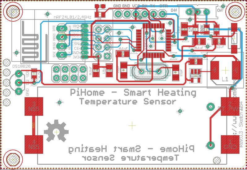
PiHome - Smart Heating Control
-
so far i have temperature sensors running on 18650 battery by feeding to raw pin on arduino and it works fine now i'm switching to 2xAAA battery and at this stage i think i have no option but to go for boost converter to power sensor on the node, i wish i had space in sensor box i m using for 3xAAA batteries.
MIC5219-3.3BM5 is good option but it has minimum Input Voltage 2.5v, with good Quiescent 8µA but i think i m leaning toward TPS613221A boost convert chip i know it does not have shutdown option but very low quiescent current of 6.5uA, here is unfinished prototype pcb design.@pihome Surely VR shutdown is irrelevant for a live device, or am I completely misunderstanding this function?
Presumably you will deploy one of these for each zone instead instead of running a cable.
Passing thought - Have you considered a plastic type battery holder on back of the circuitry, halving the current board area but making it slightly thicker? -
@zboblamont
you are right one battery powered sensor for each zone and reading once every minute and no cables to sensors. but during sleep time VR will consume power, i had thought about 3x AAA battery on the back of pcb but i n using tht nrf or perhaps i have to rethink the whole design.PiHome - Smart Heating Control
-
@zboblamont
you are right one battery powered sensor for each zone and reading once every minute and no cables to sensors. but during sleep time VR will consume power, i had thought about 3x AAA battery on the back of pcb but i n using tht nrf or perhaps i have to rethink the whole design.@pihome Perhaps re-evaluate what you are trying to achieve and how?
The array in my place reads every 5 minutes over a cable array, even for outside temperatures half-hourly samples would probably be fine, this is my screen-shot.
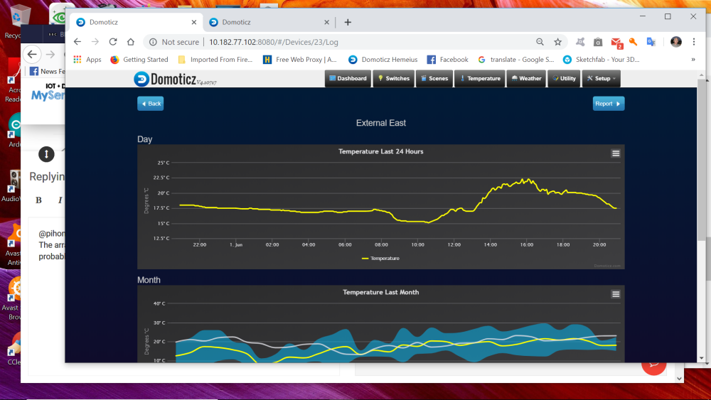
Frankly your goal of 1 minute granularity makes no sense with real world temperature variations, even in interior spaces. If the objective is heating control, room effects are slow.
If necessay you could up the sample rate when heat is circulating, thence minimise wasted yet finite energy?
Even the choice of radio may be inappropriate to your energy efficiency goals, I explained previously how this end works, @nagelc has outlined he is getting super performance with 2+ years battery life, this perhaps merits review... -
Hi All,
i have nodes running on 18650 battery on Arduino mini pro 8mhz (3.3v) without much modification or any low power bootloader but now i want to switch to AAA battery to keep everything tidy and need but one issue ds18b20 requires 3.3v whereas 2xAAA can supply 3v, now million dollar question is what you guys doing to supply 3.3v to ds18b20? boost converter consume power as well and all on ebay/aliexpress ones are seems very power hungry (Quiescent current 13uA).
https://www.aliexpress.com/item/32800430445.html?spm=2114.search0104.3.219.5b3d1a25h7pRRv&ws_ab_test=searchweb0_0%2Csearchweb201602_2_10065_10068_319_10059_10884_317_10887_10696_321_322_10084_453_10083_454_10103_10618_10304_10307_10820_10821_537_10302_536%2Csearchweb201603_51%2CppcSwitch_0&algo_expid=e6ec65d0-b780-4c66-b06a-52134fa6c454-31&algo_pvid=e6ec65d0-b780-4c66-b06a-52134fa6c454&transAbTest=ae803_3
i m thinking to find alternate to ds18b20 that can run reliably on 2v,
any thoughts or suggestions? -
i must admit you are lucky or your sensors dont care about voltage but at this stage after reading your comments i have tried 3 different sensors and all the same result
may be something is in my sketch ?
//  _____    _   _    _
// |  __ \  (_) | |  | |
// | |__) |  _  | |__| |   ___    _ __ ___     ___
// |  ___/  | | |  __  |  / _ \  | |_  \_ \   / _ \
// | |      | | | |  | | | (_) | | | | | | | |  __/
// |_|      |_| |_|  |_|  \___/  |_| |_| |_|  \___|
//
//    S M A R T   H E A T I N G   C O N T R O L
// *****************************************************************
// *       Battery Powered OneWire DS18B20 Temperature Sensor      *
// *           Version 0.31 Build Date 06/11/2017                  *
// *            Last Modification Date 09/05/2019                  *
// *                                          Have Fun - PiHome.eu *
// *****************************************************************

// Enable debug prints to serial monitor
//#define MY_DEBUG

// Enable and select radio type attached
#define MY_RADIO_RF24
//#define MY_RADIO_NRF5_ESB
//#define MY_RADIO_RFM69
//#define MY_RADIO_RFM95

// Set LOW transmit power level as default, if you have an amplified NRF-module and
// power your radio separately with a good regulator you can turn up PA level.
// #define MY_RF24_PA_LEVEL RF24_PA_LOW
// RF24_PA_MIN RF24_PA_LOW RF24_PA_HIGH RF24_PA_MAX RF24_PA_ERROR

#define MY_RF24_PA_LEVEL RF24_PA_MIN
//#define MY_DEBUG_VERBOSE_RF24

// RF channel for the sensor net, 0-127 Default is 76
#define MY_RF24_CHANNEL	76

//PiHome - Make Sure you change Node ID, for each temperature sensor. 21 for Ground Floor, 20 for First Floor, 30 for Domastic Hot Water.
#define MY_NODE_ID 33

//RF24_250KBPS for 250kbs, RF24_1MBPS for 1Mbps, or RF24_2MBPS for 2Mbps
#define RF24_DATARATE 	   RF24_250KBPS

// Set baud rate to same as optibot
//#define MY_BAUD_RATE 9600

//set how long to wait for transport ready in milliseconds
//#define MY_TRANSPORT_WAIT_READY_MS 3000


//#include <SPI.h>
#include <MySensors.h>
#include <DallasTemperature.h>
#include <OneWire.h>

#define ledpin 4 // LED for one Blink Power On, Solid LED for No sensors, 5 Blinks for no Radio (this settings is in MySensors.cpp) and three blinks for low battery

// Define sensor node childs
#define CHILD_ID_BATT 1
#define CHILD_ID_TEMP 0

#define COMPARE_TEMP 1 // Send temperature only if changed? 1 = Yes 0 = No
#define COMPARE_BVOLT 1 // Send battery voltage only if changed? 1 = Yes 0 = No
#define ONE_WIRE_BUS 3 // Pin where dallase sensor is connected

#define MAX_ATTACHED_DS18B20 2
unsigned long SLEEP_TIME = 56000; // Sleep time between reads (in milliseconds)

// Battery related init
int BATTERY_SENSE_PIN = A0;  // select the input pin for the battery sense point
float oldBatteryV = 0;
MyMessage msgBatt(CHILD_ID_BATT, V_VOLTAGE);

// Dallas Temperature related init
OneWire oneWire(ONE_WIRE_BUS); // Setup a oneWire instance to communicate with any OneWire devices (not just Maxim/Dallas temperature ICs)
DallasTemperature sensors(&oneWire); // Pass the oneWire reference to Dallas Temperature.
float lastTemperature[MAX_ATTACHED_DS18B20];
int numSensors=0;
bool receivedConfig = false;
bool metric = true;
// Initialize temperature message
MyMessage msg(CHILD_ID_TEMP, V_TEMP);

void before(){
  // Startup up the OneWire library
  sensors.begin();
}

void setup(){

	//This is LED pin set to output and turn it on for short while
	pinMode(ledpin, OUTPUT);
	digitalWrite(ledpin, HIGH);
	delay(60);
	digitalWrite(ledpin, LOW);

	// requestTemperatures() will not block current thread
  sensors.setWaitForConversion(false);
  // needed for battery soc
  // use the 1.1 V internal reference
  #if defined(__AVR_ATmega2560__)
      analogReference(INTERNAL1V1);
  #else
      analogReference(INTERNAL);
  #endif

    // disable ADC
  //ADCSRA = 0;
  //power_usart0_disable();// Serial (USART)
  //power_adc_disable(); // ADC converter
  //power_twi_enable(); // TWI (I2C)
}

void presentation() {
	// Send the sketch version information to the gateway and Controller
	sendSketchInfo("Temperature Sensor", "0.31");
	// Fetch the number of attached temperature sensors
	numSensors = sensors.getDeviceCount();
	//Blink LED as number of sensors attached
	blink_led(numSensors, ledpin);

	//check if attached sensors number is grater then 0 if no then put led on solid
	#if numSensors > 0
		digitalWrite(ledpin, HIGH);
	#else
		digitalWrite(ledpin, LOW);
	#endif


  // Present all sensors to controller
  for (int i=0; i<numSensors && i<MAX_ATTACHED_DS18B20; i++) {
     present(i, S_TEMP);
  }
}

void loop(){
	// get the battery Voltage
	//ref http://www.ohmslawcalculator.com/voltage-divider-calculator
	// Sense point is bypassed with 0.1 uF cap to reduce noise at that point

	// 1M, 100K divider across battery and using internal ADC ref of 1.1V
	// ((1e6+100e3)/100e3)*1.1 = Vmax = 12.1 Volts
	// 12.1/1023 = Volts per bit = 0.011828

	//R1 820k, R2 220k
	//((820e3+220e3)/220e3)*1.1 = Vmax = 5.2 Volts
	//5.2/1023 = Volts per bit = 0.005083089

	int battSensorValue = analogRead(BATTERY_SENSE_PIN);
	//float batteryV  = battSensorValue * 0.005083089; //R1 820k, R2 220k divider across battery and using internal ADC ref of 1.1v
	float batteryV  = battSensorValue * 0.011828;    //R1 1M, R2 100K divider across battery and using internal ADC ref of 1.1v

	//int batteryPcnt = ( ( batteryV - 2.9 ) / ( ( 4.2 - 2.9 ) / 100 ) ); // for 18650 Battery Powred
	int batteryPcnt = ( ( batteryV - 2.1 ) / ( ( 3.0 - 2.1 ) / 100 ) ); // for AAA Battery Powered


	#ifdef MY_DEBUG
		Serial.print("Pin Reading: ");
		Serial.println(battSensorValue);
		Serial.print("Battery Voltage: ");
		Serial.print(batteryV);
		Serial.println(" v");
		//Print Battery Percentage
		Serial.print("Battery percent: ");
		Serial.print(batteryPcnt);
		Serial.println(" %");
	#endif

	#if COMPARE_BVOLT == 1
		if (oldBatteryV != batteryV) {
			send(msgBatt.set(batteryV, 2));
			sendBatteryLevel(batteryPcnt);
			oldBatteryV = batteryV;
		}
	#else
		send(msgBatt.set(batteryV, 2));
		sendBatteryLevel(batteryPcnt);
		oldBatteryV = batteryV;
	#endif

	// Fetch temperatures from Dallas sensors
	sensors.requestTemperatures();
	// query conversion time and sleep until conversion completed
	int16_t conversionTime = sensors.millisToWaitForConversion(sensors.getResolution());
	//sleep() call can be replaced by wait() call if node need to process incoming messages (or if node is repeater)
	sleep(conversionTime);
  // Read temperatures and send them to controller
	for (int i=0; i<numSensors && i<MAX_ATTACHED_DS18B20; i++) {
		// Fetch and round temperature to one decimal
		float temperature = static_cast<float>(static_cast<int>((getControllerConfig().isMetric?sensors.getTempCByIndex(i):sensors.getTempFByIndex(i)) * 10.)) / 10.;
		// Only send data if temperature has changed and no error
		#if COMPARE_TEMP == 1
			if (lastTemperature[i] != temperature && temperature != -127.00 && temperature != 85.00) {
		#else
			if (temperature != -127.00 && temperature != 85.00) {
		#endif
			// Send in the new temperature
			send(msg.setSensor(i).set(temperature,1));
			// Save new temperatures for next compare
			lastTemperature[i]=temperature;
			}
		}
		//Condition to check battery levell is lower then minimum then blink led 3 times
		//if (batteryV < 2.9) { //for 18650 Battery Powered Sensor
		if (batteryV < 2.0) { //for AAA Battery Powered Sensor
			blink_led(3, ledpin);
			//Serial.print("Low Voltage");
		}
	//go to sleep for while
	//smartSleep(SLEEP_TIME);
	sleep(SLEEP_TIME);
	}

//Blink LED function, pass ping number and number of blinks usage: blink_led(variable or number of time blink, ledpin);
void blink_led(int count, int pin){
	for(int i=0;i<count;i++){
		digitalWrite(pin, HIGH);
		delay(700);
		digitalWrite(pin, LOW);
		delay(700);
	}
}
PiHome - Smart Heating Control
-
i must admit you are lucky or your sensors dont care about voltage but at this stage after reading your comments i have tried 3 different sensors and all the same result
may be something is in my sketch ?
// _____ _ _ _ // | __ \ (_) | | | | // | |__) | _ | |__| | ___ _ __ ___ ___ // | ___/ | | | __ | / _ \ | |_ \_ \ / _ \ // | | | | | | | | | (_) | | | | | | | | __/ // |_| |_| |_| |_| \___/ |_| |_| |_| \___| // // S M A R T H E A T I N G C O N T R O L // ***************************************************************** // * Battery Powered OneWire DS18B20 Temperature Sensor * // * Version 0.31 Build Date 06/11/2017 * // * Last Modification Date 09/05/2019 * // * Have Fun - PiHome.eu * // ***************************************************************** // Enable debug prints to serial monitor //#define MY_DEBUG // Enable and select radio type attached #define MY_RADIO_RF24 //#define MY_RADIO_NRF5_ESB //#define MY_RADIO_RFM69 //#define MY_RADIO_RFM95 // Set LOW transmit power level as default, if you have an amplified NRF-module and // power your radio separately with a good regulator you can turn up PA level. // #define MY_RF24_PA_LEVEL RF24_PA_LOW // RF24_PA_MIN RF24_PA_LOW RF24_PA_HIGH RF24_PA_MAX RF24_PA_ERROR #define MY_RF24_PA_LEVEL RF24_PA_MIN //#define MY_DEBUG_VERBOSE_RF24 // RF channel for the sensor net, 0-127 Default is 76 #define MY_RF24_CHANNEL 76 //PiHome - Make Sure you change Node ID, for each temperature sensor. 21 for Ground Floor, 20 for First Floor, 30 for Domastic Hot Water. #define MY_NODE_ID 33 //RF24_250KBPS for 250kbs, RF24_1MBPS for 1Mbps, or RF24_2MBPS for 2Mbps #define RF24_DATARATE RF24_250KBPS // Set baud rate to same as optibot //#define MY_BAUD_RATE 9600 //set how long to wait for transport ready in milliseconds //#define MY_TRANSPORT_WAIT_READY_MS 3000 //#include <SPI.h> #include <MySensors.h> #include <DallasTemperature.h> #include <OneWire.h> #define ledpin 4 // LED for one Blink Power On, Solid LED for No sensors, 5 Blinks for no Radio (this settings is in MySensors.cpp) and three blinks for low battery // Define sensor node childs #define CHILD_ID_BATT 1 #define CHILD_ID_TEMP 0 #define COMPARE_TEMP 1 // Send temperature only if changed? 1 = Yes 0 = No #define COMPARE_BVOLT 1 // Send battery voltage only if changed? 1 = Yes 0 = No #define ONE_WIRE_BUS 3 // Pin where dallase sensor is connected #define MAX_ATTACHED_DS18B20 2 unsigned long SLEEP_TIME = 56000; // Sleep time between reads (in milliseconds) // Battery related init int BATTERY_SENSE_PIN = A0; // select the input pin for the battery sense point float oldBatteryV = 0; MyMessage msgBatt(CHILD_ID_BATT, V_VOLTAGE); // Dallas Temperature related init OneWire oneWire(ONE_WIRE_BUS); // Setup a oneWire instance to communicate with any OneWire devices (not just Maxim/Dallas temperature ICs) DallasTemperature sensors(&oneWire); // Pass the oneWire reference to Dallas Temperature. float lastTemperature[MAX_ATTACHED_DS18B20]; int numSensors=0; bool receivedConfig = false; bool metric = true; // Initialize temperature message MyMessage msg(CHILD_ID_TEMP, V_TEMP); void before(){ // Startup up the OneWire library sensors.begin(); } void setup(){ //This is LED pin set to output and turn it on for short while pinMode(ledpin, OUTPUT); digitalWrite(ledpin, HIGH); delay(60); digitalWrite(ledpin, LOW); // requestTemperatures() will not block current thread sensors.setWaitForConversion(false); // needed for battery soc // use the 1.1 V internal reference #if defined(__AVR_ATmega2560__) analogReference(INTERNAL1V1); #else analogReference(INTERNAL); #endif // disable ADC //ADCSRA = 0; //power_usart0_disable();// Serial (USART) //power_adc_disable(); // ADC converter //power_twi_enable(); // TWI (I2C) } void presentation() { // Send the sketch version information to the gateway and Controller sendSketchInfo("Temperature Sensor", "0.31"); // Fetch the number of attached temperature sensors numSensors = sensors.getDeviceCount(); //Blink LED as number of sensors attached blink_led(numSensors, ledpin); //check if attached sensors number is grater then 0 if no then put led on solid #if numSensors > 0 digitalWrite(ledpin, HIGH); #else digitalWrite(ledpin, LOW); #endif // Present all sensors to controller for (int i=0; i<numSensors && i<MAX_ATTACHED_DS18B20; i++) { present(i, S_TEMP); } } void loop(){ // get the battery Voltage //ref http://www.ohmslawcalculator.com/voltage-divider-calculator // Sense point is bypassed with 0.1 uF cap to reduce noise at that point // 1M, 100K divider across battery and using internal ADC ref of 1.1V // ((1e6+100e3)/100e3)*1.1 = Vmax = 12.1 Volts // 12.1/1023 = Volts per bit = 0.011828 //R1 820k, R2 220k //((820e3+220e3)/220e3)*1.1 = Vmax = 5.2 Volts //5.2/1023 = Volts per bit = 0.005083089 int battSensorValue = analogRead(BATTERY_SENSE_PIN); //float batteryV = battSensorValue * 0.005083089; //R1 820k, R2 220k divider across battery and using internal ADC ref of 1.1v float batteryV = battSensorValue * 0.011828; //R1 1M, R2 100K divider across battery and using internal ADC ref of 1.1v //int batteryPcnt = ( ( batteryV - 2.9 ) / ( ( 4.2 - 2.9 ) / 100 ) ); // for 18650 Battery Powred int batteryPcnt = ( ( batteryV - 2.1 ) / ( ( 3.0 - 2.1 ) / 100 ) ); // for AAA Battery Powered #ifdef MY_DEBUG Serial.print("Pin Reading: "); Serial.println(battSensorValue); Serial.print("Battery Voltage: "); Serial.print(batteryV); Serial.println(" v"); //Print Battery Percentage Serial.print("Battery percent: "); Serial.print(batteryPcnt); Serial.println(" %"); #endif #if COMPARE_BVOLT == 1 if (oldBatteryV != batteryV) { send(msgBatt.set(batteryV, 2)); sendBatteryLevel(batteryPcnt); oldBatteryV = batteryV; } #else send(msgBatt.set(batteryV, 2)); sendBatteryLevel(batteryPcnt); oldBatteryV = batteryV; #endif // Fetch temperatures from Dallas sensors sensors.requestTemperatures(); // query conversion time and sleep until conversion completed int16_t conversionTime = sensors.millisToWaitForConversion(sensors.getResolution()); //sleep() call can be replaced by wait() call if node need to process incoming messages (or if node is repeater) sleep(conversionTime); // Read temperatures and send them to controller for (int i=0; i<numSensors && i<MAX_ATTACHED_DS18B20; i++) { // Fetch and round temperature to one decimal float temperature = static_cast<float>(static_cast<int>((getControllerConfig().isMetric?sensors.getTempCByIndex(i):sensors.getTempFByIndex(i)) * 10.)) / 10.; // Only send data if temperature has changed and no error #if COMPARE_TEMP == 1 if (lastTemperature[i] != temperature && temperature != -127.00 && temperature != 85.00) { #else if (temperature != -127.00 && temperature != 85.00) { #endif // Send in the new temperature send(msg.setSensor(i).set(temperature,1)); // Save new temperatures for next compare lastTemperature[i]=temperature; } } //Condition to check battery levell is lower then minimum then blink led 3 times //if (batteryV < 2.9) { //for 18650 Battery Powered Sensor if (batteryV < 2.0) { //for AAA Battery Powered Sensor blink_led(3, ledpin); //Serial.print("Low Voltage"); } //go to sleep for while //smartSleep(SLEEP_TIME); sleep(SLEEP_TIME); } //Blink LED function, pass ping number and number of blinks usage: blink_led(variable or number of time blink, ledpin); void blink_led(int count, int pin){ for(int i=0;i<count;i++){ digitalWrite(pin, HIGH); delay(700); digitalWrite(pin, LOW); delay(700); } }@pihome Not sure why you are looking for a sketch problem if the issues don't arise >=3v?
That some folks have ds18b20 working below the specified minimum of 3v is pure luck, but even were you to source devices which could work down to say 2.8v, it still does not address their certain disfunction below it, particularly down to the 1.9v drop off voltage of your radio, which was your objective?
Your options are limited to swapping to a sensor (?) which works down to 1.9v, switch on/off a separate supply for the ds18b20, or run a full-time booster for the entire assembly to suck all life from your batteries. It is this latter scenario here, but designed and built by folks clever than I.
Very tempted after this to look at switching on/off the ds18b20 array's power and see how long it lasts on batteries aloe, perhaps a rainy day or winter project. -
@zboblamont,
yes you are right it is pure luck, i just wanted to check i m not doing anything stupid and said pair of eyes are always good. i have ordered the parts and i m going to work on two version: one with boost convert for sensor and second 3xAAA with voltage regulator and probably 3rd version (may be in future when i get some free time) with boost converter with shutdown, may be some one already have done this and my search string isnt very good to dig that out. -
further update:
while playing with 1mhz bootloader and feeding arduino to raw pin from 18650 battery, sensors is successfully sending battery voltage and battery percentage but no temperature sensor reading. to prove that something isnt right with 1mhz bootloader i burned 8mhz default bootloader i get battery voltage, battery percentage and temperature reading. can not think of something obvious :(Link to 1mhz bootloader
PiHome - Smart Heating Control
-
further update:
while playing with 1mhz bootloader and feeding arduino to raw pin from 18650 battery, sensors is successfully sending battery voltage and battery percentage but no temperature sensor reading. to prove that something isnt right with 1mhz bootloader i burned 8mhz default bootloader i get battery voltage, battery percentage and temperature reading. can not think of something obvious :(Link to 1mhz bootloader
-
@pihome No expert, but recall these one-wire devices have a digital communications protocol. As such they rely on accurate timing, hence your clock speed disrupts it?
@zboblamont might be on the right track. See https://github.com/arduino/Arduino/issues/7181 for a discussion on timing problems, especially at 1MHz
-
It appears that you during runtime can change prescale, so you should be able to change clock frequency to 8MHz when reading DS18B20 and after reading change clock back to 1MHz
-
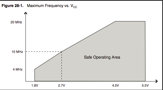
@bjacobse
reason behind 1mhz mcu is to run it on lower voltage but switching between speed still need higher voltage. if i m not wrong!!! -
@bjacobse
reason behind 1mhz mcu is to run it on lower voltage but switching between speed still need higher voltage. if i m not wrong!!!
Hello! It looks like you're interested in this conversation, but you don't have an account yet.
Getting fed up of having to scroll through the same posts each visit? When you register for an account, you'll always come back to exactly where you were before, and choose to be notified of new replies (either via email, or push notification). You'll also be able to save bookmarks and upvote posts to show your appreciation to other community members.
With your input, this post could be even better 💗
Register Login