Skip to content
  • MySensors
  • OpenHardware.io
  • Categories
  • Recent
  • Tags
  • Popular
Skins
  • Light
  • Brite
  • Cerulean
  • Cosmo
  • Flatly
  • Journal
  • Litera
  • Lumen
  • Lux
  • Materia
  • Minty
  • Morph
  • Pulse
  • Sandstone
  • Simplex
  • Sketchy
  • Spacelab
  • United
  • Yeti
  • Zephyr
  • Dark
  • Cyborg
  • Darkly
  • Quartz
  • Slate
  • Solar
  • Superhero
  • Vapor

  • Default (No Skin)
  • No Skin
Collapse
Brand Logo
  1. Home
  2. Hardware
  3. Gateway device

Gateway device

Scheduled Pinned Locked Moved Hardware
151 Posts 19 Posters 115.3k Views 21 Watching
  • Oldest to Newest
  • Newest to Oldest
  • Most Votes
Reply
  • Reply as topic
Log in to reply
This topic has been deleted. Only users with topic management privileges can see it.
  • tbowmoT Offline
    tbowmoT Offline
    tbowmo
    Admin
    wrote on last edited by
    #75

    updated the first post in the thread, with links to github project, and pdf of schematics (on github). So it will always point at the latest available one, so I don't have to remember that there is a forum thread to keep updated :)

    AnticimexA 1 Reply Last reply
    0
    • AnticimexA Offline
      AnticimexA Offline
      Anticimex
      Contest Winner
      wrote on last edited by
      #76

      Nice nice. I am very interested in this as I have more or less decided to swap to RF69 from RF24. Both for range and because I like the concept of having the radio handle the encryption on my signed packets (yep, I am paranoid as hell). Unfortunately, it means my current gateway has to go but I have made a "sensor evaluation board" (got the PCBs, still waiting for components). Once I get the components and can verify all the features I put on it I will publish it in this forum for those interested. It will still rely on Arduino modules and such so it is not the hard-core approach like the Sensebender Micro though.

      Do you feel secure today? No? Start requiring some signatures and feel better tomorrow ;)

      1 Reply Last reply
      0
      • tbowmoT tbowmo

        updated the first post in the thread, with links to github project, and pdf of schematics (on github). So it will always point at the latest available one, so I don't have to remember that there is a forum thread to keep updated :)

        AnticimexA Offline
        AnticimexA Offline
        Anticimex
        Contest Winner
        wrote on last edited by
        #77

        @tbowmo
        I believe you previously had the interrupt for RF69 connected. But it does not seem to be anymore. Any particular reason for skipping that?

        Do you feel secure today? No? Start requiring some signatures and feel better tomorrow ;)

        1 Reply Last reply
        0
        • tbowmoT Offline
          tbowmoT Offline
          tbowmo
          Admin
          wrote on last edited by
          #78

          @Anticimex

          I'm still rearranging things in the schematics, in order to get the best board layout :).

          Could we go with one combined irq for both radio modules? (rfm69/Nrf24)?

          / Thomas

          1 Reply Last reply
          0
          • AnticimexA Offline
            AnticimexA Offline
            Anticimex
            Contest Winner
            wrote on last edited by
            #79

            I see no reason why that would not work. I sure hope so as I did that on my board :)
            Both radios will never be connected (or at least in use) simultaneously so it should be ok.

            Do you feel secure today? No? Start requiring some signatures and feel better tomorrow ;)

            1 Reply Last reply
            0
            • tbowmoT Offline
              tbowmoT Offline
              tbowmo
              Admin
              wrote on last edited by
              #80

              @Anticimex

              could be someone got brainfreeze and decided to go with both radios at once in one setup.. On the other hand, we're not using IRQ for the nrf24 at the moment..

              AnticimexA 1 Reply Last reply
              0
              • tbowmoT tbowmo

                @Anticimex

                could be someone got brainfreeze and decided to go with both radios at once in one setup.. On the other hand, we're not using IRQ for the nrf24 at the moment..

                AnticimexA Offline
                AnticimexA Offline
                Anticimex
                Contest Winner
                wrote on last edited by
                #81

                @tbowmo
                Even so, the electrical properties of the interrupt outputs on the module should ensure no meltdown occurs. And I think the user would get bigger problems than just having to figure out the origin of the interrupt :)

                Do you feel secure today? No? Start requiring some signatures and feel better tomorrow ;)

                1 Reply Last reply
                0
                • AnticimexA Offline
                  AnticimexA Offline
                  Anticimex
                  Contest Winner
                  wrote on last edited by
                  #82

                  On the other hand, is there a usecase to provide HW interrupt functionality for a dagughterboard on the gateway? Since it will "by definition" have a solid power supply, any sensors using interrupts should be fine with the soft-interrupt options (have not looked into those myself though) or simply use polling. Power saving makes little sense in this case. The radios are probably better off with "real" interrupts (if we ever use them).

                  Do you feel secure today? No? Start requiring some signatures and feel better tomorrow ;)

                  1 Reply Last reply
                  0
                  • tbowmoT Offline
                    tbowmoT Offline
                    tbowmo
                    Admin
                    wrote on last edited by
                    #83

                    been fiddling with layout, and schematics changes..

                    Added a couple of MAX3002E for level conversion between 5V and 3V3 domains on the board. (Links to the schematic are in the first post of this thread)

                    MysensorsGW.png

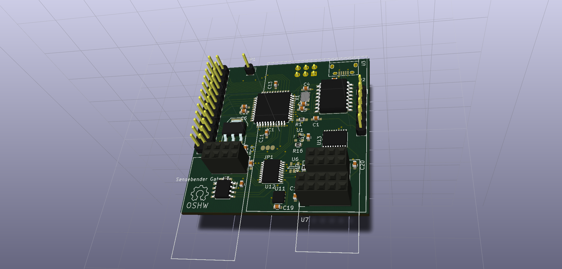
                    Waiting for samples of the ESP8266, and W5100 modules, so I can make some last measurements before ordering boards.

                    1 Reply Last reply
                    1
                    • pliniosenioreP Offline
                      pliniosenioreP Offline
                      plinioseniore
                      wrote on last edited by
                      #84

                      Hi,

                      just want to share with you some of our progress in a board similar to the one that you are designing.

                      This is based on Atmega32U4 and has socket for nRF24L01 and ESP8266 and is designed to be battery operated and support Grove connector. The board has mosfet to switch off the sensor while sleeping and keep low the consumption, this should stand a year on battery.

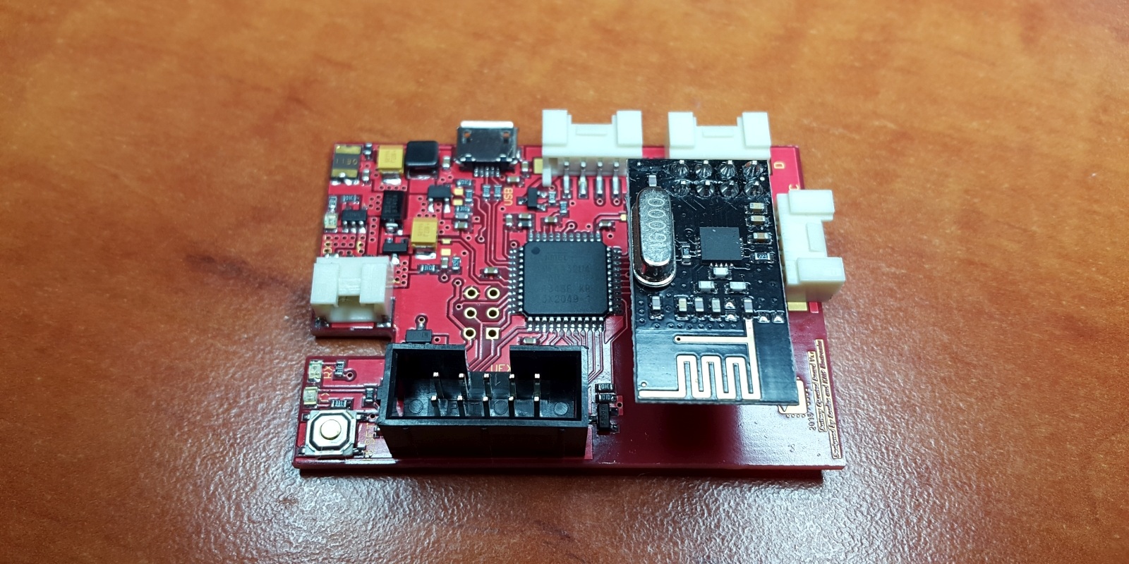
                      We just received the PCB, picture at the link below,
                      http://www.souliss.net/2015/06/sensor-battery-board-pcb-arrived.html

                      The schematic and layout are open-source and hope that this board may fit some needs also in the MySensor community
                      https://github.com/souliss/boards/tree/master/Battery_Operated_Board/Ver1

                      Regards,
                      Dario.

                      Souliss, Arduino and Android based SmartHome and IoT
                      http://www.souliss.net
                      @soulissteam

                      1 Reply Last reply
                      0
                      • tbowmoT Offline
                        tbowmoT Offline
                        tbowmo
                        Admin
                        wrote on last edited by
                        #85

                        @plinioseniore

                        Looks like a nice board you have created... Only problem is, that we run out of memory on atmega328, if we want to run with signing and have MQTT client on board.

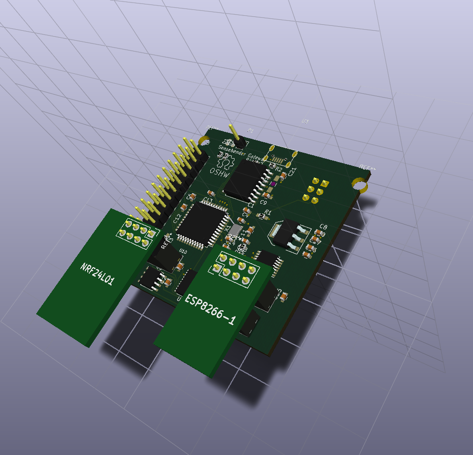
                        So that is why we have bumped the processor to a atmega1284 instead, having 4 times the memory, than atmega328. Also, with this board, we have the posibility to use both RFM69 and NRF24L01 on the sensor network..

                        1 Reply Last reply
                        0
                        • tbowmoT Offline
                          tbowmoT Offline
                          tbowmo
                          Admin
                          wrote on last edited by
                          #86

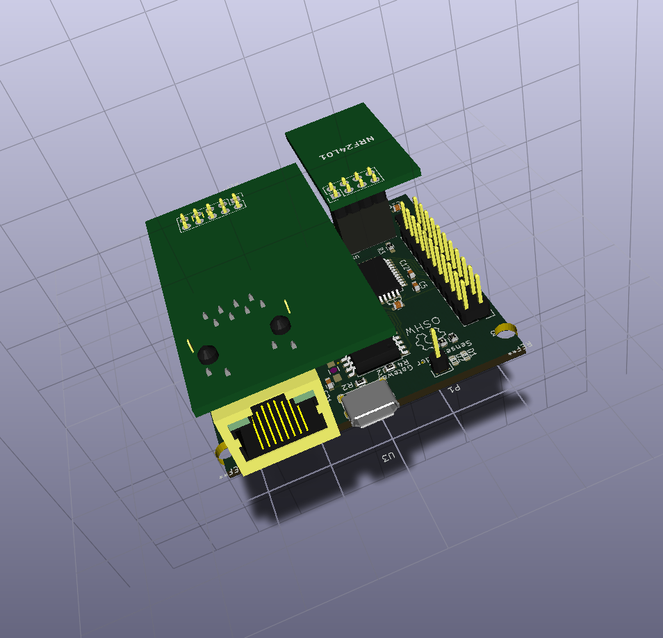
                          Tried to make a concept drawing, of NRF module placement

                          MysensorsGW-2.png

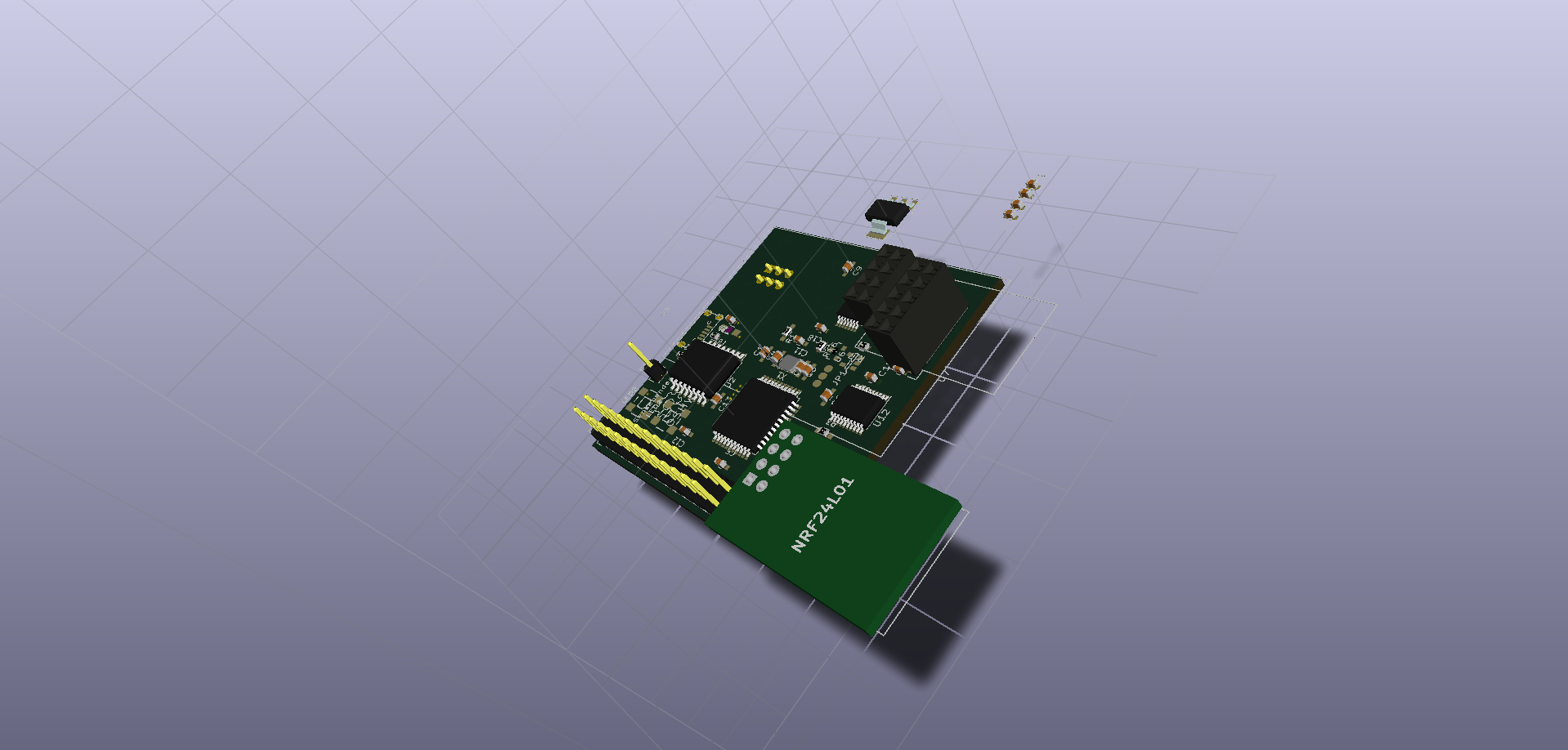
                          the esp8266 is placed in a similar way, on the right edge of the board, also hanging over the edge with the antenna part.

                          the W5100 board (which is similar to this one from itead studio) is turned 180 degrees, which makes the ethernet jack placement above the large "empty" space on the board (there is a 2x3 pinheader in the concept drawing)

                          The micro usb connector will be just beside the ethernet jack. between the ether jack, and the single pinheader pin (this is the antenna connection point for the rfm69 you can put on the bottom of the board)

                          Things are still a bit conceptual, trying to visualize it for my self :)

                          1 Reply Last reply
                          1
                          • R Offline
                            R Offline
                            rickmontana83
                            wrote on last edited by
                            #87

                            I'll second (third? fourth? whatever...) the suggestion to design this to fit a cheap and readily available enclosure. Something like:

                            http://www.aliexpress.com/item/Free-Shipping-Plastic-Waterproof-Clear-Cover-Electronic-Project-Box-Enclosure-Case-85-58-33MM/2025247551.html

                            (Not saying that's ideal; just an example.)

                            1 Reply Last reply
                            0
                            • tbowmoT Offline
                              tbowmoT Offline
                              tbowmo
                              Admin
                              wrote on last edited by
                              #88

                              @rickmontana83

                              the board is 50x50 mm, and with the radio / wifi protruding over the edge, this box should fit nicely.

                              The reason why I chose 50x50mm for the board size, is that it's either 50x50mm, or 100x100mm board when we order prototypes, which is more expensive. (And I like to make things small :))

                              1 Reply Last reply
                              0
                              • R Offline
                                R Offline
                                rickmontana83
                                wrote on last edited by
                                #89

                                Agree about smaller. Everything looks classier with less wasted space.

                                Probably too late now, but if the board had mounting holes that lined up with the enclosure that would be sweet. I'm always at a loss for how to keep my boards stable inside their plastic homes. Would love to hear peoples' solutions for mounting when the holes don't line up.

                                1 Reply Last reply
                                0
                                • tbowmoT Offline
                                  tbowmoT Offline
                                  tbowmo
                                  Admin
                                  wrote on last edited by
                                  #90

                                  @rickmontana83

                                  nothing's too late (yet). I haven't even ordered the first prototype batch yet. Still ironing out some details, and routing the PCB (I have only scratched the routing for the 10th time or so :s ). Actually I had thought about adding a couple of mounting holes in the board..

                                  I'll see if the boxes that I have, resembles the one that I just linked to.. (I've talked with @hek about finding some enclosures a couple of days ago, when we suddenly found a seller on ali express, that only had enclosures of various kinds).

                                  RJ_MakeR 1 Reply Last reply
                                  0
                                  • pliniosenioreP Offline
                                    pliniosenioreP Offline
                                    plinioseniore
                                    wrote on last edited by
                                    #91

                                    @tbowmo

                                    Yes the Atmega32U4 and Atmega328 has in the RAM their main problem, in our case we run smoothly in the 2KBytes available because we don't use ASCII in the protocol, but binary only.

                                    Then the board is for as a remote sensor node, running on battery, not a main gateway board.

                                    In any case, the board that you are designing will work nicely also with Souliss.battery_board-1.jpg

                                    Souliss, Arduino and Android based SmartHome and IoT
                                    http://www.souliss.net
                                    @soulissteam

                                    1 Reply Last reply
                                    0
                                    • tbowmoT tbowmo

                                      @rickmontana83

                                      nothing's too late (yet). I haven't even ordered the first prototype batch yet. Still ironing out some details, and routing the PCB (I have only scratched the routing for the 10th time or so :s ). Actually I had thought about adding a couple of mounting holes in the board..

                                      I'll see if the boxes that I have, resembles the one that I just linked to.. (I've talked with @hek about finding some enclosures a couple of days ago, when we suddenly found a seller on ali express, that only had enclosures of various kinds).

                                      RJ_MakeR Offline
                                      RJ_MakeR Offline
                                      RJ_Make
                                      Hero Member
                                      wrote on last edited by
                                      #92

                                      @tbowmo Mounting holes would be very good. :flushed:

                                      RJ_Make

                                      1 Reply Last reply
                                      0
                                      • tbowmoT Offline
                                        tbowmoT Offline
                                        tbowmo
                                        Admin
                                        wrote on last edited by
                                        #93

                                        ok now with mounting holes. Or sort of.. the holes are 4.8cm apart, center to center, and the pcb is 5cm wide. I have used this case as a template.

                                        MysensorsGW.png

                                        1 Reply Last reply
                                        1
                                        • tbowmoT Offline
                                          tbowmoT Offline
                                          tbowmo
                                          Admin
                                          wrote on last edited by
                                          #94

                                          and now with a w5100 module attached

                                          MysensorsGW-w5100.png

                                          1 Reply Last reply
                                          1
                                          Reply
                                          • Reply as topic
                                          Log in to reply
                                          • Oldest to Newest
                                          • Newest to Oldest
                                          • Most Votes


                                          12

                                          Online

                                          11.7k

                                          Users

                                          11.2k

                                          Topics

                                          113.1k

                                          Posts


                                          Copyright 2025 TBD   |   Forum Guidelines   |   Privacy Policy   |   Terms of Service
                                          • Login

                                          • Don't have an account? Register

                                          • Login or register to search.
                                          • First post
                                            Last post
                                          0
                                          • MySensors
                                          • OpenHardware.io
                                          • Categories
                                          • Recent
                                          • Tags
                                          • Popular