Anyone using/tried the E28-2G4M27S 2.4Ghz LoRa SX1280 27dB module?
-
@NeverDie said in Anyone using/tried the E28-2G4M27S 2.4Ghz LoRa SX1280 27dB module?:
@Larson said in Anyone using/tried the E28-2G4M27S 2.4Ghz LoRa SX1280 27dB module?:
@NeverDie said in Anyone using/tried the E28-2G4M27S 2.4Ghz LoRa SX1280 27dB module?:
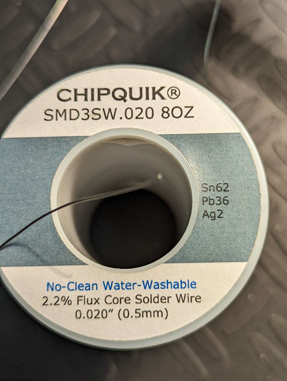
0.4mm diameter Kester Rosin solder.
I'll put it on my list. After the Male/Female antennae discussion above, I'm sure I got my order wrong - so I'll have a new running list shortly when everything arrives. I checked my solder with a caliper since the dimensions are listed in Chinese: it is 0.6 mm so I'm not far away. I do like the feel the smaller diameter has in comparison to my larger solder so I'm sure 0.4 mm will even be better.
Yeah, I was using 0.635mm MG Chemicals solder previously, but I found I had to drown the radio modules in rosin flux afterward to eliminate solder bridges, etc. Perhaps part of the difference may be that Kester uses a different formulation for its in-line flux than MG Chemicals? I suppose that could also have something to do with it. So, maybe it's not entirely diameter, but having now worked with the two different diameters, my gut intuition is that the smaller diameter is helping.
Anyone else reading this having any opinions on the matter that they are willing to share?
I swear by the stuff in the picture below. It melts at a lower temperature(179 C) so, as an amateur, I feel safer keeping my iron at a lower temp and in place a little longer when I am working with IC's. I like that it's thin too as it is easier to control how much you apply. I have no issues with it, it flows well and doesn't create bridges (unless I use too much).
@alphaHotel & @NeverDie: My ChipQuik kit arrived as did the SRA flux. Look forward to working with it. I find the "No-Clean" claim concerning but I am armed with my new 99% alcohol just in case.
@NeverDie: The PPK2 is great. I did a few tests and captures today - no logic-port evaluation yet. It will take me another day to learn the fuse settings. Yes, Gammon is the master of the fuse subject as I learned with PIC chips. More on PPK2: I’m using the LowPower library (Felix R. I think). After sleep, the PPK tells me that the current is 4 uA. Zeesh, with the 18650 LiOn battery decay rate of 28’ish uA, I’m not sure if I need fuse settings. Well, there is the optimization of the thing, so I will press on. -
@alphaHotel & @NeverDie: My ChipQuik kit arrived as did the SRA flux. Look forward to working with it. I find the "No-Clean" claim concerning but I am armed with my new 99% alcohol just in case.
@NeverDie: The PPK2 is great. I did a few tests and captures today - no logic-port evaluation yet. It will take me another day to learn the fuse settings. Yes, Gammon is the master of the fuse subject as I learned with PIC chips. More on PPK2: I’m using the LowPower library (Felix R. I think). After sleep, the PPK tells me that the current is 4 uA. Zeesh, with the 18650 LiOn battery decay rate of 28’ish uA, I’m not sure if I need fuse settings. Well, there is the optimization of the thing, so I will press on.@Larson Yeah, I think of "No Clean" as really being "easier to clean." There's still some residue with those that I have tried, but they really are easier to clean up after than the regular flux.
So I still prefer them, but I don't like to leave them uncleaned. Maybe the residue isn't corrosive like regular flux? At any rate I don't trust it either.
-
@Larson Here's all you need to know in one place on how to get to 100na sleep current on the atmega328p: https://www.gammon.com.au/power He covers all the different methods. TL;DR: burn your fuses to:
External: 0xFF
High: 0xDC
Low: 0xC2
and then run Sketch J from the Nick Gammon link. That's all there is to it, provided you have an external device/circuit to wake up your atmega328p.@NeverDie said in Anyone using/tried the E28-2G4M27S 2.4Ghz LoRa SX1280 27dB module?:
@Larson Here's all you need to know in one place on how to get to 100na sleep current on the atmega328p: https://www.gammon.com.au/power He covers all the different methods. TL;DR: burn your fuses to:
External: 0xFF
High: 0xDC
Low: 0xC2
and then run Sketch J from the Nick Gammon link. That's all there is to it, provided you have an external device/circuit to wake up your atmega328p.It sounded so simple. Today I gave it a shot. The fuse setting is just like I remembered it: complicated. The bottom line is that, using Sketch J, I am able to get down to 0.25 uA even without changing fuses. Not that I didn’t try to change fuses. I got out my USBASP and have been bootloading and fuse-setting all day. I used avrdude and had trouble getting the commands to work right (conf file directory must be specified.) I tried your recommended fuse settings but then couldn’t upload programs. So, I changed back to default fuse settings and still couldn’t upload programs. Seems to be that another bootloader reset got me back to normal. So… if I can get to 0.25 uA, I’m super happy. The additional 0.1 uA reduction is just too difficult for me. I'm not exactly sure how this helps in the radio stuff, but it has been a really good excercise of my new PPK2 device. I am very impressed.
I’m kind of shocked that the PPK2 has that granularity. As Gammon indicated with Sketch J, I could ground D2 (INT0) to cause an interrupt to blink the LED. That on its own is a valuable tool. Here is a picture. Thanks for holding my hand in this stuff – it has been most helpful.
-
@Larson Something I only just recently started using in the last couple of days that you may like: 0.4mm diameter Kester Rosin solder. It's ridiculously thin, but for soldering radio modules onto boards, I'm finding that I can more precisely put just enough solder exactly where I want it without having to apply solder flux to the module afterward.
@NeverDie said in Anyone using/tried the E28-2G4M27S 2.4Ghz LoRa SX1280 27dB module?:
Something I only just recently started using in the last couple of days that you may like: 0.4mm diameter Kester Rosin solder. It's ridiculously thin, but for soldering radio modules onto boards, I'm finding that I can more precisely put just enough solder exactly where I want it without having to apply solder flux to the module afterward.
I'm out shoping for this solder. I can find this 20 mil solder, but not the 0.4 mm (16 mil) stuff. Do you have a link?
-
@NeverDie said in Anyone using/tried the E28-2G4M27S 2.4Ghz LoRa SX1280 27dB module?:
@Larson said in Anyone using/tried the E28-2G4M27S 2.4Ghz LoRa SX1280 27dB module?:
@NeverDie said in Anyone using/tried the E28-2G4M27S 2.4Ghz LoRa SX1280 27dB module?:
0.4mm diameter Kester Rosin solder.
I'll put it on my list. After the Male/Female antennae discussion above, I'm sure I got my order wrong - so I'll have a new running list shortly when everything arrives. I checked my solder with a caliper since the dimensions are listed in Chinese: it is 0.6 mm so I'm not far away. I do like the feel the smaller diameter has in comparison to my larger solder so I'm sure 0.4 mm will even be better.
Yeah, I was using 0.635mm MG Chemicals solder previously, but I found I had to drown the radio modules in rosin flux afterward to eliminate solder bridges, etc. Perhaps part of the difference may be that Kester uses a different formulation for its in-line flux than MG Chemicals? I suppose that could also have something to do with it. So, maybe it's not entirely diameter, but having now worked with the two different diameters, my gut intuition is that the smaller diameter is helping.
Anyone else reading this having any opinions on the matter that they are willing to share?
I swear by the stuff in the picture below. It melts at a lower temperature(179 C) so, as an amateur, I feel safer keeping my iron at a lower temp and in place a little longer when I am working with IC's. I like that it's thin too as it is easier to control how much you apply. I have no issues with it, it flows well and doesn't create bridges (unless I use too much).
@alphaHotel said in Anyone using/tried the E28-2G4M27S 2.4Ghz LoRa SX1280 27dB module?:
I swear by the stuff in the picture below. It melts at a lower temperature(179 C) so, as an amateur, I feel safer keeping my iron at a lower temp and in place a little longer when I am working with IC's. I like that it's thin too as it is easier to control how much you apply. I have no issues with it, it flows well and doesn't create bridges (unless I use too much).
On your recommendation I'm looking for this solder as well. For those who follow this thread I found it here.
The solder diameter that came with my Chipquick SMD1 Removal kit was enough for one job, maybe. The linked 4 Oz. supply will last some time for me.
-
@NeverDie said in Anyone using/tried the E28-2G4M27S 2.4Ghz LoRa SX1280 27dB module?:
Something I only just recently started using in the last couple of days that you may like: 0.4mm diameter Kester Rosin solder. It's ridiculously thin, but for soldering radio modules onto boards, I'm finding that I can more precisely put just enough solder exactly where I want it without having to apply solder flux to the module afterward.
I'm out shoping for this solder. I can find this 20 mil solder, but not the 0.4 mm (16 mil) stuff. Do you have a link?
@Larson said in Anyone using/tried the E28-2G4M27S 2.4Ghz LoRa SX1280 27dB module?:
I'm out shoping for this solder. I can find this 20 mil solder, but not the 0.4 mm (16 mil) stuff. Do you have a link?
It is Kester 24-6337-0007 https://www.amazon.com/KESTER-SOLDER-24-6337-0007-WIRE-183°C/dp/B00DDDHF2W/ref=sr_1_2?keywords=Kester+24-6337-0007&qid=1655879942&sr=8-2 That's half the price that mouser would charge for the exact same thing. Go figure.
-
@alphaHotel said in Anyone using/tried the E28-2G4M27S 2.4Ghz LoRa SX1280 27dB module?:
I swear by the stuff in the picture below. It melts at a lower temperature(179 C) so, as an amateur, I feel safer keeping my iron at a lower temp and in place a little longer when I am working with IC's. I like that it's thin too as it is easier to control how much you apply. I have no issues with it, it flows well and doesn't create bridges (unless I use too much).
On your recommendation I'm looking for this solder as well. For those who follow this thread I found it here.
The solder diameter that came with my Chipquick SMD1 Removal kit was enough for one job, maybe. The linked 4 Oz. supply will last some time for me.
@Larson said in Anyone using/tried the E28-2G4M27S 2.4Ghz LoRa SX1280 27dB module?:
On your recommendation I'm looking for this solder as well. For those who follow this thread I found it here.
The solder diameter that came with my Chipquick SMD1 Removal kit was enough for one job, maybe. The linked 4 Oz. supply will last some time for me.That's not quite the same stuff. What I use has a small amount of silver content in the alloy. You can find it here at Mouser.com. The smallest size they have though is the 8oz which is basically, a lifetime supply for me at least.
-
@Larson said in Anyone using/tried the E28-2G4M27S 2.4Ghz LoRa SX1280 27dB module?:
I'm out shoping for this solder. I can find this 20 mil solder, but not the 0.4 mm (16 mil) stuff. Do you have a link?
It is Kester 24-6337-0007 https://www.amazon.com/KESTER-SOLDER-24-6337-0007-WIRE-183°C/dp/B00DDDHF2W/ref=sr_1_2?keywords=Kester+24-6337-0007&qid=1655879942&sr=8-2 That's half the price that mouser would charge for the exact same thing. Go figure.
@NeverDie and
@alphaHotelThanks for the links. I'm going for the silver (Ag)! The little that I remember from physics is that silver has high conductivity and low melting point. Perfect. Too bad it is so expensive.
I have a few dental crowns that could be remelted and ...
-
@Larson said in Anyone using/tried the E28-2G4M27S 2.4Ghz LoRa SX1280 27dB module?:
@NeverDie said in Anyone using/tried the E28-2G4M27S 2.4Ghz LoRa SX1280 27dB module?:
In its favor is that at 40na the sleep current...
I'll order several. Then compare to the TrigBoards. Adafruit's TPL5011 advertises a run current of 20uA. Is that acceptable for you? If so I'll buy several. Couple of limitations for me: 1. Time - I'm about a month out, 2. My Ammeter is a standard DMM from Harbor Freight. The smallest range is 200uA and I've found it very useful. Certainly fine enough to show the 20uA, but inadequate for nanoAmps.
Hmmmm... Something's wrong then with Adafruit's design if it's 20uA. The chip itself consumes only 35na according to its datasheet:
https://www.ti.com/lit/ds/symlink/tpl5110.pdf?ts=1652658923819&ref_url=https%253A%252F%252Fwww.google.com%252F
Maybe their p-channel mosfet has high leakage current with the circuit has they've designed it? I would pass if it really is 20uA. I'm sure I could do better than that.You need something like either a Current Ranger or a MicroCurrent Gold to accurately measure microamps and nanoamps. Cost is around $100.
Also, I just now looked at one of Kevin Darrah's videos:
https://www.youtube.com/watch?v=WNH6tyQpwF4where he has embraced ESP-NOW. He said his esp8266 still takes around 1.5 seconds to wake up and transmit, even though running ESP-NOW, which is a very long time, as the module will be burning current through out that wake-up interval. In the example he showed, the delay was quite noticeable (though definitely an improvement compared to before when he was using plain wi-fi). Of course, the devil is in the details, but seeing that I'm more skeptical now than before.
From the MySensors forum entry:
@NeverDie said in Anyone using/tried the E28-2G4M27S 2.4Ghz LoRa SX1280 27dB module?:
Hmmmm... Something's wrong then with Adafruit's design if it's 20uA. The chip itself consumes only 35na according to its datasheet:
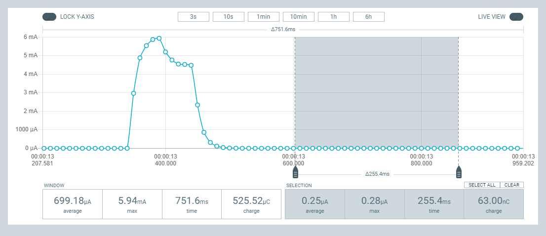
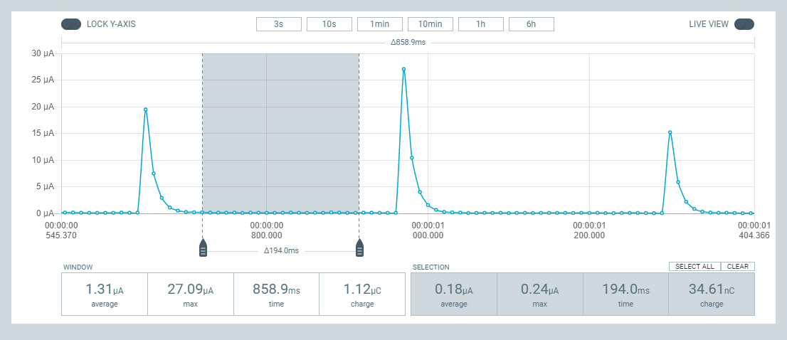
https://www.ti.com/lit/ds/symlink/tpl5110.pdf?ts=1652658923819&ref_url=https%3A%2F%2Fwww.google.com%2FMy TPL5110's arrived and I hooked one up to the PPKII to take a look. Remember that Adafruit advertised a disappointing OFF-state current of 20 uA. Fortunately, I have found this not to be the case. Instead, my PPKII shows the off state to be 120 nA; picture attached. The load I used was an LED hooked up to a resistor and the PPK is supplied with 3.3V. As earlier discussed, I’ll next dig out the TrigBoards that Kevin Darrah sent me to see how they do.
-
From the MySensors forum entry:
@NeverDie said in Anyone using/tried the E28-2G4M27S 2.4Ghz LoRa SX1280 27dB module?:
Hmmmm... Something's wrong then with Adafruit's design if it's 20uA. The chip itself consumes only 35na according to its datasheet:
https://www.ti.com/lit/ds/symlink/tpl5110.pdf?ts=1652658923819&ref_url=https%3A%2F%2Fwww.google.com%2FMy TPL5110's arrived and I hooked one up to the PPKII to take a look. Remember that Adafruit advertised a disappointing OFF-state current of 20 uA. Fortunately, I have found this not to be the case. Instead, my PPKII shows the off state to be 120 nA; picture attached. The load I used was an LED hooked up to a resistor and the PPK is supplied with 3.3V. As earlier discussed, I’ll next dig out the TrigBoards that Kevin Darrah sent me to see how they do.
@Larson Thanks for posting your measurements. Mine match up with yours: https://forum.mysensors.org/topic/11954/most-reliable-best-radio/20?_=1656174349755
I just yesterday put together a TPL5111 to serve as purely a wake-up timer for a sleeping MCU, and it's working well also in that capacity.
-
@Larson Thanks for posting your measurements. Mine match up with yours: https://forum.mysensors.org/topic/11954/most-reliable-best-radio/20?_=1656174349755
I just yesterday put together a TPL5111 to serve as purely a wake-up timer for a sleeping MCU, and it's working well also in that capacity.
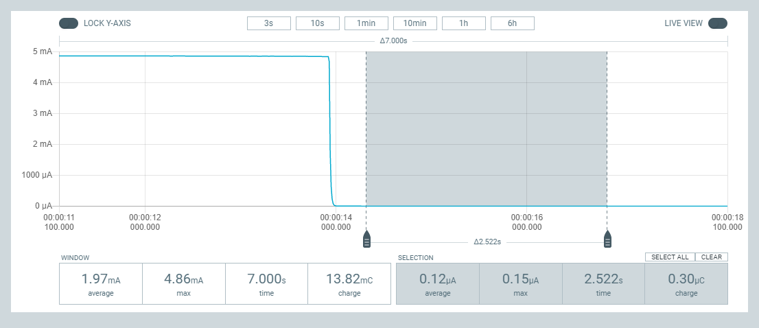
@NeverDie Here is my report on the Kevin Darrah Trigboard (V8.1) as promised. Fundamentally, the power draw of this board is about as low as the TPL5110. His board ships with door monitoring firmware on it that is conducting some kind of polling every 320 mS, it appears. Between the polling the current draw is about 180 nA, per my PPKII. If one were to include the polling activity, then the average current is about 1.3 uA. A picture of this is below. If an alarm condition is achieved, the device makes an internet connection and broadcasts a message to third-party servers that will alert the user by phone/text/email. Of course, that takes time (between 2 to 3 seconds), and additional current.
If you have 30 minutes, Kevin has a start-up video that is very informative. He makes the point that this board consumes a small fraction of what smoke detectors use. While the PPKII shows that the Trigboard has an equivalent sleep current, the Trigboard delivers the monitoring function for additional, though modest, current. As before, I find value in comparing these tiny currents to the expected shelf-life burn rate that is orders of magnitude (at least one) higher.
This was my first exposure to ESP32’s. Kevin indicates that the performance of the ESP32 is better than the ESP8266. I like the idea of Bluetooth access for being able to configure devices, as Kevin shows, and for access to sensor data – especially in development & debugging. I have not reviewed his firmware that he generously has made available. His “Configurator” firmware looks to be a great example of how to build user menus to input variables. This looks like the new form of the older WiFi Manager libraries which have been very useful.
-
@Larson I haven't studied Kevin's solution, so maybe I'm missing the point of it, but the adafruit TPL5110 BoB is so much less expensive and draws so little current that it seems like no contest to me.
@NeverDie You have a point. The TPL is also simpler.
But bless the developer. Yes, I was trying to hype his product. I forgot to mention that doing this current test was really easy because this thing just worked... right out of the box (really, out of the anti-static bag.) Rarely have things work so quickly for me. Even the TPL required fumbling.
So if sleeping is the objective and timing isn't really important, then the TPL it is. But if configuration settings, Bluetooth, ADC, I2C, SPI and timing are relevant, then the Trigboard is the way to go.
-
@NeverDie said in Anyone using/tried the E28-2G4M27S 2.4Ghz LoRa SX1280 27dB module?:
I'm hoping (but haven't confirmed) that by eliminating the oscillator on pins D20 and D21, I can use those pins to drive two LED's kinda "for free" since nobody uses those pins for anything.
Reporting back: I have the answer. It turns out that the standard arduino core for atmega328p that's baked into the standard Arduino IDE does not support Arduino pins 20 and 21 as digital GPIO pins for driving LEDs. However, the good news is that there's an even better Arduino core, called MCUDude MiniCore which does support exactly those pins for such purposes. Here's the TL;DR:
This core gives you two extra IO pins if you're using the internal oscillator! PB6 and PB7 is mapped to Arduino pin 20 and 21.
https://mcudude.github.io/MiniCore/package_MCUdude_MiniCore_index.json
It's very easy to use. You can install it into the regular Arduino IDE, pick from among the MiniCore "boards" in the board manager, select the 8Mhz option and a few other obvious options, and then you're done with instalation. From that point on your code will automagically compile using MiniCore. Just to be sure, I gave it a try myself, and I'm now blinking a blue LED off of Ardino Pin 20. It works!@NeverDie said in Anyone using/tried the E28-2G4M27S 2.4Ghz LoRa SX1280 27dB module?:
https://mcudude.github.io/MiniCore/package_MCUdude_MiniCore_index.json
It's very easy to use. You can install it into the regular Arduino IDE, pick from among the MiniCore "boards" in the board manager, select the 8Mhz option and a few other obvious options, and then you're done with instalation. From that point on your code will automagically compile using MiniCore. Just to be sure, I gave it a try myself, and I'm now blinking a blue LED off of Ardino Pin 20. It works!I leave this post as a reminder to anyone else reading this thread. The MCUDude link and installation step is VERY important. To install in the Arduino IDE add the link in File/Preferences/Additional Board Manager URLs; go to Board Manager and filter on minicore, click on Install when MiniCore comes up. Next when selecting the MiniCore board, make sure to select Clock as Internal (8 MHz), or avrdude won't be able to find your board. I went with the other board manager defaults and ... WaLa... my new barebones board is blinking on both pins 20 and 21. Overlooking, or not remembering, this May 14 post has cost me several weeks. So if you build yourself a barebones, heed this post.
-
@NeverDie said in Anyone using/tried the E28-2G4M27S 2.4Ghz LoRa SX1280 27dB module?:
https://mcudude.github.io/MiniCore/package_MCUdude_MiniCore_index.json
It's very easy to use. You can install it into the regular Arduino IDE, pick from among the MiniCore "boards" in the board manager, select the 8Mhz option and a few other obvious options, and then you're done with instalation. From that point on your code will automagically compile using MiniCore. Just to be sure, I gave it a try myself, and I'm now blinking a blue LED off of Ardino Pin 20. It works!I leave this post as a reminder to anyone else reading this thread. The MCUDude link and installation step is VERY important. To install in the Arduino IDE add the link in File/Preferences/Additional Board Manager URLs; go to Board Manager and filter on minicore, click on Install when MiniCore comes up. Next when selecting the MiniCore board, make sure to select Clock as Internal (8 MHz), or avrdude won't be able to find your board. I went with the other board manager defaults and ... WaLa... my new barebones board is blinking on both pins 20 and 21. Overlooking, or not remembering, this May 14 post has cost me several weeks. So if you build yourself a barebones, heed this post.
@Larson said in Anyone using/tried the E28-2G4M27S 2.4Ghz LoRa SX1280 27dB module?:
@NeverDie said in Anyone using/tried the E28-2G4M27S 2.4Ghz LoRa SX1280 27dB module?:
https://mcudude.github.io/MiniCore/package_MCUdude_MiniCore_index.json
It's very easy to use. You can install it into the regular Arduino IDE, pick from among the MiniCore "boards" in the board manager, select the 8Mhz option and a few other obvious options, and then you're done with instalation. From that point on your code will automagically compile using MiniCore. Just to be sure, I gave it a try myself, and I'm now blinking a blue LED off of Ardino Pin 20. It works!I leave this post as a reminder to anyone else reading this thread. The MCUDude link and installation step is VERY important. To install in the Arduino IDE add the link in File/Preferences/Additional Board Manager URLs; go to Board Manager and filter on minicore, click on Install when MiniCore comes up. Next when selecting the MiniCore board, make sure to select Clock as Internal (8 MHz), or avrdude won't be able to find your board. I went with the other board manager defaults and ... WaLa... my new barebones board is blinking on both pins 20 and 21. Overlooking, or not remembering, this May 14 post has cost me several weeks. So if you build yourself a barebones, heed this post.
Thanks for your post. I just now pasted it into the project's main description page on openhardware.io: https://www.openhardware.io/view/22651/Version-30-atmega328p-test-platform
-
@NeverDie said in Anyone using/tried the E28-2G4M27S 2.4Ghz LoRa SX1280 27dB module?:
https://mcudude.github.io/MiniCore/package_MCUdude_MiniCore_index.json
It's very easy to use. You can install it into the regular Arduino IDE, pick from among the MiniCore "boards" in the board manager, select the 8Mhz option and a few other obvious options, and then you're done with instalation. From that point on your code will automagically compile using MiniCore. Just to be sure, I gave it a try myself, and I'm now blinking a blue LED off of Ardino Pin 20. It works!I leave this post as a reminder to anyone else reading this thread. The MCUDude link and installation step is VERY important. To install in the Arduino IDE add the link in File/Preferences/Additional Board Manager URLs; go to Board Manager and filter on minicore, click on Install when MiniCore comes up. Next when selecting the MiniCore board, make sure to select Clock as Internal (8 MHz), or avrdude won't be able to find your board. I went with the other board manager defaults and ... WaLa... my new barebones board is blinking on both pins 20 and 21. Overlooking, or not remembering, this May 14 post has cost me several weeks. So if you build yourself a barebones, heed this post.
@Larson
I suppose the design could be changed to include an optional diode on pin 13 for those who want to stay strictly orthodox Arduino.One could also allow a crystal oscillator to be installed, for those who want that as well, but I happen to think running from a crystal oscillator is generally a bad idea for a battery powered application, especially when the 8Mhz resonator seems to work so well.
-
@Larson
I suppose the design could be changed to include an optional diode on pin 13 for those who want to stay strictly orthodox Arduino.One could also allow a crystal oscillator to be installed, for those who want that as well, but I happen to think running from a crystal oscillator is generally a bad idea for a battery powered application, especially when the 8Mhz resonator seems to work so well.
@NeverDie said in Anyone using/tried the E28-2G4M27S 2.4Ghz LoRa SX1280 27dB module?:
...but I happen to think running from a crystal oscillator is generally a bad idea for a battery powered application...
No, don't change the design. I think you have a platform with a specific low power intent - including the education of others (like me). Matter of fact, I've got several battery projects that would be FAR better by changing to the on-chip clock, and new core. And so far, we are only using the 8 MHz setting. In the MiniCore the choices go to 1 MHz.
Back when I was... on PIC's... I bought 32 KHz crystals to minimize power. I just didn't know enough to use them and I still don't. But I'm working that direction and you have helped A BUNCH including you're idea of friends sitting around the table exchanging bits and bytes in a MISO/MOSI/SCK kind of way. I'm gathering that if you have control of the clock, you could have it all.
Besides you, Kevin Darrah, and Felix @ LowPowerLabs have also made great contributions to the low-power idea. I just haven't dedicated enough energy, yet, to their efforts.
16 MHz is impractically fast when so many designs just need low power.
I wanna go back to school,
DogWithA_Bone -
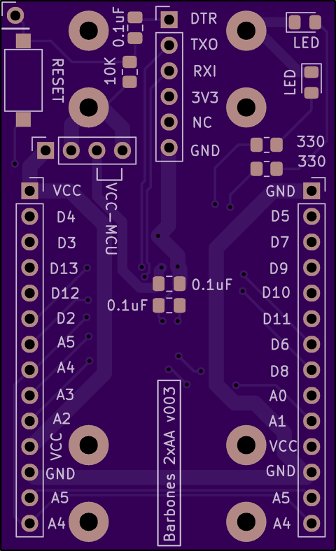
Here are the pin labels for the V001 barebones board for mounting on headers. The document I prepared for this wouldn't upload, but had nice lefthand/righthand orientations. This made it easier than having to open the CAD file everytime I needed to make connections.
But here is what I did in MS Word:
Turn on grid set spacing to 0.1"
Turn on ruler
Copy the below text
Align to the right or left as you wish
Font Calibri 5.5
Verify spacing (14 pins = 1.4")
PrintI also made columns and multiple copies of the below with both alignments. I have two boards built. Maybe you have more. Hope it helps.
GND
D5
D7
D9
D10/SS
D11/MOSI
D6
D8
A0
A1
VCC
GND
A5/SCL
A4/SDAVCC
D4
D3
D13/SCK
D12/MISO
D2/INTO
A5/SCL
A4/SDA
A3
A2
VCC
GND
A5/SCL
A4/SDADTR
RXTX
TXRX
VCC
X
GND[8/6/22 edit: reversed TX and RX as noted above - just incase someone has use for it]
-
@NeverDie Yea, I think I knew you upversioned the silkscreen. I think I remember you commenting on it. Looks pretty. BUT in my effort to add to the community, since I typed it for my self for my V001 boards, I thought I'd share it incase there is anybody like me with V001.
I like the V003 upgrades, specially that reset bypass via as discussed with @alphaHotel . Maybe I'll try it. I've got so much into my little V001's (yours actually) that I just can't give-em up. When I get the boards rigged up with radios, GPS (on the USART bus) and SD Card reader (on the SPI bus with a different CS), I'll shoot and send a picture in the spirit of a party!