Anyone using/tried the E28-2G4M27S 2.4Ghz LoRa SX1280 27dB module?
-
CDEbyte had a sale, and I snapped up a bunch of them at $1.20 each (free shipping included!). Now I need to figure out what to do with them. I'm assuming that a generic SX1280 arduino library will interface to it, but I haven't dug into it at all. I'd like to set it up with the SHT45 TH sensor, which, as near as I can tell, seems like it will be the best temp-humidity sensor on the market when it releases (supposedly sometime this quarter): https://sensirion.com/products/catalog/SHT45/
Highlights: 0.1C temperature acurracy, and 1% relative humidity accuracy, with a 0% to 100% range, and just a 0.4ua average current draw. I've acquired a bunch of precision tools that I'm going to keep in dry boxes to keep them from rusting, and my plan is to use this as a way to monitor and guarantee that the dry boxes are sufficiently dry, or else need a desiccant renewal. Although I was tempted to use commercial TH sensors, since they're so cheap these days, a LoRa/SHT45 sensor would likely be far more capable and hence worth the effort. -
This is an interesting find, can you share the link? I can't find these low prices anywhere.
@electrik Here:
https://www.aliexpress.com/item/1005003897673336.html?spm=a2g0o.order_list.0.0.21ef1802o2L1ibI like that it has a PCB antenna built into it. That way I don't need some wire antenna sticking out of it, flapping in the breeze so to speak.
Maybe they were just unloading their US inventory, for whatever reason. If it weren't for the crazy low price, I would have gone for the SX1260, which seems to be a newer, improved generation. That said, this guy was able to get a 40km range out of his 2.4ghz SX1280 module (some other brand of module) using just 4dB transmit power: https://github.com/StuartsProjects/SX1280_Testing
so the SX1280 chip itself is no slouch. He estimates " a potential range of 80km LOS at 10dBm", and so my module, having 27dB, would presumably beat that handily if it were to use full power--which I have no intention of doing. Rather, just the opposite: with such a large link budget, I should be able to run it at extremely low Tx power in a domestic environment, probably below the noise floor even (a neat trick that LoRa is allegedly capable of doing). On the other hand, for those who are interested in joining up with the LoRaWAN community, the high transmit distance might be a strong selling point, especially in these early days when the nearest friendly node might be quite a distance away from you. The advantage of that, of course, is that it's free, and it might give you IoT backup connectivity for those brief occasions when your regular ISP goes down. Not sure how they keep freeriders out of the system, but maybe it's like torrents, where you build up credit in the community by taking other people's traffic when you can, and they in-turn reciprocate when you need it. Ideally, they'd have a different ISP, or, if not, can at least pass your traffic to someone else on the LoRaWAN who has a different ISP than you. If you were also running Amazon Sidewalk, then you'd have yet additional redundancy (but, that's a different topic entirely). All that said, with all the hacking going on, I really do like the idea of running below the noise floor--seems like yet another layer of security. -
For anyone who may be interested, I found a basic breakout board for this module here: https://easyeda.com/jbk1/e28-adapter
It's nothing fancy, but I suppose you maybe get more ground plane than if you were to just solder on some castellated pins.
You can download the gerber and then etch or fab however you want. It's a nice luxury when someone else has already done the work! In my case 3 boards from oshpark is probably the cheapest option to test out a simple ping-pong pair of transceivers to verify whether the available library software for it works (as I presume it will), with no extra cost to upgrade to 2oz copper. $7.10.Not sure what the SHT45 will be priced at. It's supposed to "release" sometime this quarter (i.e. before the end of March), but who knows how long it will take from then until it becomes available at mouser/digikey/arrow or wherever. I suppose I could live with the SHT41, which is about $4 per chip on mouser, quantity 1, and already in stock. I haven't yet checked, but with luck the SHT45 would be pin compatible for future builds down the road. If it really does on average draw only 0.4ua current, then maybe it could wakeup your MCU whenever there's a temp/RH change, which would maybe be nicer than waking up your MCU with a timer interrupt to poll the sensor to see if anything has changed.
-
@NeverDie said in Anyone using/tried the E28-2G4M27S 2.4Ghz LoRa SX1280 27dB module?:
ey'd have a different ISP, or, if not, can at least pass your traffic to someone else on the LoRaWAN who has a different ISP than you. If you were also running Amazon Sidewalk, then you'
@NeverDie. Thanks for your write-up. Before I lose my train of thought and go look at StuartsProjects I have to ask about the EasyEDA design: doesn't it make TX/RX much better with no groundplane around the antenna? I've just completed a 433 MHz project and found that I was better to get the TX side way off my groundplaned board. Also, I've noticed that other ESP8266 breakouts dutifully remove the groundplane from breakout boards that would be near the ESP's built-in PCB antenna.
I don't know much about radio's so can easily accept any comment for the better, or even ridicule. I've learned as much as I can about radios from Andreas Spiess. He would simply test the difference with a RF sensor.
@Larson Good catch! Yes, indeed, that breakout board will be no good for a trace antenna. Dang! I ordered it from oshpark on the assumption the designer knew what he was doing, but thanks to you I can now see that it's absolutely FUBAR. Because of that I'll have to use an external antenna with it. :angry: I suppose in theory I could scrape off that part of the ground plane which lay below the trace antenna.... Better yet, I'll completely saw off the top portion of the breakout board so that there's nothing below the trace antenna at all:
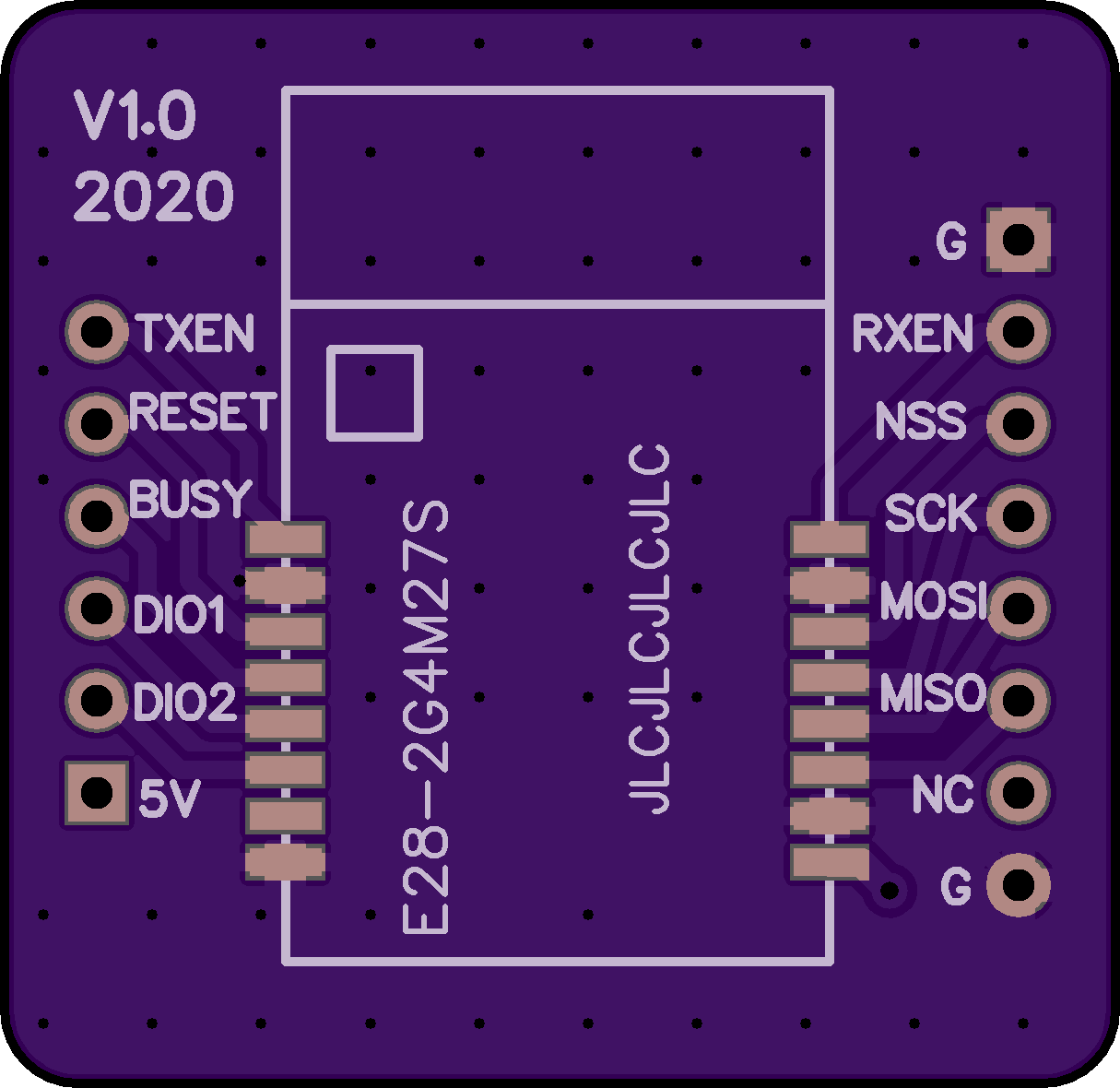
Thanks for pointing out that fatal flaw! I suppose it might be OK with an external antenna, but definitely not for a trace antenna without some post processing to fix it.
-
Something I'm less sure about is that the author placed ground planes on both sides of the PCB:
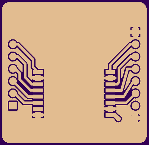
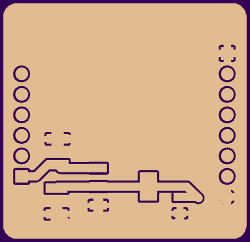
Even though the two ground planes are connected together with enough vias to make a colander, I do wonder whether this arrangement might introduce at least some amount of unanticipated capacitance. Anyone know? Is this best practice, or would it have been better to keep the ground plane on one side only?
-
@Larson Good catch! Yes, indeed, that breakout board will be no good for a trace antenna. Dang! I ordered it from oshpark on the assumption the designer knew what he was doing, but thanks to you I can now see that it's absolutely FUBAR. Because of that I'll have to use an external antenna with it. :angry: I suppose in theory I could scrape off that part of the ground plane which lay below the trace antenna.... Better yet, I'll completely saw off the top portion of the breakout board so that there's nothing below the trace antenna at all:
Thanks for pointing out that fatal flaw! I suppose it might be OK with an external antenna, but definitely not for a trace antenna without some post processing to fix it.
@NeverDie. Thanks for the comment. I'm not sure if I've got that ground-plane radio interferance thing right. Maybe there is a SMD socket thing in which a radio could be clipped so you don't have to commit a radio to the board to find out. I've not seen one but I've not looked. Maybe it is time to invent one with springs to receive castellated edges. A jig like that would also serve ESP8266's. I like the PTH sockets for this kind of experimentation.
The idea of sawing off the top just north of the TXEN/RXEN connections is good. Maybe you could do that after mounting so you could test before AND after. That would be definitive.
On the other hand a redesign and reorder from OSHPark can't be that much of a setback. I really enjoy their service. They happen to be less than 5 miles from my home - but they ship globally. Small world.
Let me know what you learn. I'll learn with you much as I have been doing with hundreds of your other posts - and I thank you. -
I recently purchased a Yolink gateway and some Yolong LoRa devices to go with it. For whatever reason, the radio link isn't rock solid--and, yes, I'm running the most curent firmware--whereas my DIY LoRa devices that I made years ago are totally rock solid. Hence, I still have reason to make my own LoRa circuits and firmware, even though I'd frankly prefer to just buy something off-the-shelf. It's these kind of shortfalls that led me into designing my own circuits in the first place. Perhaps it will be forever thus. :face_with_rolling_eyes:
-
Reporting back: it turns out that accurately sawing off the upper part of the PCB was one of those "easier said than done" type of things, so I'm starting over and creating my own E28-2G4M27S breakout board in KiCAD from scratch. I wasn't a fan of KiCAD previously, but I'm finding KiCAD 6, which is the current release, is much improved! I'll post my breakout board here at mysensors after I've had it fabbed and validated that it is correct.
The datasheet for E28-2G4M27S doesn't have dimensions which show exactly where the antenna traces start and end, so I'll measure that with a micrometer and use my own measurement for that to generate the silkscreen delimiter for that region and to ensure that the copper ground plane doesn't run beneath the trace antenna. I'll be deliberately over conservative so as to better ensure there's no overlap.
-
Looking at the module itself:
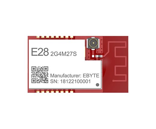
I suppose one could maybe argue that the antenna chain starts just prior to where the IPX antenna connector sits, so I'll remove groundplane from anywhere to the left of it just to be sure. Looking at the above photo, that may(?) be overkill, as it looks as though for the IPX connector to be active the resistor would need to be removed and a solderbridge installed in order to make the IPX connector active. As I'm not entirely sure though, I'll simply assume a worst case scenario and then build to that. -
Something I'm less sure about is that the author placed ground planes on both sides of the PCB:
Even though the two ground planes are connected together with enough vias to make a colander, I do wonder whether this arrangement might introduce at least some amount of unanticipated capacitance. Anyone know? Is this best practice, or would it have been better to keep the ground plane on one side only?
Good to know! I found this video which I think may answer to my earlier question above:
https://www.youtube.com/watch?v=ySuUZEjARPY
Basically, for high frequency communications, the return path in the ground plane is directly beneath the trace. For this reason, rule #1 is to never route across splits in the ground plane:

Therefore, for a two sided board, the ideal would be to have a prestine ground plane on the bottom layer. Adding another "ground plane" on the top layer is effectively an oxymoron. According to the presenter, routing across a split in the ground plane, as in the cut channel of case #2, can cause considerable EMI problems.
-
Here's the breakout board for it that I just now made using KiCAD version 6: https://www.openhardware.io/view/8304/E28-2G4M27S-24GHz-LoRa-Breakout-Board
IMHO, this breakout board should be much better than the breakout board done by the other guy that I referenced earlier in this thread. -
Here's the breakout board for it that I just now made using KiCAD version 6: https://www.openhardware.io/view/8304/E28-2G4M27S-24GHz-LoRa-Breakout-Board
IMHO, this breakout board should be much better than the breakout board done by the other guy that I referenced earlier in this thread.@NeverDie - I gotta say the Rick Hartley video has been really helpful to understand ground planes. At about 14:00 he nails it: "the energy is in the field". When learning electric-magnetic force, I didn't think that the energy is in the field (i.e. magnetic). I only have 2 hours to go to learn more! Thank you.
-
Here's the breakout board for it that I just now made using KiCAD version 6: https://www.openhardware.io/view/8304/E28-2G4M27S-24GHz-LoRa-Breakout-Board
IMHO, this breakout board should be much better than the breakout board done by the other guy that I referenced earlier in this thread.@NeverDie Sorry to bother again... but I gotta say this Hartley traning video has been monumental. I always thought the world was divided into AC and DC. NOW, I think I get it: DC circuits flipping on and off at a SIGNAL frequency are actually AC just with a different voltage basis. The KEY, Hartley says, is that the energy is not in the trace, but in the field during the rise and fall of voltage. This is also helping me to finally understand inductance. WHY didn't they say this 40 years ago in school? Oh, perhaps I was sleeping as I did.
This is a breakthrough that may lead me to understanding antennae theory and a bunch of other stuff. I thank you for the introduction. I gotta go find this Hartley fellow to thank him. -
@NeverDie Sorry to bother again... but I gotta say this Hartley traning video has been monumental. I always thought the world was divided into AC and DC. NOW, I think I get it: DC circuits flipping on and off at a SIGNAL frequency are actually AC just with a different voltage basis. The KEY, Hartley says, is that the energy is not in the trace, but in the field during the rise and fall of voltage. This is also helping me to finally understand inductance. WHY didn't they say this 40 years ago in school? Oh, perhaps I was sleeping as I did.
This is a breakthrough that may lead me to understanding antennae theory and a bunch of other stuff. I thank you for the introduction. I gotta go find this Hartley fellow to thank him.@Larson Glad you liked it. If you're interested in the theory of it, then you may find this a worthwhile survey of some of the big ideas:
https://www.youtube.com/watch?v=bHIhgxav9LYPlainly it's a deep topic, so I'm relieved whenever I find simple design rules of thumb which make it possible to do successful projects without having to peel back everything to first principles. ;-)
-
@Larson Glad you liked it. If you're interested in the theory of it, then you may find this a worthwhile survey of some of the big ideas:
https://www.youtube.com/watch?v=bHIhgxav9LYPlainly it's a deep topic, so I'm relieved whenever I find simple design rules of thumb which make it possible to do successful projects without having to peel back everything to first principles. ;-)
@NeverDie Yes, I strive to not reinvent also. But it is nice to know why wheels are round. So I dug a little further on this ground plane subject and I’m conflicted. At 40:42 on this video, ground planes are discussed. In short, he discourages the use of ground planes. So I ask myself, what design is used on an ESP8266 itself. Certainly, they use the best design standards to minimize EMI since they manufacture these radios by the millions. To find out I get out my zacto knife and scrape off some of the masking of the ESP and check for ground. Sure enough they use ground planes everywhere except for under the antennae. Go figure.
[Edit 5/30/22. After listening to the link in my post again, I’m realizing that I was wrong to say Eric Bogatin discourages ground planes. I think I’ve learned that he discourages the use of copper fills on signal layers. Big difference. It was unclear in the referenced video segment that the three experimental boards with different trace distributions had a ground plane below, but I believe that was the case.]
-
@NeverDie Yes, I strive to not reinvent also. But it is nice to know why wheels are round. So I dug a little further on this ground plane subject and I’m conflicted. At 40:42 on this video, ground planes are discussed. In short, he discourages the use of ground planes. So I ask myself, what design is used on an ESP8266 itself. Certainly, they use the best design standards to minimize EMI since they manufacture these radios by the millions. To find out I get out my zacto knife and scrape off some of the masking of the ESP and check for ground. Sure enough they use ground planes everywhere except for under the antennae. Go figure.
[Edit 5/30/22. After listening to the link in my post again, I’m realizing that I was wrong to say Eric Bogatin discourages ground planes. I think I’ve learned that he discourages the use of copper fills on signal layers. Big difference. It was unclear in the referenced video segment that the three experimental boards with different trace distributions had a ground plane below, but I believe that was the case.]
@Larson AFAIK, the biggest reason to have a ground plane in a radio system is to improve the performance of a whip antenna. I'm not sure what's ideal, but, for example, https://www.digi.com/support/knowledge-base/does-a-1-4-wave-antenna-need-a-ground-plane recommends a 3 inch radius groundplane for a 2.4Ghz radio if the antenna were put in the very middle of it. Well,that would be a 6 inch diameter ground plane! Not a great option for tiny IOT devices.
Fortunately, it does concede that "The antenna can still work on a smaller ground plane but the efficiency will be reduced." On the other hand, if you're using a dipole antenna, then maybe (?) the ground plane isn't so important. Not entirely sure.Anyhow, if you find out anything more, I'd be interested.
-
I'm an engineer, though not RF. My understanding, from short discussions years ago with RF engineers, was that the ground planes have strong effects on antenna performance.
Depending on the design of the antenna, sometimes you want the ground plane and sometimes you don't.
But that's the extent of what I remember. (And it could be that I've even got errors in that little bit.) But basically to go with whatever the antenna designer recommended, because there are reasons for it. Just because one design calls for it and the other doesn't, it doesn't make either of them wrong.
Without the deep understanding myself, and not having however much testing equipment necessary to check the results, I try to stick as close to what the manufacturer/designer calls for as possible.
Hello! It looks like you're interested in this conversation, but you don't have an account yet.
Getting fed up of having to scroll through the same posts each visit? When you register for an account, you'll always come back to exactly where you were before, and choose to be notified of new replies (either via email, or push notification). You'll also be able to save bookmarks and upvote posts to show your appreciation to other community members.
With your input, this post could be even better 💗
Register Login