Most reliable "best" radio
-
This is what I came up with for a platform that has both pluggable MCU's and pluggable radios:
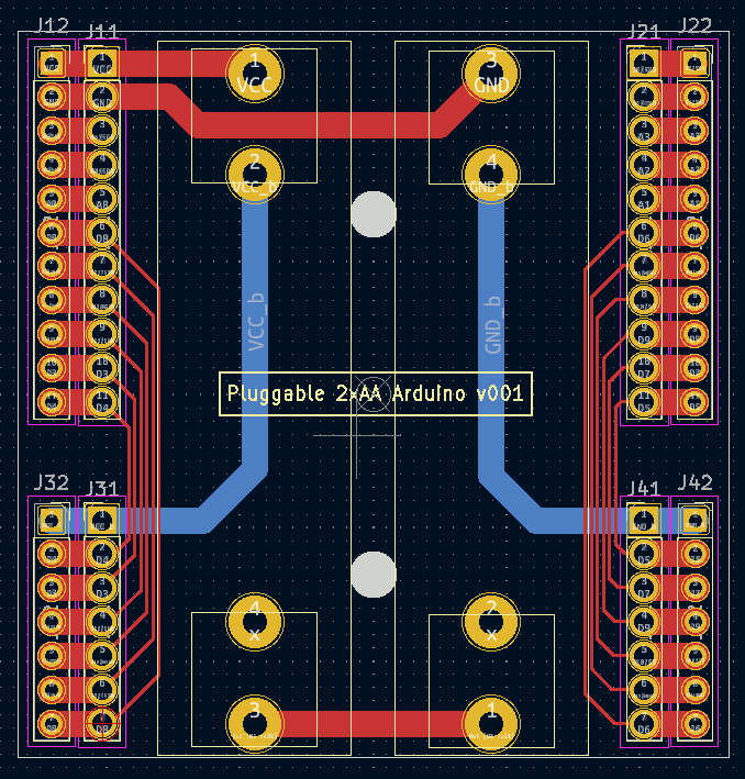
It's a bit wider than the previous test platform to give enough space between both the two AA batteries themselves and between those batteries and the pin headers. It also has a separate row of pins along the outside in case you want to have any shields that go on top. I did away with the switch entirely. Now if you want to power it off, you just remove a battery. So, doing all that renders the backplane/power-source very simple. Also, I included two mounting holes so that the whole thing can be mounted inside a project box. Yesterday I ordered this PCB along with a pluggable atmega328p MCU board and a pluggable radio board from a fab, so nothing physical to show-and-tell just yet.
-
@alphaHotel said in Most reliable "best" radio:
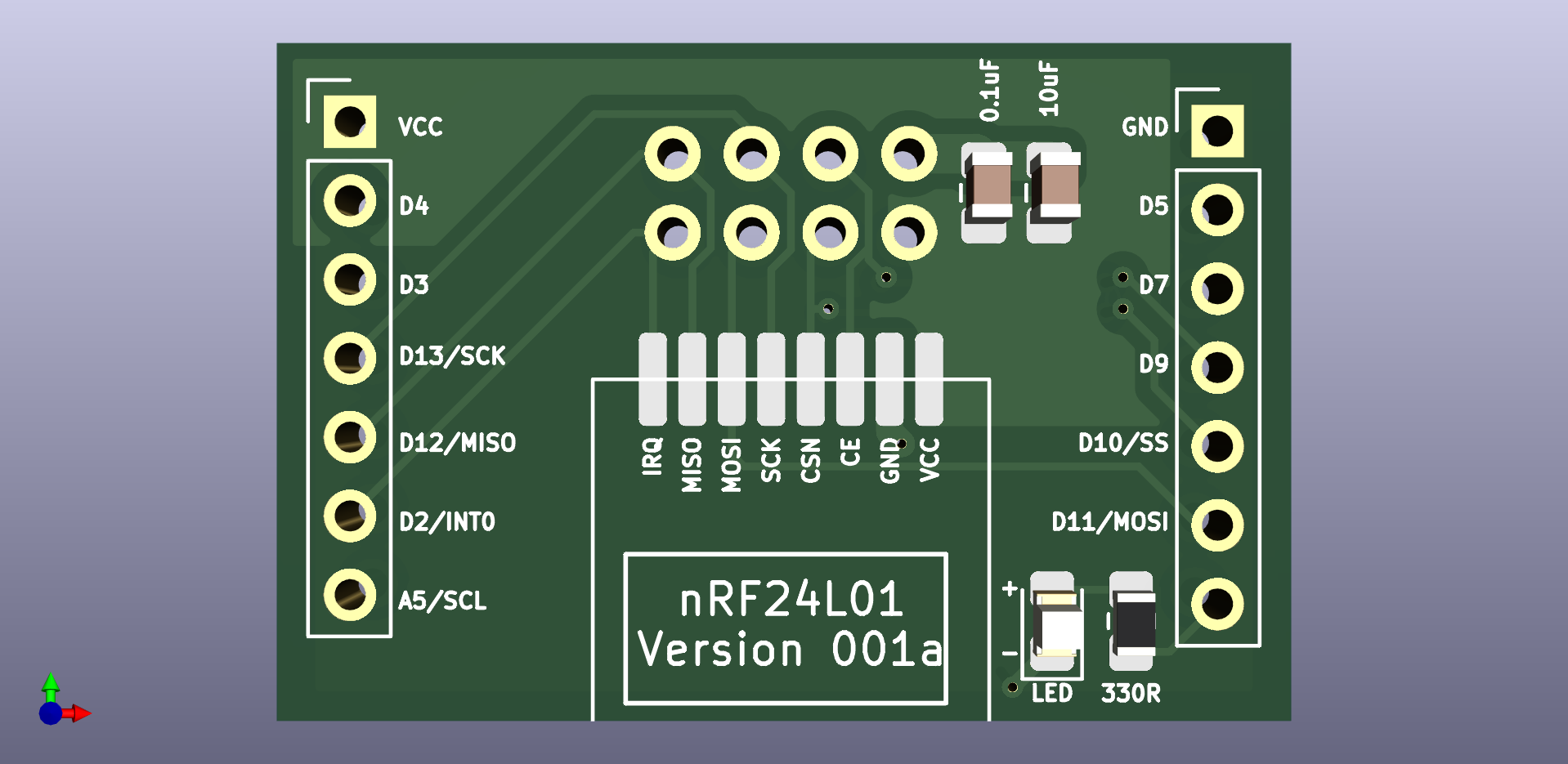
On a related note, would it be possible to get the Kicad files for the nRF24L01 adapter board?
Done. Posted the .rar file to the project files. Let me know if you have any difficulty with it.
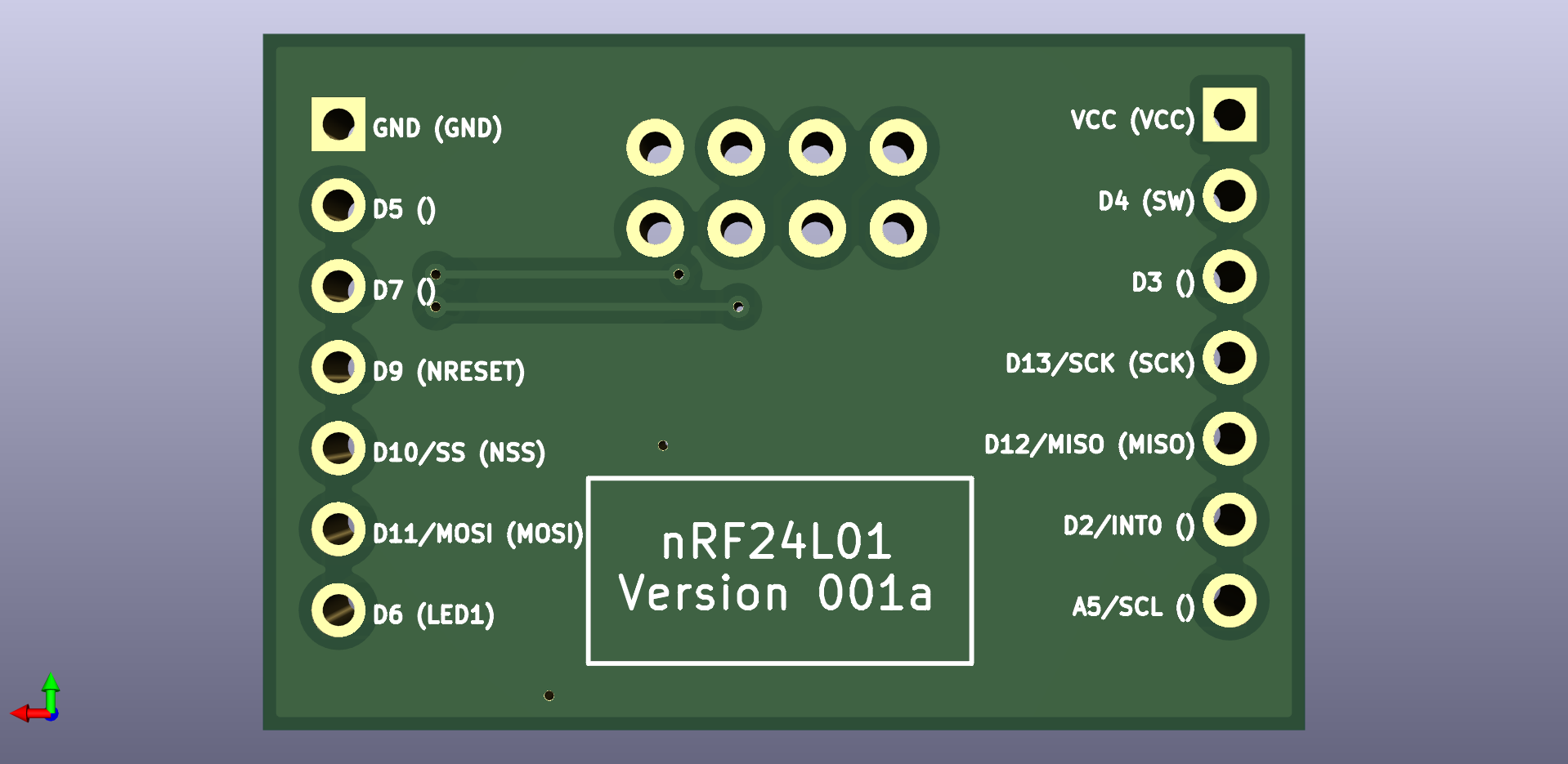
There was an error in the original: it didn't identify the IRQ pin on the backside silkscreen. I fixed that on the next (experimental) version (which is also wider), which I haven't yet received from the fab. However, the silkscreen images are here:
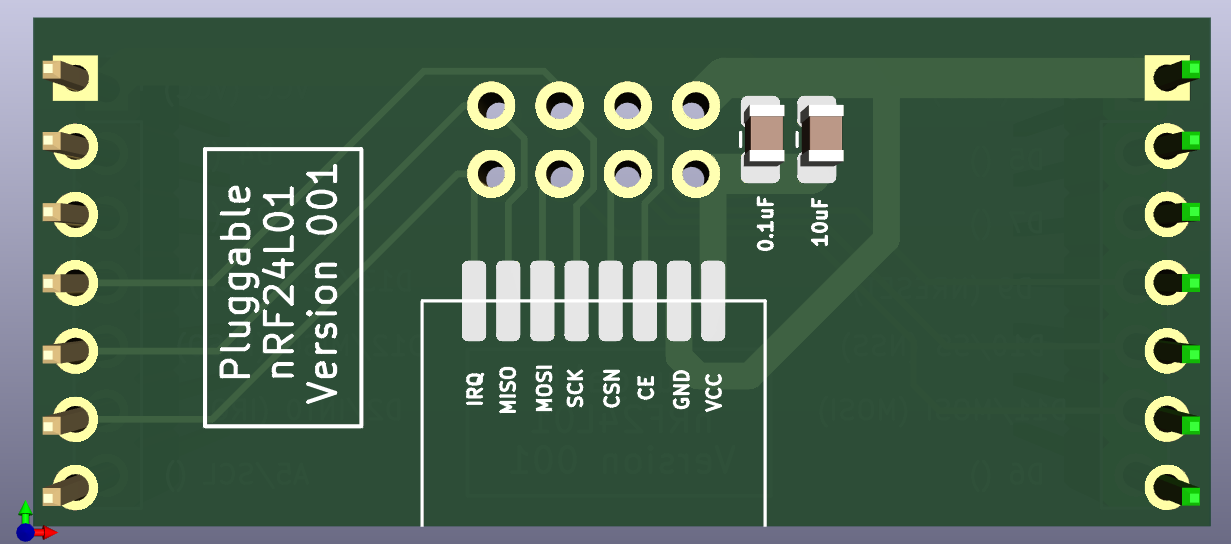
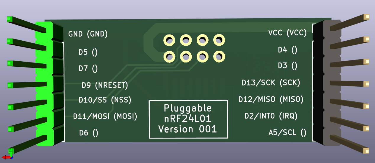
Hope that helps!
P.S. In case you're wondering, the possible next version has not only pluggable radios (as the original version had), but also pluggable MCU's, to make it easier to try different MCU's. I'm not sure yet whether or not it's a good idea, but since it's not rocket surgery I figure it is just easier to try the idea out than to overthink it.
@NeverDie said in Most reliable "best" radio:
Done. Posted the .rar file to the project files. Let me know if you have any difficulty with it.
Thank you. I didn't have any issues with the files though it did warn that the footprints for the radio modules are in
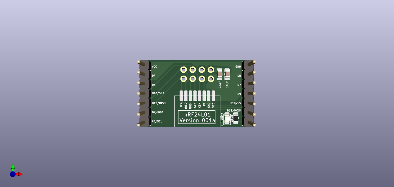
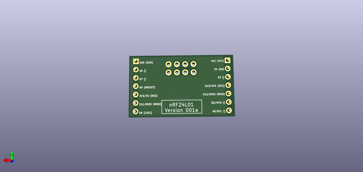
MyGlobalLibrary, which I don't have. See the screenshot below. If they could be put into a library within the project, it would be more portable than it already is but I was able to work with it as is.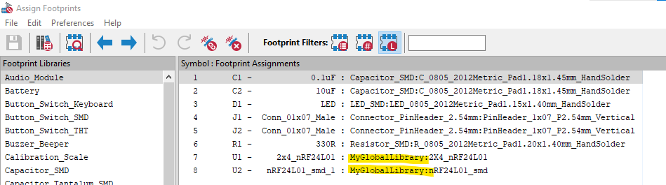
I made a few mods including adding a ground plane and I'll try to get a repo on GitHub up and running for it tonight after work. With a new version in the works, perhaps I'll hold off getting some of these boards fabricated. In the interim, here's a view of my 3D model.
P.S. In case you're wondering, the possible next version has not only pluggable radios (as the original version had), but also pluggable MCU's, to make it easier to try different MCU's. I'm not sure yet whether or not it's a good idea, but since it's not rocket surgery I figure it is just easier to try the idea out than to overthink it.
At one point in this thread, I marvelled at the battery shield and wondered about having it separated from the MCU. Just conditioned power on the first shield then MCU, then radio. The complexity of it though is beyond my current level as I don't have as much experience with alternative MCU's (though I've been thinking we need to start looking at something with more program memory, like the ATmega4808/9). On the other hand, it should be just a matter of defining what needs to be passed from shield to shield (layer to layer?). Power, ground, SPI signals, perhaps I2C signals and a few other GPIO signals. Please do though consider lining up the pins such that they would also fit a breadboard layout.
-
This is what I came up with for a platform that has both pluggable MCU's and pluggable radios:
It's a bit wider than the previous test platform to give enough space between both the two AA batteries themselves and between those batteries and the pin headers. It also has a separate row of pins along the outside in case you want to have any shields that go on top. I did away with the switch entirely. Now if you want to power it off, you just remove a battery. So, doing all that renders the backplane/power-source very simple. Also, I included two mounting holes so that the whole thing can be mounted inside a project box. Yesterday I ordered this PCB along with a pluggable atmega328p MCU board and a pluggable radio board from a fab, so nothing physical to show-and-tell just yet.
-
@NeverDie With the first version of the battery/MCU board, you lamented running traces directly under the batteries. You have the space now to re-route them but choose not to. Did you find a way to resolve the issue it caused?
@alphaHotel said in Most reliable "best" radio:
@NeverDie With the first version of the battery/MCU board, you lamented running traces directly under the batteries. You have the space now to re-route them but choose not to. Did you find a way to resolve the issue it caused?
Actually, I fixed it on the new version (pictured above). The red traces run on top, so they're adequately isolated from the battery holder metal, which is on the back side except for the through-holes where it sticks through the board. Where I ran into trouble was running traces on the back side, beneath the battery holder metal. If the battery holder metal was pressed up hard against the board, some shorts resulted on some of the boards. The workaround was to not press the battery holder metal hard up against the board, but the new version removes that concern entirely.
-
@NeverDie said in Most reliable "best" radio:
Done. Posted the .rar file to the project files. Let me know if you have any difficulty with it.
Thank you. I didn't have any issues with the files though it did warn that the footprints for the radio modules are in
MyGlobalLibrary, which I don't have. See the screenshot below. If they could be put into a library within the project, it would be more portable than it already is but I was able to work with it as is.I made a few mods including adding a ground plane and I'll try to get a repo on GitHub up and running for it tonight after work. With a new version in the works, perhaps I'll hold off getting some of these boards fabricated. In the interim, here's a view of my 3D model.
P.S. In case you're wondering, the possible next version has not only pluggable radios (as the original version had), but also pluggable MCU's, to make it easier to try different MCU's. I'm not sure yet whether or not it's a good idea, but since it's not rocket surgery I figure it is just easier to try the idea out than to overthink it.
At one point in this thread, I marvelled at the battery shield and wondered about having it separated from the MCU. Just conditioned power on the first shield then MCU, then radio. The complexity of it though is beyond my current level as I don't have as much experience with alternative MCU's (though I've been thinking we need to start looking at something with more program memory, like the ATmega4808/9). On the other hand, it should be just a matter of defining what needs to be passed from shield to shield (layer to layer?). Power, ground, SPI signals, perhaps I2C signals and a few other GPIO signals. Please do though consider lining up the pins such that they would also fit a breadboard layout.
@alphaHotel said in Most reliable "best" radio:
On the other hand, it should be just a matter of defining what needs to be passed from shield to shield (layer to layer?). Power, ground, SPI signals, perhaps I2C signals and a few other GPIO signals.
Yup, you got it. That's all there is to it. Power, ground, SPI, chip enable, chip select, maybe RX/TX enable (on some radios), and enough interrupt pins to take advantage of whatever interrupt or DIO pins the radio has to offer up. Looking back on it, I probably should have kept A5 off of the radio module, since that's used by I2C, and used some other pin instead. So... it's still a work in progress, but getting better.
-
@NeverDie said in Most reliable "best" radio:
Done. Posted the .rar file to the project files. Let me know if you have any difficulty with it.
Thank you. I didn't have any issues with the files though it did warn that the footprints for the radio modules are in
MyGlobalLibrary, which I don't have. See the screenshot below. If they could be put into a library within the project, it would be more portable than it already is but I was able to work with it as is.I made a few mods including adding a ground plane and I'll try to get a repo on GitHub up and running for it tonight after work. With a new version in the works, perhaps I'll hold off getting some of these boards fabricated. In the interim, here's a view of my 3D model.
P.S. In case you're wondering, the possible next version has not only pluggable radios (as the original version had), but also pluggable MCU's, to make it easier to try different MCU's. I'm not sure yet whether or not it's a good idea, but since it's not rocket surgery I figure it is just easier to try the idea out than to overthink it.
At one point in this thread, I marvelled at the battery shield and wondered about having it separated from the MCU. Just conditioned power on the first shield then MCU, then radio. The complexity of it though is beyond my current level as I don't have as much experience with alternative MCU's (though I've been thinking we need to start looking at something with more program memory, like the ATmega4808/9). On the other hand, it should be just a matter of defining what needs to be passed from shield to shield (layer to layer?). Power, ground, SPI signals, perhaps I2C signals and a few other GPIO signals. Please do though consider lining up the pins such that they would also fit a breadboard layout.
@alphaHotel said in Most reliable "best" radio:
I didn't have any issues with the files though it did warn that the footprints for the radio modules are in MyGlobalLibrary, which I don't have. See the screenshot below. If they could be put into a library within the project, it would be more portable than it already is but I was able to work with it as is.
Thanks for the feedback. I really would like it to be both portable and standalone, so I'll look into setting up a standalone library to include into the .rar that will make for a better KiCAD 6 project archive.
-
@alphaHotel said in Most reliable "best" radio:
@NeverDie With the first version of the battery/MCU board, you lamented running traces directly under the batteries. You have the space now to re-route them but choose not to. Did you find a way to resolve the issue it caused?
Actually, I fixed it on the new version (pictured above). The red traces run on top, so they're adequately isolated from the battery holder metal, which is on the back side except for the through-holes where it sticks through the board. Where I ran into trouble was running traces on the back side, beneath the battery holder metal. If the battery holder metal was pressed up hard against the board, some shorts resulted on some of the boards. The workaround was to not press the battery holder metal hard up against the board, but the new version removes that concern entirely.
@NeverDie said in Most reliable "best" radio:
@alphaHotel said in Most reliable "best" radio:
@NeverDie With the first version of the battery/MCU board, you lamented running traces directly under the batteries. You have the space now to re-route them but choose not to. Did you find a way to resolve the issue it caused?
Actually, I fixed it on the new version (pictured above). The red traces run on top, so they're adequately isolated from the battery holder metal, which is on the back side except for the through-holes where it sticks through the board. Where I ran into trouble was running traces on the back side, beneath the battery holder metal. If the battery holder metal was pressed up hard against the board, some shorts resulted on some of the boards. The workaround was to not press the battery holder metal hard up against the board, but the new version removes that concern entirely.
Okay, I see now. I misunderstood the original issue and also didn't think about the top/bottom side orientation in relation to those traces vis-a-vis the battery holders. Thanks for clarifying.
-
@NeverDie said in Most reliable "best" radio:
Done. Posted the .rar file to the project files. Let me know if you have any difficulty with it.
Thank you. I didn't have any issues with the files though it did warn that the footprints for the radio modules are in
MyGlobalLibrary, which I don't have. See the screenshot below. If they could be put into a library within the project, it would be more portable than it already is but I was able to work with it as is.I made a few mods including adding a ground plane and I'll try to get a repo on GitHub up and running for it tonight after work. With a new version in the works, perhaps I'll hold off getting some of these boards fabricated. In the interim, here's a view of my 3D model.
P.S. In case you're wondering, the possible next version has not only pluggable radios (as the original version had), but also pluggable MCU's, to make it easier to try different MCU's. I'm not sure yet whether or not it's a good idea, but since it's not rocket surgery I figure it is just easier to try the idea out than to overthink it.
At one point in this thread, I marvelled at the battery shield and wondered about having it separated from the MCU. Just conditioned power on the first shield then MCU, then radio. The complexity of it though is beyond my current level as I don't have as much experience with alternative MCU's (though I've been thinking we need to start looking at something with more program memory, like the ATmega4808/9). On the other hand, it should be just a matter of defining what needs to be passed from shield to shield (layer to layer?). Power, ground, SPI signals, perhaps I2C signals and a few other GPIO signals. Please do though consider lining up the pins such that they would also fit a breadboard layout.
@alphaHotel said in Most reliable "best" radio:
I didn't have any issues with the files though it did warn that the footprints for the radio modules are in MyGlobalLibrary, which I don't have. See the screenshot below. If they could be put into a library within the project, it would be more portable than it already is but I was able to work with it as is.
OK, I updated the project archive to include nRF24L01 symbol and footprint libraries which include those symbols and footprints. Let me know if it works out OK.
Apparently best practice is to put literally every single symbol and footprint that gets used on a project into project-specific libraries so that they can be freely shared. At least for now I just put in the unique nRF24L01 symbols and footprints that aren't part of the generic KiCAD 6 build.
-
@NeverDie said in Most reliable "best" radio:
Done. Posted the .rar file to the project files. Let me know if you have any difficulty with it.
Thank you. I didn't have any issues with the files though it did warn that the footprints for the radio modules are in
MyGlobalLibrary, which I don't have. See the screenshot below. If they could be put into a library within the project, it would be more portable than it already is but I was able to work with it as is.I made a few mods including adding a ground plane and I'll try to get a repo on GitHub up and running for it tonight after work. With a new version in the works, perhaps I'll hold off getting some of these boards fabricated. In the interim, here's a view of my 3D model.
P.S. In case you're wondering, the possible next version has not only pluggable radios (as the original version had), but also pluggable MCU's, to make it easier to try different MCU's. I'm not sure yet whether or not it's a good idea, but since it's not rocket surgery I figure it is just easier to try the idea out than to overthink it.
At one point in this thread, I marvelled at the battery shield and wondered about having it separated from the MCU. Just conditioned power on the first shield then MCU, then radio. The complexity of it though is beyond my current level as I don't have as much experience with alternative MCU's (though I've been thinking we need to start looking at something with more program memory, like the ATmega4808/9). On the other hand, it should be just a matter of defining what needs to be passed from shield to shield (layer to layer?). Power, ground, SPI signals, perhaps I2C signals and a few other GPIO signals. Please do though consider lining up the pins such that they would also fit a breadboard layout.
@alphaHotel said in Most reliable "best" radio:
Please do though consider lining up the pins such that they would also fit a breadboard layout.
Yes, agreed. Unless I made an error, this should already be true.
-
@alphaHotel said in Most reliable "best" radio:
I didn't have any issues with the files though it did warn that the footprints for the radio modules are in MyGlobalLibrary, which I don't have. See the screenshot below. If they could be put into a library within the project, it would be more portable than it already is but I was able to work with it as is.
OK, I updated the project archive to include nRF24L01 symbol and footprint libraries which include those symbols and footprints. Let me know if it works out OK.
Apparently best practice is to put literally every single symbol and footprint that gets used on a project into project-specific libraries so that they can be freely shared. At least for now I just put in the unique nRF24L01 symbols and footprints that aren't part of the generic KiCAD 6 build.
@NeverDie said in Most reliable "best" radio:
OK, I updated the project archive to include nRF24L01 symbol and footprint libraries which include those symbols and footprints
Awesome! Thank you.
-
UPDATE:
- I've created a Github repo for my version of the nRF24L01 adapter board.
- I've created an OpenHardware.io project for it referencing the Github repo to extract/generate the files.
- My OpenHardware.io project
is being reviewed before it is published. When its availableyou'll find it at https://www.openhardware.io/view/32973/nRF24L01-Adapter-Board-AH.
I've done it this way partly as a test as it ties back to this thread about sharing a complete set of KiCad design files. I'd appreciate any feedback on being able to open and edit the files. Also, feel free to submit a pull request as a test of collaborating with Github and KiCad but only if you're interested in the results too.
Edit: OpenHardware.io project is now available publicly.
-
@skywatch Will be interested in your results!
Here is my proposal for a test of antenna modifications that I will attempt:
- Keep it fun, light and fast.
- Use ESP8266's (ESP01's or ESP12's) because I've got some to burn.
- Antenna modifications only on either receive or transmit (recommendations?)
- Based on ESP-NOW protocol - my comfort zone.
- Report on RSSI and SNR.
- Pick one fixed range so I can keep this close to home and limited in scope.
- Most importantly, follow the hack of Pete B. and record
A. base case original
B. the 1.0, 0.75, 0.5, 0.25 wave length options
C. finally test the base case again.
Any suggestions on other points? I really don't want to burden/distract NeverDie's fine thread here, though I fear I have already. I've never hosted a thread and really don't want to. Perhaps I can post a spreadsheet somewhere.
@Larson A bit late as the dry weather has me doing outdoors work and I'm knackered!
But yes, I agree with your thoughts and method as a good solid starting point. I would clamp the modules in place so they cannot move at all and do first test, then solder wire to one module in situ and do test 2, then finally solder wire to second module and do test 3.
This way you get to cover all possibilities in the shortest steps and time with minimal messing.
-
@Larson A bit late as the dry weather has me doing outdoors work and I'm knackered!
But yes, I agree with your thoughts and method as a good solid starting point. I would clamp the modules in place so they cannot move at all and do first test, then solder wire to one module in situ and do test 2, then finally solder wire to second module and do test 3.
This way you get to cover all possibilities in the shortest steps and time with minimal messing.
@skywatch said in Most reliable "best" radio:
@Larson A bit late as the dry weather has me doing outdoors work and I'm knackered!
But yes, I agree with your thoughts and method as a good solid starting point. I would clamp the modules in place so they cannot move at all and do first test, then solder wire to one module in situ and do test 2, then finally solder wire to second module and do test 3.
This way you get to cover all possibilities in the shortest steps and time with minimal messing.
Great. Thanks for your review. It may take me a couple of weeks to get to it.
-
UPDATE:
- I've created a Github repo for my version of the nRF24L01 adapter board.
- I've created an OpenHardware.io project for it referencing the Github repo to extract/generate the files.
- My OpenHardware.io project
is being reviewed before it is published. When its availableyou'll find it at https://www.openhardware.io/view/32973/nRF24L01-Adapter-Board-AH.
I've done it this way partly as a test as it ties back to this thread about sharing a complete set of KiCad design files. I'd appreciate any feedback on being able to open and edit the files. Also, feel free to submit a pull request as a test of collaborating with Github and KiCad but only if you're interested in the results too.
Edit: OpenHardware.io project is now available publicly.
@alphaHotel said in Most reliable "best" radio:
UPDATE:
I've created a Github repo for my version of the nRF24L01 adapter board.
Thanks for the version. I have made a few tweaks to your version. I don't have an openhardware account, yet, but will make one when I have the time. In the meanwhile below are the pictures of my changes. In words:
- I shrank the frame of the board to minimize the interference with the TestPlatform neighboring pins
- rerouted two traces to make the ground plane cleaner
- moved some components as needed
-
@NeverDie said in Most reliable "best" radio:
I've looked for tiny piezo's that could maybe do this, but they all seem to be different degrees of large. I know it should be possible to be tiny, becaue, for example, a digital wristwatch is able to make audible beeps. On the other hand, after looking at some teardowns, I guess digital watches uses piezo disks that are at least 1/2" in diameter. Hmmmm.... Is that really as small as it gets? Anyone here know? What about hearing aids? Surely they have something smaller. The smallest thing I've found so far has been this: https://owolff.com/page140.aspx?recordid140=534&output=pdf&delay=3000&margin=1cm which is 5mm in diameter. So, I guess forget mounting anything directly to the PCB board: wired discs are the way it's done apparently and then just tuck it somewhere inside the project enclosure.
I found these recently: https://www.cuidevices.com/micro-buzzers. Digikey seems to carry them but the smallest was listed as "0 quantity in stock" (https://www.digikey.ca/en/product-highlight/c/cui/micro-buzzers). The 4mm square version was available but of course that's just my local digikey, YMMV.
@alphaHotel said in Most reliable "best" radio:
@NeverDie said in Most reliable "best" radio:
I've looked for tiny piezo's that could maybe do this, but they all seem to be different degrees of large. I know it should be possible to be tiny, becaue, for example, a digital wristwatch is able to make audible beeps. On the other hand, after looking at some teardowns, I guess digital watches uses piezo disks that are at least 1/2" in diameter. Hmmmm.... Is that really as small as it gets? Anyone here know? What about hearing aids? Surely they have something smaller. The smallest thing I've found so far has been this: https://owolff.com/page140.aspx?recordid140=534&output=pdf&delay=3000&margin=1cm which is 5mm in diameter. So, I guess forget mounting anything directly to the PCB board: wired discs are the way it's done apparently and then just tuck it somewhere inside the project enclosure.
I found these recently: https://www.cuidevices.com/micro-buzzers. Digikey seems to carry them but the smallest was listed as "0 quantity in stock" (https://www.digikey.ca/en/product-highlight/c/cui/micro-buzzers). The 4mm square version was available but of course that's just my local digikey, YMMV.
Adafruit's Clue device uses the KLJ-5030, which is 5mmx5mmx3mm: https://www.aliexpress.com/item/2251832675250640.html?spm=a2g0o.productlist.0.0.4ef473807sKXlG&algo_pvid=a8ed0732-081a-414b-8b9a-5745c9f7e7ff&algo_exp_id=a8ed0732-081a-414b-8b9a-5745c9f7e7ff-1&pdp_ext_f={"sku_id"%3A"65468584514"}&pdp_npi=2%40dis!USD!!47.0!47.0!!!!%402101e9d016559352842771526eafc4!65468584514!sea
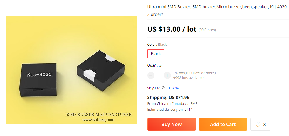
At higher cost I notice that there also exists a KLJ-4020, which is 4mmx4mmx2mm: https://www.aliexpress.com/item/2251832613970385.html?spm=a2g0o.detail.1000060.1.58582227hEwQ40&gps-id=pcDetailBottomMoreThisSeller&scm=1007.13339.274681.0&scm_id=1007.13339.274681.0&scm-url=1007.13339.274681.0&pvid=6e57d5b5-3669-4301-96cd-4254603eb5f8&_t=gps-id:pcDetailBottomMoreThisSeller,scm-url:1007.13339.274681.0,pvid:6e57d5b5-3669-4301-96cd-4254603eb5f8,tpp_buckets:668%232846%238110%231995&pdp_ext_f={"sku_id"%3A"66402727672"%2C"sceneId"%3A"3339"}&pdp_npi=2%40dis!USD!!13.0!13.0!!!!%40210323b116559355333711431e5503!66402727672!rec
-
@alphaHotel said in Most reliable "best" radio:
@NeverDie said in Most reliable "best" radio:
I've looked for tiny piezo's that could maybe do this, but they all seem to be different degrees of large. I know it should be possible to be tiny, becaue, for example, a digital wristwatch is able to make audible beeps. On the other hand, after looking at some teardowns, I guess digital watches uses piezo disks that are at least 1/2" in diameter. Hmmmm.... Is that really as small as it gets? Anyone here know? What about hearing aids? Surely they have something smaller. The smallest thing I've found so far has been this: https://owolff.com/page140.aspx?recordid140=534&output=pdf&delay=3000&margin=1cm which is 5mm in diameter. So, I guess forget mounting anything directly to the PCB board: wired discs are the way it's done apparently and then just tuck it somewhere inside the project enclosure.
I found these recently: https://www.cuidevices.com/micro-buzzers. Digikey seems to carry them but the smallest was listed as "0 quantity in stock" (https://www.digikey.ca/en/product-highlight/c/cui/micro-buzzers). The 4mm square version was available but of course that's just my local digikey, YMMV.
Adafruit's Clue device uses the KLJ-5030, which is 5mmx5mmx3mm: https://www.aliexpress.com/item/2251832675250640.html?spm=a2g0o.productlist.0.0.4ef473807sKXlG&algo_pvid=a8ed0732-081a-414b-8b9a-5745c9f7e7ff&algo_exp_id=a8ed0732-081a-414b-8b9a-5745c9f7e7ff-1&pdp_ext_f={"sku_id"%3A"65468584514"}&pdp_npi=2%40dis!USD!!47.0!47.0!!!!%402101e9d016559352842771526eafc4!65468584514!sea
At higher cost I notice that there also exists a KLJ-4020, which is 4mmx4mmx2mm: https://www.aliexpress.com/item/2251832613970385.html?spm=a2g0o.detail.1000060.1.58582227hEwQ40&gps-id=pcDetailBottomMoreThisSeller&scm=1007.13339.274681.0&scm_id=1007.13339.274681.0&scm-url=1007.13339.274681.0&pvid=6e57d5b5-3669-4301-96cd-4254603eb5f8&_t=gps-id:pcDetailBottomMoreThisSeller,scm-url:1007.13339.274681.0,pvid:6e57d5b5-3669-4301-96cd-4254603eb5f8,tpp_buckets:668%232846%238110%231995&pdp_ext_f={"sku_id"%3A"66402727672"%2C"sceneId"%3A"3339"}&pdp_npi=2%40dis!USD!!13.0!13.0!!!!%40210323b116559355333711431e5503!66402727672!rec
@NeverDie said in Most reliable "best" radio:
Adafruit's Clue device uses the KLJ-5030, which is 5mmx5mmx3mm:
At higher cost I notice that there also exists a KLJ-4020, which is 4mmx4mmx2mmYikes! :flushed: Watch out for those shipping costs. Check my math, 4mm x 4mm x 2mm x 20 pcs = 640 cubic mm = 0.640 cubic cm = 0.0391 cubic inches, from China for $72 shipping? They must weigh a ton (or a tonne). LOL! :joy:
Seriously though, good find! I think I'll keep shopping around for a better price though. :grinning:
-
@alphaHotel said in Most reliable "best" radio:
UPDATE:
I've created a Github repo for my version of the nRF24L01 adapter board.
Thanks for the version. I have made a few tweaks to your version. I don't have an openhardware account, yet, but will make one when I have the time. In the meanwhile below are the pictures of my changes. In words:
- I shrank the frame of the board to minimize the interference with the TestPlatform neighboring pins
- rerouted two traces to make the ground plane cleaner
- moved some components as needed
@Larson said in Most reliable "best" radio:
I shrank the frame of the board to minimize the interference with the TestPlatform neighboring pins
Nice! How wide is that VCC trace/plane at its narrowest point now?
If you got it from Github, are you able to send me a pull request?
-
@NeverDie said in Most reliable "best" radio:
Adafruit's Clue device uses the KLJ-5030, which is 5mmx5mmx3mm:
At higher cost I notice that there also exists a KLJ-4020, which is 4mmx4mmx2mmYikes! :flushed: Watch out for those shipping costs. Check my math, 4mm x 4mm x 2mm x 20 pcs = 640 cubic mm = 0.640 cubic cm = 0.0391 cubic inches, from China for $72 shipping? They must weigh a ton (or a tonne). LOL! :joy:
Seriously though, good find! I think I'll keep shopping around for a better price though. :grinning:
@alphaHotel said in Most reliable "best" radio:
@NeverDie said in Most reliable "best" radio:
Adafruit's Clue device uses the KLJ-5030, which is 5mmx5mmx3mm:
At higher cost I notice that there also exists a KLJ-4020, which is 4mmx4mmx2mmYikes! :flushed: Watch out for those shipping costs. Check my math, 4mm x 4mm x 2mm x 20 pcs = 640 cubic mm = 0.640 cubic cm = 0.0391 cubic inches, from China for $72 shipping? They must weigh a ton (or a tonne). LOL! :joy:
Seriously though, good find! I think I'll keep shopping around for a better price though. :grinning:
Yeah, the price is awful. I only linked it as an example. Looking a bit harder, I see they can be had for $1.53 each from a more reliable source: https://www.lcsc.com/product-detail/Buzzers_KELIKING-KLJ-4020_C556936.html The other thing to be wary regarding it is that the manufactures website says is only audible within a 0.5 to 1m range, which, if true, would be pathetically weak.
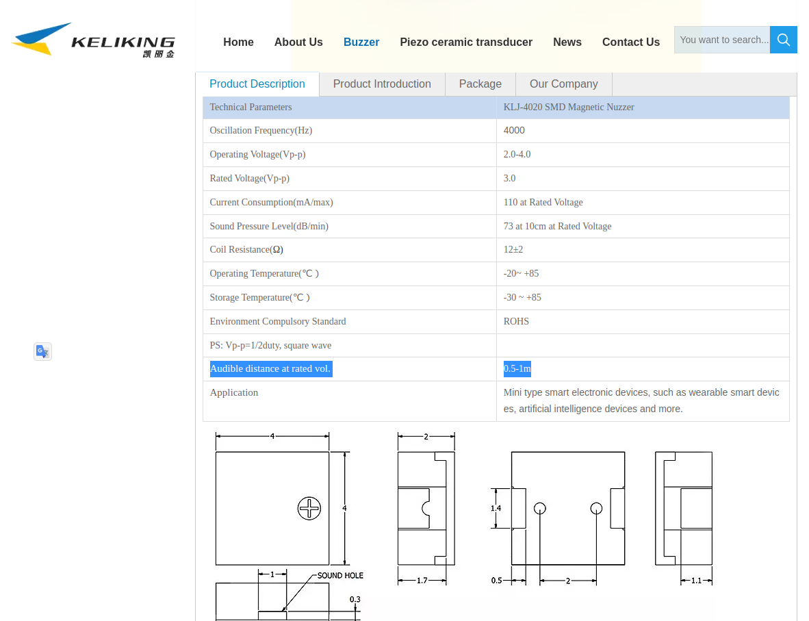
So, it has me thinking "close but no cigar."In comparison, having heard it myself, the KLJ-5030 is reasonably loud I would say.
-
Looks as though FUET has some good low-priced alternative buzzers:
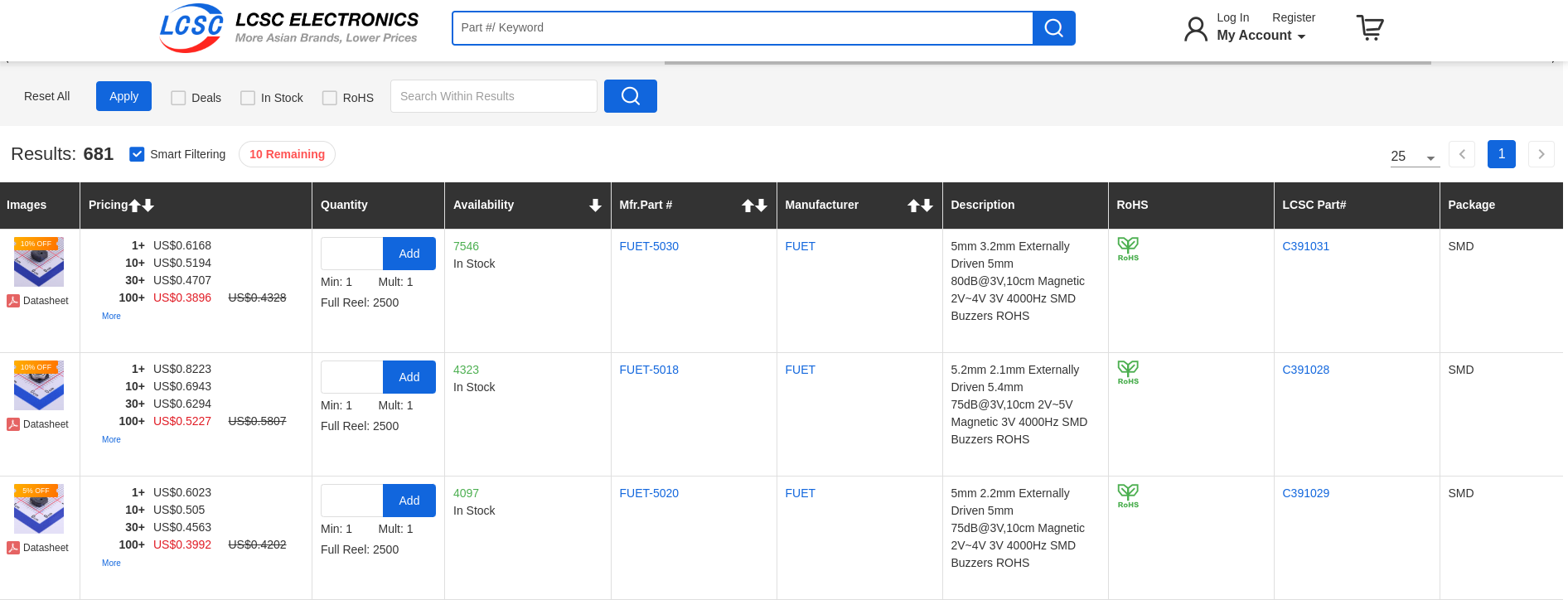
It must be something about the physics of buzzers that the thinnner they get in these small packages, the quieter they are. -
@Larson said in Most reliable "best" radio:
I shrank the frame of the board to minimize the interference with the TestPlatform neighboring pins
Nice! How wide is that VCC trace/plane at its narrowest point now?
If you got it from Github, are you able to send me a pull request?
@alphaHotel said in Most reliable "best" radio:
Nice! How wide is that VCC trace/plane at its narrowest point now?
KiCad tells me the narrowest VCC trace is about 0.045" (1.1 mm). I think the conventional 0.5 oz. copper is the common underlayment thickness. Is it too narrow? The return path is much narrower (Pin 1 nRF24L01). Does that matter?
@alphaHotel said in Most reliable "best" radio:
If you got it from Github, are you able to send me a pull request?
Yes, I think I got your version from Github. I will learn how to send a pull request. Cool, so this is how collaboration works? I'm new to this.