Most reliable "best" radio
-
@NeverDie said in Most reliable "best" radio:
Exactly which type of guitar strings do you buy that work the best? i.e. do you try to match the castellation diameter with the diameter of the string?
The brand is D’addario, I think. It measures 22 mills, and yes, I was trying to fit the diameter of the castellation. Looking online I see there are many different types, but I just asked for high carbon steel at the local music store.
@NeverDie said in Most reliable "best" radio:
Also, regarding your layout for them on the PCB, how do you decide where to position them? i.e. do you use a formula or something, or do you eyeball it and take a WAG?
It was a calculated WAG, but it worked. I wanted the rows of vias to be about 10 to 20 mills closer than the radio’s two rows of castellated pockets. The distance between the radio's castellated surfaces measures 616.5 mills. The distance between the via centers is 622.0 mills. Subtracting the 23-mill hole diameter would result in the via surface-to-surface distance on the board of 599 mills. The 17.5 mill difference (616.5 - 599) means the radio would not be able to slide all the way to the bottom. When engaged, the radio slides down within 1/4 inch of the board while the springs tops splay outward slightly.
@NeverDie said in Most reliable "best" radio:
And how do you keep them perpendicular to your PCB while you solder them?
You are asking all the right questions. Since OSH Park gave me 3 boards, I used one at each end of the wire. I think I used some blue-tac under the target board and maybe some blue-tack, or tape, to hold the place-holder board at the other end of the springs. Then I soldered top pads of the target board, flipped the assembly over, remove the target blue-tac, and soldered the bottom via surface.
To do this again, I would add SMD pads on the bottom of the board that would give more soldered rigidity to the spring base. I also had some slight alignment problems as the vias are not exactly straight. It was my first KiCad project; thank you for encouraging me to try. KiCad probably has an alignment tool. The other change I might make is to cut the wires down to about 0.5-inch, or less. The existing 0.9-inch length was helpful for assembly and soldering access, but my fear is that each of these longer wires form a potential antenna. I wouldn't change any of the other dimensions.
You are welcome to 'my' KiCad file based on your design. Is there somewhere that I can drop it. I can't do it here.
@Larson said in Most reliable "best" radio:
You are welcome to 'my' KiCad file based on your design. Is there somewhere that I can drop it. I can't do it here.
Thanks! No need to share the file as I'm not presently using RFM69 in a manner where I would need it, but your answers told me all I need to know for when any kind of similar need arises in the future. :-)
-
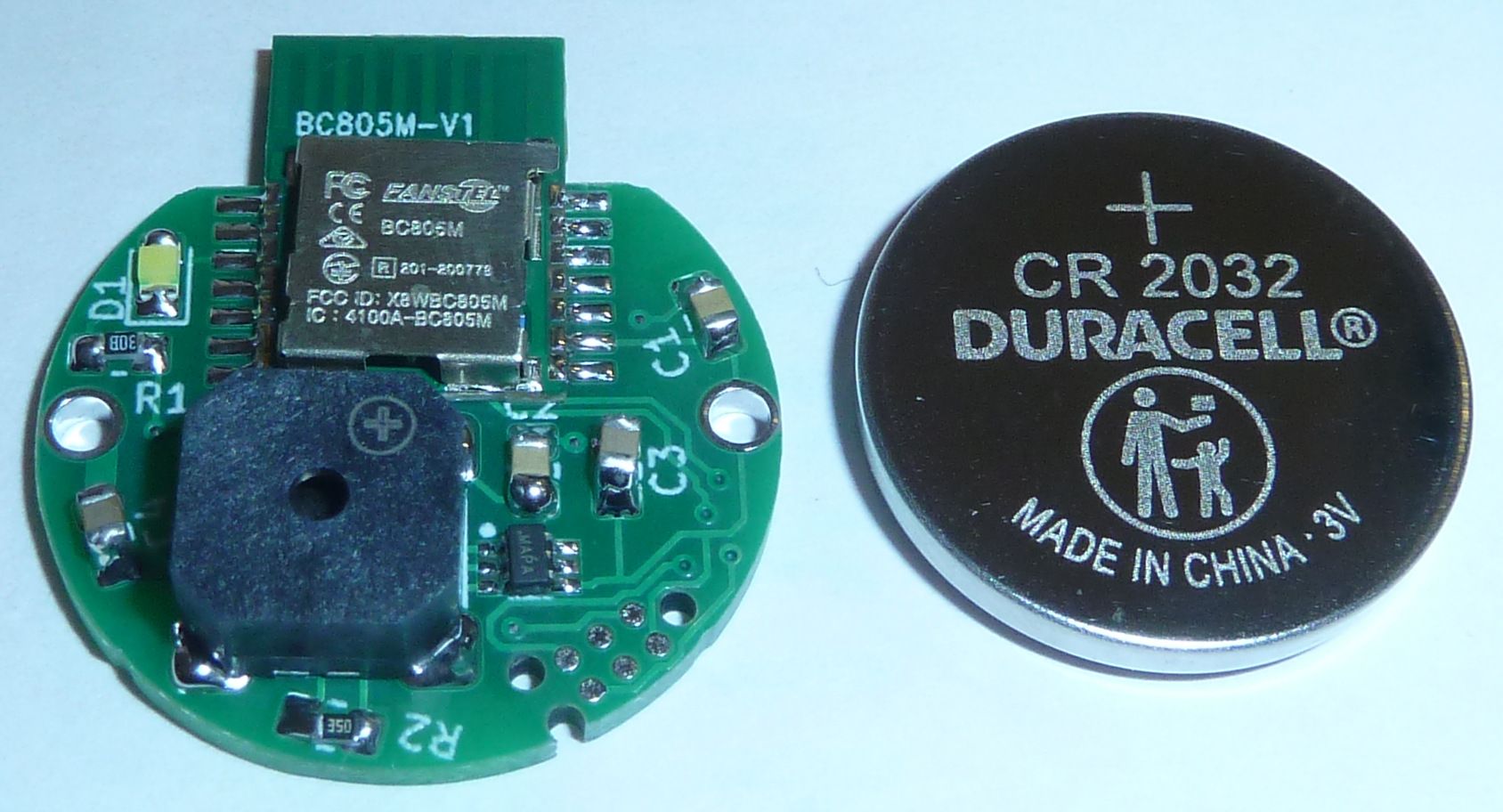
It looks as though that by rotating the TAG-CONNECT footprint a few degrees, I can fit the landing pads onto a coincell size platform without having its holes penetrate into the CR2032 connection pad.
The diameter of the PCB is 24mm. However, one of the three alignment pins might not be well supported, so maybe pushing the footprint up would be the better way to go with this. I don't see that having a hole in the GND pad of the CR2032 will make any meaningful difference. I do think that having it close to the edge, though, is probably a good idea, so that the TAG-CONNECT can hook up without hitting the metal of the coincell holder.
-
So, I think I'll opt for taking a slight bite out of the GND pad in exchange for having a sturdy connection:
-
Well, having now test driven some of the 70db and 80db buzzers, I just don't think they're loud enough to guarantee being heard under worst case scenarios. So, I found a buzzer that promises a minimum of 100dB...if powered by 150ma at 5v. Argh. So, I guess I'll be using two coincells now, plus some other support chips, in order to guarantee I can find the beacon under even adverse conditions. Maybe it's not so bad after all though, as I perhaps won't have to be concerned as much with the voltage droop that's common in CR2032's. Also, 100dB is darn loud, so that should make finding the thing by ear a lot easier.
I wonder just how long a burst of sound needs to be in order to be heard clearly? At that level of consumption, I only wanting it buzzing for the absolute minimum.
-
I sent a couple boards off to the fab, but it's now more obvious than ever before why the pro's prefer to mount a ceramic disk piezo in the case, and that's because it simply takes up too much space on the PCB. With a loud enough buzzer surface mounted on the PCB, I had to do tons of routing origami to make the parts fit. I could take another stab at it using 0402 instead of 0805 parts, but then soldering will be harder in the trade-off. For that reason, I think the short-term solution may be gluing a large surface mount buzzer to the inside top of an enclosure and then running wires from that to the PCB....except then when I screw on the top, I'd be twisting the wires. Ugh. Maybe I could pre-twist them in the wrong direction so that twisting them during the screw-on makes them untwisted when it's all finished. I'm starting to feel more like a system architect than a hobbyist. :rolling_on_the_floor_laughing: On the other hand, if I could glue the PCB to the buzzer, then it would all rotate together and life would be good. Hmmm.... Yeah, maybe that's the best option.
Another thing: it's not easy finding coincell holders that will stack two CR2032's to yield a 6v voltage. I've been down this path before on a prior occasion, and, IIRC, the solution is to stack the two coincells inside a kind of "drawer", which then slides into a clip cavity on the PCB. That does tend to add some amount of height, but it also avoids the two coincells from slipping apart and/or shorting-out against the metal of the holder. The downside is that it has a slightly bigger footprint than the non-drawer types.
On the other hand, with a flat two-cell design, there would be plenty of room for even a large SMD buzzer. Hmm.... Maybe not a bad idea.
-
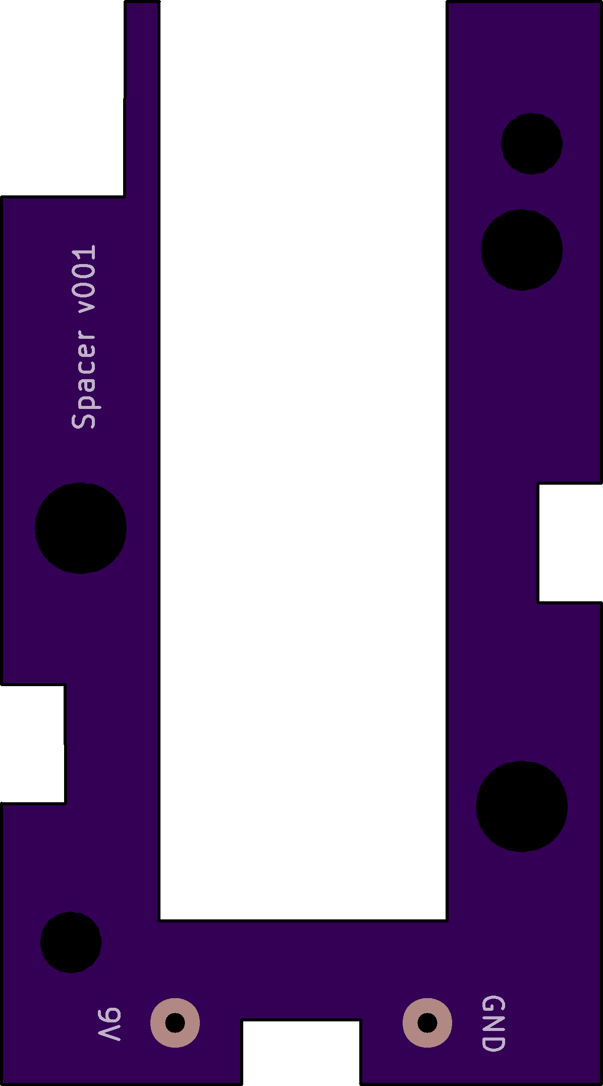
OK, I think I may have found a solution that I could mount external to the enclosure:
It promises to deliver an ear-splitting minimum of 110dB of sound pressure while drawing no more than 5ma. So, the benefits are:- Plenty loud. Even if buried in some box, I bet this could be heard.
- A voltage range of 1 to 40v, with 9v being nominal.
- Externally mounted, so not muffled by the PCB casing
- Only requires just a couple of solder pads on the PCB, which won't consume much PCB real estate.
Downside: runs at 9v for maximum effect. Datasheet doesn't indicate the sound pressure level at a lower voltage, so I'll have to buy one to test it out. Maybe this changes the form factor to more of a 9v battery size if that's what it takes. Though not ideal, that wouldn't be so bad.
Re-thinking it all now, maybe heatshrink alone would be a "good enough" enclosure that I needn't bother with a rigid enclosure? Or, better yet, since PCB's are so cheap, maybe I build an enclosure out of a stack of custom routed FR4? That would give me a lot of flexibility without having to manually fabricate something. The FR4 could give rigid protection against dings and dents. Then bolt it together through 4 corners and, presto!, a sliced stack enclosure, similar to how some raspberry pi enclosures are fabricated:

or

where FR4 could be used instead of plastic, simply because that's something a PCB house is already good at routing and shipping. Rock bottom PCB's tend to be thin, though, so this might only be economically viable for a small device, such as what I'm attempting to make. Obviously, custom 3D printing something will probably be more economical, but that comes with its own set of hassles and costs, whereas a sliced enclosure might be easy to throw together.[Edit: I just now priced it out at JLPCB, and, for instance, a 50mmx50mmx1.6mm slice with a 30mm diameter hole in the middle would cost about $0.20/slice at quantity 100. i.e. low enough to be interesting. ]
-
Reporting back: I tried it out, and that thing really is ear splitting when powered by 9 volts. It's so loud that even if I completely cover the opening, it's still loud. That's great. That means that even in a worst-case scenario where it's buried inside some sealed container, it's extremely likely I'd still be able to hear it. After all, a locator that can't be found is no good. Although it's probably overkill, when it doubt build it stout. :grinning:
Also, I ordered some PCB slices to try making an enclosure that way (as illustrated in the sliced enclosure photos above), so we'll see how that goes.
-
I discovered by accident that if I place an order with JLCPCB and then place a parts order with LCSC before the JLCPCB order ships, then LCSC will discount the shipping cost for the LCSC parts order, even though they can't actually combine shipping. Huh? This was actually my first time ordering parts from LCSC, so I'm just passing along the finding in case it might benefit anyone who might be reading this.
BTW, Intel recently predicted the chip shortage will last into 2024. :man-facepalming:
-
The strange thing about buzzers is that most of the datasheets express their SPL measured at a distance of 10cm, whereas, in contrast, most other sound sources are measured at 1 meter. Fortunately, from plugging the numbers into this conversion calculator: https://www.omnicalculator.com/physics/distance-attenuation
it turns out you can take the oddball buzzer datasheet measurements and convert them into conventional one meter SPL measurements by simply subtracting 20dB from the 10cm datasheet value. So, in reality, what the datasheet calls a "100 dB" buzzer is actually an 80db buzzer for purposes of standard comparison to most sound sources. -
The strange thing about buzzers is that most of the datasheets express their SPL measured at a distance of 10cm, whereas, in contrast, most other sound sources are measured at 1 meter. Fortunately, from plugging the numbers into this conversion calculator: https://www.omnicalculator.com/physics/distance-attenuation
it turns out you can take the oddball buzzer datasheet measurements and convert them into conventional one meter SPL measurements by simply subtracting 20dB from the 10cm datasheet value. So, in reality, what the datasheet calls a "100 dB" buzzer is actually an 80db buzzer for purposes of standard comparison to most sound sources.@NeverDie Soldier on, my friend. I love reading, but I've got nothing to add other than to report that I'm moving on to the radio portion of the barebones design. Maybe I do have something to add: I found that having JLCPCB/LCSC fabricate parts was really easy and not very expensive. The required EasyEDA design environment, I recall, linked LCSC inventory with JLCPCB quite seemlessly. As usual, for me, the learning curve took a long time. I think there were limits that wouldn't allow for exotic parts. That is not a problem for me and my simple ways. But shipping confusion did not exist as it was a combo thing. The minimum order of 5 and the single-sided fabrication were limitations that I could work with. Manually soldering SMD's is really hard and JLCPCB makes it so easy.
-
@NeverDie Soldier on, my friend. I love reading, but I've got nothing to add other than to report that I'm moving on to the radio portion of the barebones design. Maybe I do have something to add: I found that having JLCPCB/LCSC fabricate parts was really easy and not very expensive. The required EasyEDA design environment, I recall, linked LCSC inventory with JLCPCB quite seemlessly. As usual, for me, the learning curve took a long time. I think there were limits that wouldn't allow for exotic parts. That is not a problem for me and my simple ways. But shipping confusion did not exist as it was a combo thing. The minimum order of 5 and the single-sided fabrication were limitations that I could work with. Manually soldering SMD's is really hard and JLCPCB makes it so easy.
@Larson Thanks for your post. With parts getting ever more tiny, I think that would be a nice resource to leverage.
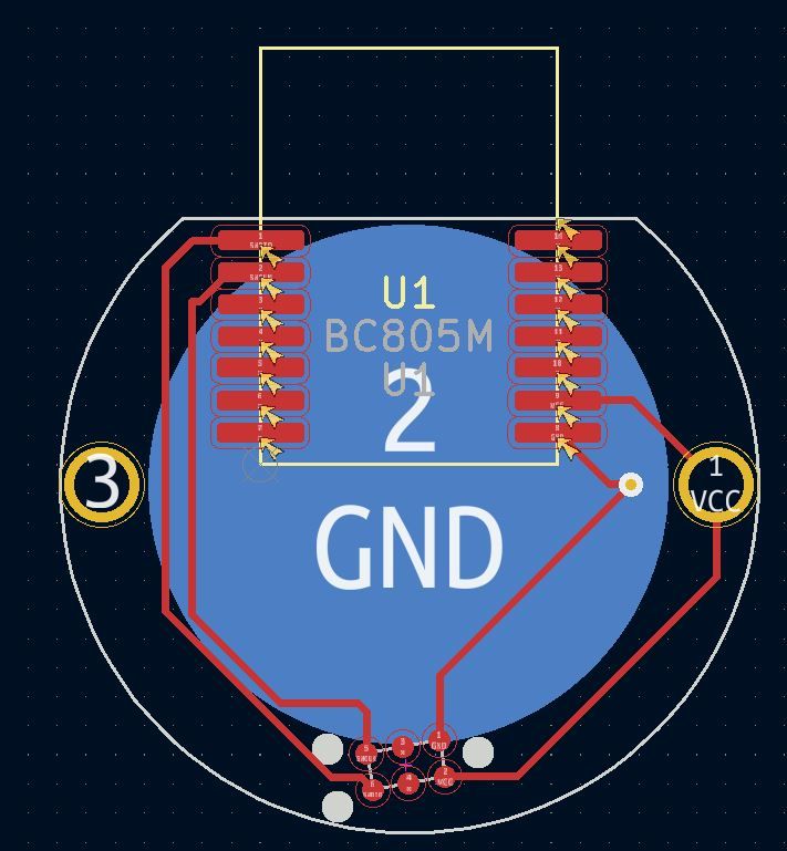
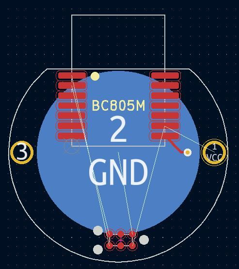
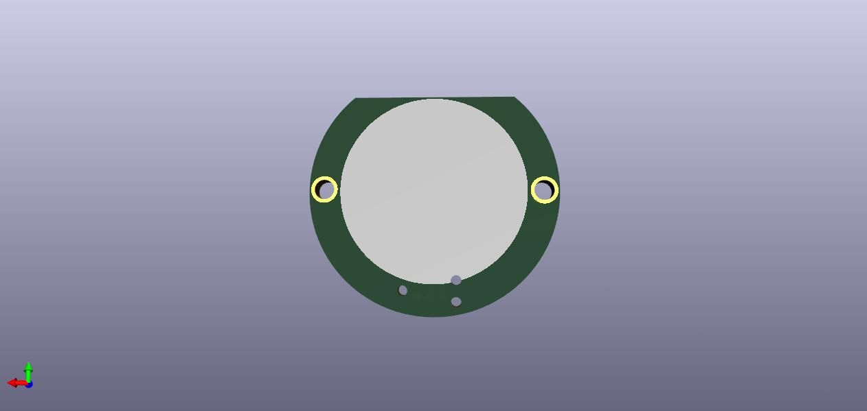
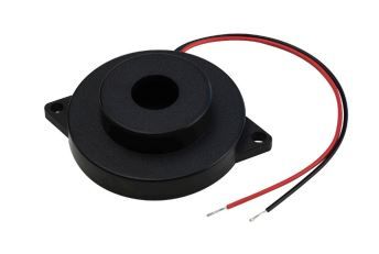
I'm presently learning more about buzzers than I ever wanted to know, but I'm having to discover the critical knowledge by experiment because the datasheets don't really adequately characterize them. In the end I think it's going to be a tradeoff between form factor, sound level, battery life, and the number of components needed to assemble the objective, as well as ease of assembly. My first design was this:
and I have a lot of alternate designs in the pipeline that I'll want to compare against it before picking a winner. Because of the buzzer dynamics, I have to actually build them in order to do a proper job of comparing them. For instance, the buzzer on this prototype is rated at 100dB at 10cm, but, as I've learned, that really only means 80dB at 1 meter if powered at 5v. But what is the SPL if powered at 3v or even 2v? Those are in the acceptable voltage range, but the datasheet doesn't say, so I have to buy buzzers and try them out in order to find out that kind of info. And it's not as straightforward as you might think, because the resonate frequency seems to change depending on the voltage. So, I have to discover that as well in order to do a proper apples-to-apples comparison.Further complicating matters is: how much current can a coincell really be counted on to deliver, especially as it ages and as its voltage drops. It turns out that answer isn't straightforward either, because it depends on how long you draw it for, and then there's a recovery period after which you can draw more current than if you don't wait for a recovery period. And how long do you need to wait, and so forth. Try figuring that out from a datasheet. That type of essential info just isn't there, and yet I need to know it if I'm going to compare the design in the photo against another design which might use, say, a CR2477 or a CR2450 or a CR123A, etc. Probably somewhere someone has built a coincell simulator to answer these types of questions. I presume that Durael or Energizer have the info but decided not to include it in their datasheets, maybe for marketing reasons.
So, to cut through all that, I'm taking the empirical route of build-and-test for a number of different design concepts, and I'll use the results to zero-in more quickly on the winner.
-
@Larson Thanks for your post. With parts getting ever more tiny, I think that would be a nice resource to leverage.
I'm presently learning more about buzzers than I ever wanted to know, but I'm having to discover the critical knowledge by experiment because the datasheets don't really adequately characterize them. In the end I think it's going to be a tradeoff between form factor, sound level, battery life, and the number of components needed to assemble the objective, as well as ease of assembly. My first design was this:
and I have a lot of alternate designs in the pipeline that I'll want to compare against it before picking a winner. Because of the buzzer dynamics, I have to actually build them in order to do a proper job of comparing them. For instance, the buzzer on this prototype is rated at 100dB at 10cm, but, as I've learned, that really only means 80dB at 1 meter if powered at 5v. But what is the SPL if powered at 3v or even 2v? Those are in the acceptable voltage range, but the datasheet doesn't say, so I have to buy buzzers and try them out in order to find out that kind of info. And it's not as straightforward as you might think, because the resonate frequency seems to change depending on the voltage. So, I have to discover that as well in order to do a proper apples-to-apples comparison.Further complicating matters is: how much current can a coincell really be counted on to deliver, especially as it ages and as its voltage drops. It turns out that answer isn't straightforward either, because it depends on how long you draw it for, and then there's a recovery period after which you can draw more current than if you don't wait for a recovery period. And how long do you need to wait, and so forth. Try figuring that out from a datasheet. That type of essential info just isn't there, and yet I need to know it if I'm going to compare the design in the photo against another design which might use, say, a CR2477 or a CR2450 or a CR123A, etc. Probably somewhere someone has built a coincell simulator to answer these types of questions. I presume that Durael or Energizer have the info but decided not to include it in their datasheets, maybe for marketing reasons.
So, to cut through all that, I'm taking the empirical route of build-and-test for a number of different design concepts, and I'll use the results to zero-in more quickly on the winner.
@NeverDie said in Most reliable "best" radio:
because the resonate frequency seems to change
Ahhh, I have something to offer. I remember way back when playing with piezo buzzers (something that is part of my mole project and in use today unfortunately) I remember incrementally changing the PWM frequency and duty cycle in the loop. I may be off base because I really don't understand what you are doing. But I remember that there is a sweet spot (resonant frequency, perhaps) where the sound would just pop. I've seen this in vocal quartets too (we are talking humans) when they hit some vibe some kind of God's amplifier gets invoked. It is really cool unless one has hyperaccousis, as I do. So I run an hide, but marvel at the science.
@NeverDie said in Most reliable "best" radio:
compare the design in the photo against another design which might use, say, a CR2477 or a CR2450 or a CR123A, etc. Probably somewhere someone has built a coincell simulator to answer these types of questions.
During dev, I try to overpower with big batteries, or lines to sort it all out before playing with the smaller cells. Understand the demands first, then find the cell that can deliver. The LIR2450 seemed to deliver a good punch of curent that can carry radio transmission peaks of a ESP8266, 400uF caps helped. Nice thing is that you can control the timing of the peak audio with any other peak load... like a radio or something and prevent an overload.
-
@NeverDie said in Most reliable "best" radio:
because the resonate frequency seems to change
Ahhh, I have something to offer. I remember way back when playing with piezo buzzers (something that is part of my mole project and in use today unfortunately) I remember incrementally changing the PWM frequency and duty cycle in the loop. I may be off base because I really don't understand what you are doing. But I remember that there is a sweet spot (resonant frequency, perhaps) where the sound would just pop. I've seen this in vocal quartets too (we are talking humans) when they hit some vibe some kind of God's amplifier gets invoked. It is really cool unless one has hyperaccousis, as I do. So I run an hide, but marvel at the science.
@NeverDie said in Most reliable "best" radio:
compare the design in the photo against another design which might use, say, a CR2477 or a CR2450 or a CR123A, etc. Probably somewhere someone has built a coincell simulator to answer these types of questions.
During dev, I try to overpower with big batteries, or lines to sort it all out before playing with the smaller cells. Understand the demands first, then find the cell that can deliver. The LIR2450 seemed to deliver a good punch of curent that can carry radio transmission peaks of a ESP8266, 400uF caps helped. Nice thing is that you can control the timing of the peak audio with any other peak load... like a radio or something and prevent an overload.
@Larson said in Most reliable "best" radio:
But I remember that there is a sweet spot (resonant frequency, perhaps) where the sound would just pop.
Yup, I've noticed the same, if by "pop" you mean becomes noticeably louder. It's not free though, as the current consumption also hits a peak at that frequency, which is yet another way to identify where the "pop" happens. But, anyway, yes, I agree, that is the magic sweet spot, and it's absolutely worth the extra current.
-
I ran into a "gotcha" with the larger piezo buzzer. It turns out that they have high enough inherent capacitance that you need either a resistor or something else to "drain" them during the off-phase of a square wave. Otherwise, the sound is minuscule. According to my Fluke multimeter, the large piezo's have only about 24nF of capacitance. I haven't yet checked with an LCR meter to confirm.
It turns out you can use an inductor instead of a resistor and setup a resonant circuit, which is more energy efficient than just using a resistor. So, I may try that, even though it's a more complex circuit to construct, because this way it will also increase the voltage (and hence volume) of the buzzer:

https://www.digikey.com/en/articles/design-techniques-to-increase-a-piezo-transducer-buzzer-audio-outputWhat's also interesting is that for buzzer's with a feedback terminal, you can use a simple circuit to automagically drive them at their resonate frequency:
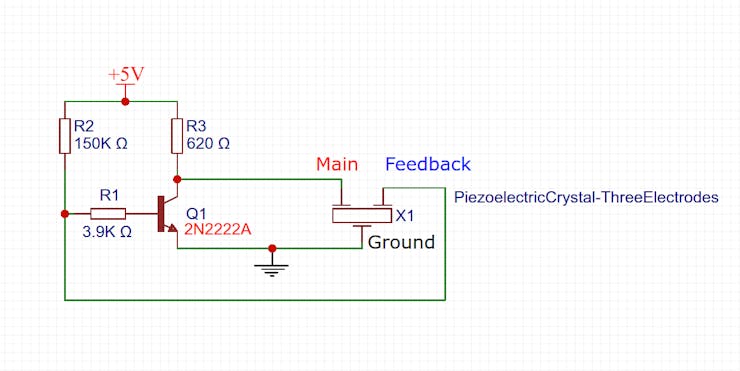
https://www.hackster.io/taunoerik/self-drive-piezo-buzzer-e9786f
Evidently this also serves the purpose of "draining" the buzzer without using a resistor directly across Main and Ground.Well, by trial and error, I've determined that it takes about a 100 ohm resistor to adequately "drain" the buzzer during the low phase of a square wave. Assuming 3V, that means 300ma wasted current during the high phase. On it's face, that seems excessive.
The small buzzers seem to neither need nor benefit from these drain resistors. I guess their inherent capacitance is simply too low to matter.
[Reporting back: I tried out the self driving buzzer circuit, and 1. it works at higher voltages of around 9-10v, and 2. even then it isn't as loud as a proper square wave at 3v. So... I'm nixing that idea. Besides, it's rather fiddly as to getting the component values just right in order to work, and who knows how much variation there might be in the manufactured piezo buzzers.]
-
Fun to see what hobbyists can achieve when they stick to it long enough:
https://www.youtube.com/watch?v=SH3lR2GLgT0 -
Fun to see what hobbyists can achieve when they stick to it long enough:
https://www.youtube.com/watch?v=SH3lR2GLgT0@NeverDie Yep, that rocket stuff, and that dedication-to-task stuff, is pretty cool. Thanks for sharing - very inspirational.
At a more modest level ... I received the Atmega 328P programming harness/clamp you recommended long ago. Nice. And your barebones board loaded with my RFM69HCW jig are working nicely. Also received: a bunch of your suggested radios and the carrying boards. Time, I need time. Can't thank you and @alphaHotel enough for the encouragement. I look forward to reporting if only to chronical for my own record and possible use for others.
I hope it doesn't take me 7 years, but it may. Now all I need is a bunch of 48 hour days.
-
What I've learned lately about buzzers, through experimentation, is that to get maximum loudness I need to drive a buzzer within about plus-or-minus 5Hz of its optimum resonance frequency. More than that and the loudness drops off precipitously. Unfortunately, manufacturing variance is probably more than plus-or-minus 5Hz, so that's a potential problem. The voltage supplied on the feedback pin of a piezo is only around 50mv, which is too low for an for an MCU to measure accurately without some kind of extra circuitry to help. It would be nice if the system could self-calibrate the driving frequency to match the inherent resonance frequency of the buzzer.
Meanwhile, I'm switching over to an H-bridge for driving buzzers, because an H-bridge not only efficiently drains the charge that builds up on the piezo buzzer but it also effectively doubles the peak-to-peak voltage seen by the buzzer. At these low voltages, more apparent voltage means more loudness.
When I started this project, I really didn't expect that the buzzer part of it would turn-out to require as much attention as it has! Sure, getting some amount of loudness is not a problem, but really maximizing loudness at these low voltages, while maintaining a tiny footprint and ease-of-assembly, isn't as easy as you'd think a priori.
@NeverDie said in Most reliable "best" radio:
It would be nice if the system could self-calibrate the driving frequency to match the inherent resonance frequency of the buzzer.
Perhaps an initialization User Interface selection? If the big picture is arranged and the region is only 5 Hz, then maybe a centeral default with an user option would be acceptable. Start slow, then rise in 0.25 Hz increments? If the user doesn't repond, then the default is mid-range. As in life, you can only help people so far. I think my mother tried to tell me that once.
Caveat User (Emptor).
-
@NeverDie said in Most reliable "best" radio:
It would be nice if the system could self-calibrate the driving frequency to match the inherent resonance frequency of the buzzer.
Perhaps an initialization User Interface selection? If the big picture is arranged and the region is only 5 Hz, then maybe a centeral default with an user option would be acceptable. Start slow, then rise in 0.25 Hz increments? If the user doesn't repond, then the default is mid-range. As in life, you can only help people so far. I think my mother tried to tell me that once.
Caveat User (Emptor).
@Larson said in Most reliable "best" radio:
@NeverDie said in Most reliable "best" radio:
It would be nice if the system could self-calibrate the driving frequency to match the inherent resonance frequency of the buzzer.
Perhaps an initialization User Interface selection? If the big picture is arranged and the region is only 5 Hz, then maybe a centeral default with an user option would be acceptable. Start slow, then rise in 0.25 Hz increments? If the user doesn't repond, then the default is mid-range. As in life, you can only help people so far. I think my mother tried to tell me that once.
Caveat User (Emptor).
You mean make it user selectable?
I'm toying with the idea of an initial calibration using equipment not on the PCB. That's how I arrived at the optimal frequency on my prototype. However, it's unpleasant listening to the frequency sweeps. Even my wife complained about it, and she was in a different room entirely. The only upside is that it's sure to work.
I found a good size for a shell, using a Govee temperature-humidity sensor:

It runs on a CR2477, so it has plenty of depth to it. Nobody seems to shell the shells though, and it would be a shame to canibalize their sensor just for the shell alone. I guess I'll have to 3D print something....