Most reliable "best" radio
-
@Larson said in Most reliable "best" radio:
@NeverDie said in Most reliable "best" radio:
It would be nice if the system could self-calibrate the driving frequency to match the inherent resonance frequency of the buzzer.
Perhaps an initialization User Interface selection? If the big picture is arranged and the region is only 5 Hz, then maybe a centeral default with an user option would be acceptable. Start slow, then rise in 0.25 Hz increments? If the user doesn't repond, then the default is mid-range. As in life, you can only help people so far. I think my mother tried to tell me that once.
Caveat User (Emptor).
You mean make it user selectable?
I'm toying with the idea of an initial calibration using equipment not on the PCB. That's how I arrived at the optimal frequency on my prototype. However, it's unpleasant listening to the frequency sweeps. Even my wife complained about it, and she was in a different room entirely. The only upside is that it's sure to work.
I found a good size for a shell, using a Govee temperature-humidity sensor:

It runs on a CR2477, so it has plenty of depth to it. Nobody seems to shell the shells though, and it would be a shame to canibalize their sensor just for the shell alone. I guess I'll have to 3D print something....@NeverDie said in Most reliable "best" radio:
The only upside is that it's sure to work.
Very, very funny. Fell off my chair, funny. I had a similar experience with testing buzzers only I failed to recognize the upside/benefit. I ended up putting a switch on the speaker effect to maintain domestic tranquility.
Yes, frequency user selection was my thought. It sounded like the mV range detection/optimization was too complicated. If the design gets close enough to the expected range, then punt to the user for fine tuning.
Shells: Unless a resonant cavity is important, how about a simple tic-tac container with a pre-drilled speaker hole and some hot glue? Maybe a pezz container, if they make those any more? Even a Gatorade bottle cap filled with epoxy might work (use cellophane to cover/embed the mechanical parts of the speaker.) Failure has taught me many things, and this is one of them.
-
Good suggestion on using a tic-tac container. It never would have dawned on me. Too bad I'm on a Keto diet, but I guess I could give the tic-tacs to my son, who doesn't need to diet.
I may have spoke too soon that the nRF52 isn't sensitive enough to read the feedback voltage precisely enough. It turns out to have a 0.6v internal voltage reference, and it has a 12-bit ADC, so in theory it could measure in increments of as little as 0.6v/4096=0.146millivolts. Is that good enough? I really don't know, but I'm going to give it a try. The closer the piezo gets to resonance, the more the feedback voltage should shoot up. I'd be counting on it shooting up by a lot when it hits resonance. So, I just now uploaded the files to a fab for a PCB which can do those measurements, and hopefully I'll receive it in about a week. :-)
-
Check out the Hammond 1551V1gY (vented) or 1151SNAP1GY (unvented).
They look like they are about the same size. I've been using the vented ones for temp/humidity sensors. Not as ugly as most project boxes.@nagelc said in Most reliable "best" radio:
Check out the Hammond 1551V1gY (vented) or 1151SNAP1GY (unvented).
They look like they are about the same size. I've been using the vented ones for temp/humidity sensors. Not as ugly as most project boxes.Good find! I like the vented ones, as it look like they would let out a lot of sound.
-
Check out the Hammond 1551V1gY (vented) or 1151SNAP1GY (unvented).
They look like they are about the same size. I've been using the vented ones for temp/humidity sensors. Not as ugly as most project boxes.@nagelc said in Most reliable "best" radio:
Check out the Hammond 1551V1gY (vented) or 1151SNAP1GY (unvented).
They look like they are about the same size. I've been using the vented ones for temp/humidity sensors. Not as ugly as most project boxes.@nagelc I ordered the white version of the vented model you referred to so that I can give it an up-close looky-loo. I also found an interesting "similar but different" vented enclosure from New Age Enclosures, though at twice the price, which I also ordered for comparison:

https://www.mouser.com/ProductDetail/789-P1A-151510
With benefit of hindsight, maybe I should have started to look at possible enclosures from the get-go, because, depending on what's available, that may very well determine what form factors are even worth considering. :face_palm: i.e. the project will end-up needing to fit the enclosure, probably not the other way around. -
I think I may now finally understand the purpose of the optional S0, LENGTH, and S1 fields in the nRF52 packet frame. The datasheet gives very little insight into them, so I had previously disabled those fields just to avoid the topic altogether because it seemed so obscure. However, in trying to figure out how to send/receive packets between an nRF52 and an old-style nRF24L01+, the puzzle finally makes sense: they are there to either 1. provide a means of compatability with the nRF24L01's Enhanced Shockburst, which puts a 9-bit field in the middle of the frame:
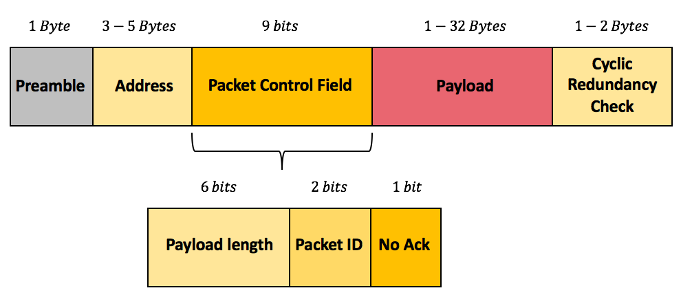
or 2. allows you to roll-your-own super Enhanced Shockburst with extra bits (in which case standard nRF24L01P ESB compatibility goes out the window). Well, for a host of reasons, I think nRF24L01p compatability is worth enduring an extra 9 bits of airtime, so I'll go that route and configure the nRF52 accordingly now that I've inferred what those fields are meant for. :face_with_cowboy_hat: -
I like your ideas. Is there a circuit for common mode rejection? It would be worth exploring. And using a test port for different pull-up resistors, better yet a variable resistor, would allow for testing.
-
Reporting back on the E01-2G4M27D radio's that I had referenced earlier. For those who don't remember, these are nRF24L01P radios that have been upgraded to use a 27dBa PA and, allegedly, other higher quality components (https://www.ebyte.com/en/product-view-news.aspx?id=450). 27dBa = 0.5 watt. For comparison, the maximum Tx power of a plain nRF24L01 is just 0dB. I had occasion to try them out today, and they appear to perform extremely well, even at 2mbps while transmitting over the worst-case transmission path in my house that I've been using to test all the radios on.
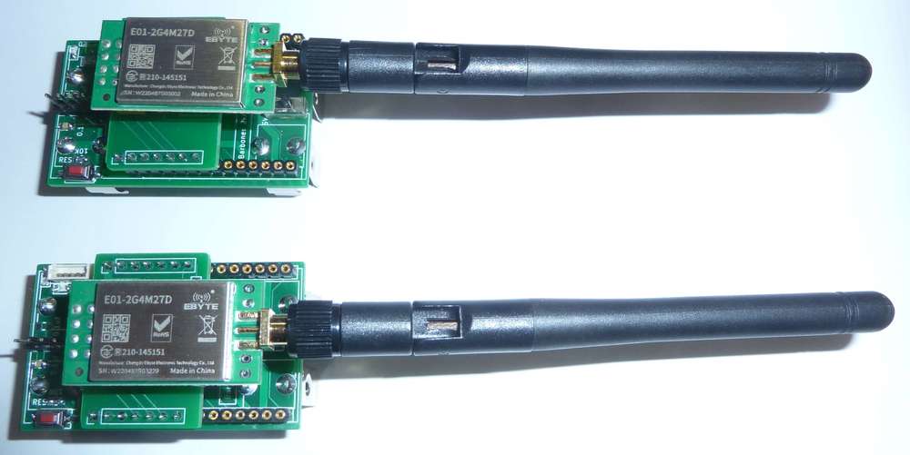
I'd venture to say that in terms of reliably getting a packet through to its destination, they outperform all other enhanced nRF24L01P's that I've ever tried previously. If you opt to try them on the test platform, as I have done, I recommend you upgrade your BoB capacitor to 100uF or 200uF, because 10uF doesn't seem to be enough when transmitting from somewhat weak batteries. Nonetheless , 10uF is sufficient if powering it from a really stiff power source. Ironically, they vastly outperform the 2.4Ghz LoRa radios that got me started on this whole mini-blog in the first place.Looks as though you can buy them on sale at $4.59 each: https://www.aliexpress.com/item/2255800350626109.html?gatewayAdapt=4itemAdapt
No, they don't come with the antennas. You'll have to source those separately.I'd say the main downside to these modules is that there does not appear to be any way to dial-down the transmission power, so that you only use as much power as you really need to fit your circumstances. There's no reason that such a module couldn't be designed and built (just as the RFM69HW allows), but, AFAIK, there aren't any on the market like that for the nRF24L01P. It's such an obvious enhancement that I'm surprised none of the vendors have offered it, even if it requires extra pins. Maybe someone reading this knows of one? If so, please post.
-
:face_palm: Doh! It just occured to me that rather than being a fixed output power, maybe these modules actually do have adjustable gain via adjusting the power output of the nRF24L01P:
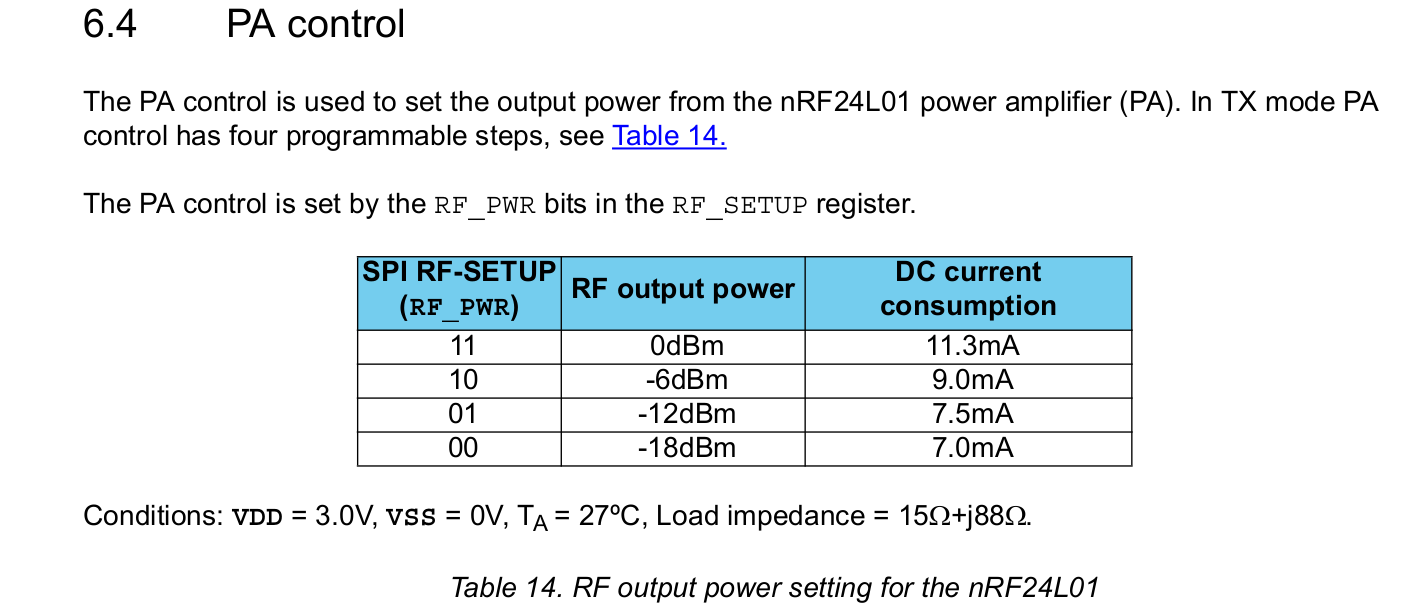
That would perhaps mean that you could adjust the power output to be 27dB minus 18dB = 9dB? i.e. they effectively offer a gain of 27dB to whatever output power your radio chip already has? Is that how PA's work? Or, instead, would it just be blasting out mostly noise at 27dB if I were to set the nRF24L01P's output power to -18dBm? I'm guessing the former and not the latter, but unfortunately I don't have any radiated RF power measuring equipment that might tell me the answer. Anyone know? Perhaps measuring the current consumed during transmission would tell the tale, as one could infer the output power from that. Hmmmm...... Worth a try. Might be able to approximate the answer from that. If it turns out that they are adjustable in this manner, then I would think they are pretty awesome as a default "go to" module for just about anything. i.e. you'd have good communication even on the low-end of 9dB, but you would also have plenty of headroom to notch it up to a higher output power if it were truly necessary to cover whatever contingency you might run into, provided it remains within the legal limits of whatever your jurisdiction is.
I once tried (and reported on) a 4watt 2.4Ghz amplifier that you can buy on amazon, and it had a "sweet spot" for input power that it could amplify from, but below that sweet spot it didn't do much good at all. Perhaps that's a more accurate model of how this works in real life?
Looking at the manual, it does say the output power is multi-level software adjustable, so there's hope. https://www.ebyte.com/en/downpdf.aspx?id=450 I don't see that it offers any hints beyond that though.
-
Well, attempting to answer my own question above, here is the power profile of the E01-SG4M27D when the nRF24L01P is set to 0db (plus whatever power the PA on module boosts that to):
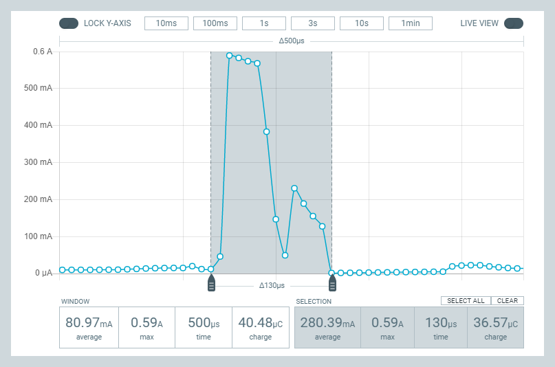
Here it is when the nRF24L01P is set to -18dBm ( (plus whatever power the PA on module boosts that to):
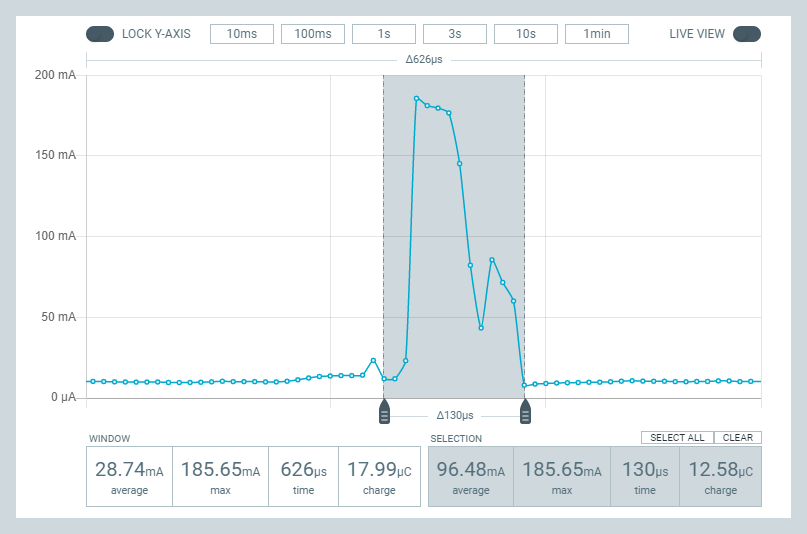
So, it looks as though the latter is the current is roughly 1/3 of the former, and since the voltage is the same, that would imply that the power is about 1/3 also. However, if my earlier theory was right, then the second chart should be showing a maximum of about 7.4mw, as compared to the theoretical 500mw of the first chart.
So, really, neither chart makes much sense. 3.3v x 580ma = 1.9 watts and 3.3v x 180ma = 0.594 watts. Well, I guess that's wrong if the radio module converts the 3.3v to a lower voltage for running the radio at via an LDO, which means it disappates the difference as heat. Still, the ratio between high and low Tx power is something like 3 to 1, whereas in theory it should be more like 67 to 1. So, I really don't know what to make of all that, other than the PA doesn't have much dynamic range to it. Does that extra power at the low end translate into proportioinately more radiated RF? I have no way of knowing, as this is the limit of what I can test with the equipmet that I have. I'd need something which can measure actual radiated RF.
This guy demonstrates how that might be done:
https://www.youtube.com/watch?v=FVaiWzJSvNUIn a nutshell, it would require both the power meter and, in this intance, an attenuator to go along with it.
I suppose an alternate, non-elegant way to solve the problem would be to have an array of different nRF24L01 modules, each optimized for a different power level. Then, by selecting the right CE pin, you could switch among them for the desired power level for a transmission. Not completely outlandish if size doesn't matter so much, because nRF24L01P modules, in whatever flavor, are generally fairly cheap--perhaps cheaper than buying the $80+ worth equipment needed to measure RF power that would probably be only one-time use. So, for a gateway, that might be a possibility. For a sensor node, probably not.
-
I think I may now finally understand the purpose of the optional S0, LENGTH, and S1 fields in the nRF52 packet frame. The datasheet gives very little insight into them, so I had previously disabled those fields just to avoid the topic altogether because it seemed so obscure. However, in trying to figure out how to send/receive packets between an nRF52 and an old-style nRF24L01+, the puzzle finally makes sense: they are there to either 1. provide a means of compatability with the nRF24L01's Enhanced Shockburst, which puts a 9-bit field in the middle of the frame:
or 2. allows you to roll-your-own super Enhanced Shockburst with extra bits (in which case standard nRF24L01P ESB compatibility goes out the window). Well, for a host of reasons, I think nRF24L01p compatability is worth enduring an extra 9 bits of airtime, so I'll go that route and configure the nRF52 accordingly now that I've inferred what those fields are meant for. :face_with_cowboy_hat:@NeverDie said in Most reliable "best" radio:
I think I may now finally understand the purpose of the optional S0, LENGTH, and S1 fields in the nRF52 packet frame. The datasheet gives very little insight into them, so I had previously disabled those fields just to avoid the topic altogether because it seemed so obscure. However, in trying to figure out how to send/receive packets between an nRF52 and an old-style nRF24L01+, the puzzle finally makes sense: they are there to either 1. provide a means of compatability with the nRF24L01's Enhanced Shockburst, which puts a 9-bit field in the middle of the frame:
or 2. allows you to roll-your-own super Enhanced Shockburst with extra bits (in which case standard nRF24L01P ESB compatibility goes out the window). Well, for a host of reasons, I think nRF24L01p compatability is worth enduring an extra 9 bits of airtime, so I'll go that route and configure the nRF52 accordingly now that I've inferred what those fields are meant for. :face_with_cowboy_hat:It worked! :smile: :smiley: :slightly_smiling_face: Well, sort-of. I have it working using the five byte address 0xE7E7E7E7E7, which dodges the question of how the address bytes are ordered over the air in one scheme versus the other. That's the next puzzle to solve. You might think this would be easy to solve, as I did, but so far not.
Here's part of what's weird (this is taken from the nRF52 datasheet):
Can you see the disconnect? On the nRF52 the LENGTH field comes in the middle of the 9 bits, whereas on the nRF24L01 ESB it comes at the front of the 9 bits.
Also, I haven't been able to get any non-repeating address to work yet. e.g. x0101010101 works, and so does 0xE7E7E7E7E7, but that's a rather limiting type of address to rely upon, though I suppose I could live with it if I had to. Go figure.
-
@NeverDie said in Most reliable "best" radio:
I think I may now finally understand the purpose of the optional S0, LENGTH, and S1 fields in the nRF52 packet frame. The datasheet gives very little insight into them, so I had previously disabled those fields just to avoid the topic altogether because it seemed so obscure. However, in trying to figure out how to send/receive packets between an nRF52 and an old-style nRF24L01+, the puzzle finally makes sense: they are there to either 1. provide a means of compatability with the nRF24L01's Enhanced Shockburst, which puts a 9-bit field in the middle of the frame:
or 2. allows you to roll-your-own super Enhanced Shockburst with extra bits (in which case standard nRF24L01P ESB compatibility goes out the window). Well, for a host of reasons, I think nRF24L01p compatability is worth enduring an extra 9 bits of airtime, so I'll go that route and configure the nRF52 accordingly now that I've inferred what those fields are meant for. :face_with_cowboy_hat:It worked! :smile: :smiley: :slightly_smiling_face: Well, sort-of. I have it working using the five byte address 0xE7E7E7E7E7, which dodges the question of how the address bytes are ordered over the air in one scheme versus the other. That's the next puzzle to solve. You might think this would be easy to solve, as I did, but so far not.
Here's part of what's weird (this is taken from the nRF52 datasheet):
Can you see the disconnect? On the nRF52 the LENGTH field comes in the middle of the 9 bits, whereas on the nRF24L01 ESB it comes at the front of the 9 bits.
Also, I haven't been able to get any non-repeating address to work yet. e.g. x0101010101 works, and so does 0xE7E7E7E7E7, but that's a rather limiting type of address to rely upon, though I suppose I could live with it if I had to. Go figure.
-
@NeverDie You are building a library. I don’t have the time to consume/enjoy it now as I’m deep in eldercare. But for sure, I’m coming back to your wonderful library to learn more – just later. Don’t interpret my silence as… indifference.
@Larson No worries. It works better with feedback from a knowledgeable audience, but... that entire audience has seemingly evaporated. Nonetheless, this rubber ducking may still have some value even under the current "everyone long gone" circumstances.

-
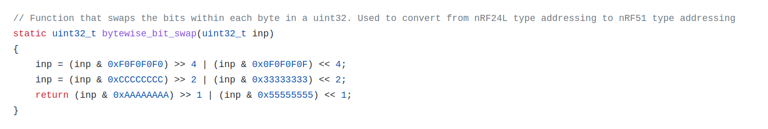
Aha! Apparently there is some kind of undocumented difference in the way addresses are represented in an nRF24L01P vs. an nRF5x. I found this address conversion function in Nordic's "micro-esb" library (https://github.com/NordicPlayground/nrf51-micro-esb/blob/master/common/micro_esb.c ) which holds promise for illuminating what that difference is:
and

Just from eyeballing it, nRF24L01P apparently transmits in the order of most significant bits first (which is undocumeneted), as compared to nRF5x, which transmits in order of least significant bits first (which is documented). Well, that would explain why xE7 (=B11100111), worked in my earlier addressing attempt, since it is the same either way.
Well, yes, though the algorithm is a two-step process. The bytewise_bit_swap function apparently reverses the ordering of bits in each byte, but leaves the bytes in the same order:
1111111111111111111111110100 -> 11110000111111111111111100101111
1111111111111111111111110011 -> 11110000111111111111111111001111
1111111111111111111111110010 -> 11110000111111111111111101001111
1111111111111111111111110001 -> 11110000111111111111111110001111
1111111111111111111111110000 -> 11110000111111111111111100001111
The radio address config section then reorders the sequence of the bytes. The net effect is the same as what I had guessed.
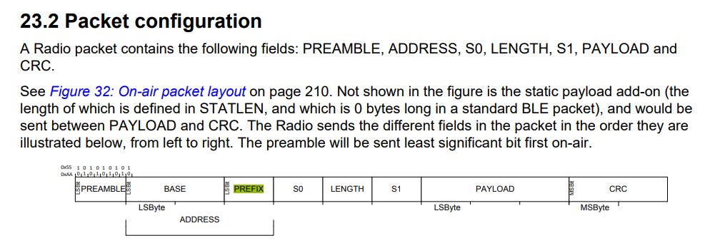
Well, this does explain why on the nRF5x, the "prefix" comes after the address section in the above diagram. My original impression had been that it was a poor choice of nomenclature.Next I need to test this new theory on the hardware and see if it works.
-
Well, attempting to answer my own question above, here is the power profile of the E01-SG4M27D when the nRF24L01P is set to 0db (plus whatever power the PA on module boosts that to):
Here it is when the nRF24L01P is set to -18dBm ( (plus whatever power the PA on module boosts that to):
So, it looks as though the latter is the current is roughly 1/3 of the former, and since the voltage is the same, that would imply that the power is about 1/3 also. However, if my earlier theory was right, then the second chart should be showing a maximum of about 7.4mw, as compared to the theoretical 500mw of the first chart.
So, really, neither chart makes much sense. 3.3v x 580ma = 1.9 watts and 3.3v x 180ma = 0.594 watts. Well, I guess that's wrong if the radio module converts the 3.3v to a lower voltage for running the radio at via an LDO, which means it disappates the difference as heat. Still, the ratio between high and low Tx power is something like 3 to 1, whereas in theory it should be more like 67 to 1. So, I really don't know what to make of all that, other than the PA doesn't have much dynamic range to it. Does that extra power at the low end translate into proportioinately more radiated RF? I have no way of knowing, as this is the limit of what I can test with the equipmet that I have. I'd need something which can measure actual radiated RF.
This guy demonstrates how that might be done:
https://www.youtube.com/watch?v=FVaiWzJSvNUIn a nutshell, it would require both the power meter and, in this intance, an attenuator to go along with it.
I suppose an alternate, non-elegant way to solve the problem would be to have an array of different nRF24L01 modules, each optimized for a different power level. Then, by selecting the right CE pin, you could switch among them for the desired power level for a transmission. Not completely outlandish if size doesn't matter so much, because nRF24L01P modules, in whatever flavor, are generally fairly cheap--perhaps cheaper than buying the $80+ worth equipment needed to measure RF power that would probably be only one-time use. So, for a gateway, that might be a possibility. For a sensor node, probably not.
@NeverDie said in Most reliable "best" radio:
I suppose an alternate, non-elegant way to solve the problem would be to have an array of different nRF24L01 modules, each optimized for a different power level.
Does the optimization mean different HW components with different RF_PWR settings? If the HW remains the same then one could incrementally change the RF_PWR level in the loop, right? Perhaps even by using two input pins one could control the RF_PWR level settings manually. The pins determine 00, 01, 10, or 11 and that gets fed to RF_PWR. That might be easier.
-
@NeverDie said in Most reliable "best" radio:
I suppose an alternate, non-elegant way to solve the problem would be to have an array of different nRF24L01 modules, each optimized for a different power level.
Does the optimization mean different HW components with different RF_PWR settings? If the HW remains the same then one could incrementally change the RF_PWR level in the loop, right? Perhaps even by using two input pins one could control the RF_PWR level settings manually. The pins determine 00, 01, 10, or 11 and that gets fed to RF_PWR. That might be easier.
@Larson said in Most reliable "best" radio:
@NeverDie said in Most reliable "best" radio:
I suppose an alternate, non-elegant way to solve the problem would be to have an array of different nRF24L01 modules, each optimized for a different power level.
Does the optimization mean different HW components with different RF_PWR settings? If the HW remains the same then one could incrementally change the RF_PWR level in the loop, right? Perhaps even by using two input pins one could control the RF_PWR level settings manually. The pins determine 00, 01, 10, or 11 and that gets fed to RF_PWR. That might be easier.
Is your two pin solution referring to picking different modules, or to somehow adjusting the Tx power on one module? Not really following what you mean there. Since all the nRF24L01 modules use SPI, what I imagined was a separate chip enable line for each one, which would make it very easy to select among them. Indeed, that's the very definition of how SPI works. Straightforward.
-
@Larson said in Most reliable "best" radio:
@NeverDie said in Most reliable "best" radio:
I suppose an alternate, non-elegant way to solve the problem would be to have an array of different nRF24L01 modules, each optimized for a different power level.
Does the optimization mean different HW components with different RF_PWR settings? If the HW remains the same then one could incrementally change the RF_PWR level in the loop, right? Perhaps even by using two input pins one could control the RF_PWR level settings manually. The pins determine 00, 01, 10, or 11 and that gets fed to RF_PWR. That might be easier.
Is your two pin solution referring to picking different modules, or to somehow adjusting the Tx power on one module? Not really following what you mean there. Since all the nRF24L01 modules use SPI, what I imagined was a separate chip enable line for each one, which would make it very easy to select among them. Indeed, that's the very definition of how SPI works. Straightforward.
@NeverDie said in Most reliable "best" radio:
two pin solution
Sorry, sometimes when I reread what I wrote, I don't understand it either.
My suggestion was to use only one radio and rotate different RF_PWR settings into the radio from the Atmega328p chip. That could be done by different means: 1. in the loop every 10 seconds or so for testing, or 2. by using GPIO pins defined as inputs, or 3. since we are talking radios, the power level could be transmitted to subject radio, read in code, and changed on the fly, or 4. any variety of other means (sensed light, temperature, vibration...)
For example, I'm looking at your barebones board right now. The radio module I'm using (RFM69HCW) is mounted on the first 8 pins of the headers that include SPI connections. Neighboring pins A0 and A1 on the barebones header are open and could be jumpered to GND (logic 0) or VCC (logic 1). The program on the 328 could sense those pins and select one of 4 power levels in the RF_PWR setting per the table you show above.
Hope that helps!
-
Reporting back regarding how to successfully transmit a packet from an nRF24L01P to an nRF5x, here's what I've confirmed (using the actual hardware) regarding the differences in how addressing is handled between the two different platforms:
Suppose the receiver address on a particular nRF52 (let us call it nRF52#1) is this:
prefix: 0x01
base-address: 0xACC01ADE
However, despite the name "prefix", we know from the datasheet that, from a temporal standpoint, when the over-the-air bits get sent, the prefix actually gets sent after the base-address. That means that if another nRF52 (let us call it nRF52#2) were transmitting an address meant to match nRF52#1, then the over-the-air bits, which are sent least-significant bit first on an nRF5x, would be sent as follows if you were writing them down left to right in temporal transmission order:
(reverse 0xACC01ADE) followed by (reverse 0x01)
Hence, from a certain twisted perspective it does make sense to call 0x01 a "prefix", because this is the same as:
(reverse 0x01ACC01ADE)So, given that, the target Tx address, from the standpoint of an nRF24L01P, concatenated together, is the very same:
(reverse 0x01ACC01ADE)
because an nRF24L01P transmits in the order of most-significant-bit first.
As it turns out, this is equivalent to:
(reverse 0xDE) (reverse 0x1A) (reverse 0xC0) (reverse 0xAC) (reverse 0x01)
concatenated together.That number turns out to be:
0x7B 58 03 35 80QED.
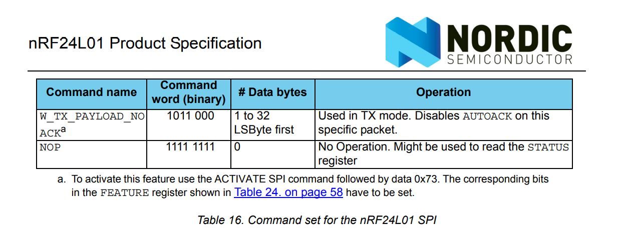
HOWEVER, worthy of note: when you send that address over SPI from an atmega328P to an nRF24L01, the order of the bytes (but not the bits in the bytes) is again reversed. Confused yet? That means the temporal order of the bytes sent over SPI to the nRF24L01P is actually:
0x 80 35 03 58 7B
from left to right. i.e. 0x80 gets sent over SPI first, then 0x35, and so on. "Why is that?" you may ask. It's because, as per the nRF24L01 datasheet, the target address is sent LSByte first over SPI:
Regarding how to configure the S0, LENGTH, and S1 fields on the nRF52, it makes sense to do the following:
S0 = 0
LENGTH = 6
S1=3because then the LENGTH field is properly alligned with the LENGTH bits transmitted by the nRF24L01.
-
To memorialize all that detail in easy to understand c-language code, here is a simple program which converts an nRF52 address into an equivalent nRF24L01P address that you can compile and run on any linux machine using gcc:
#include <stdint.h>
#include <stdio.h>

// This program defines a nRF5x address and converts it into an equivalent nRF24L01P address
// so that a nRF24L01P radio can send packets to the nRF5x device.

// Define prefix and base-address for an nRF5x:
uint8_t this_Node_Nrf5x_Address[] = {0x01, 0xAC, 0xC0, 0x1A, 0xDE};

//Note: Node_Nrf5x_Address[0] is the prefix address, and the remaining bytes are the base-address.

// Define an equivalent address used by an nRF24L01 which, when transmitted, will correspond to the this_Node_Nrf5x_Address
uint8_t nRF24L01P_Tx_Address[5];


// Function that, given a byte, returns a byte with the bits reversed.
// This function is derived from the function originally provided by Nordic Semiconductor (https://github.com/NordicPlayground/nrf51-micro-esb/blob/master/common/micro_esb.c)
uint8_t bytewise_bit_swap(uint32_t inp)
{
    inp = (inp & 0xF0) >> 4 | (inp & 0x0F) << 4;
    inp = (inp & 0xCC) >> 2 | (inp & 0x33) << 2;
    return (inp & 0xAA) >> 1 | (inp & 0x55) << 1;
}


//Convert from the given_Nrf5x_Address to the equivalent nRF24L01P_Tx_Address
void convertAddress() {
  nRF24L01P_Tx_Address[0] = bytewise_bit_swap(this_Node_Nrf5x_Address[4]);
  nRF24L01P_Tx_Address[1] = bytewise_bit_swap(this_Node_Nrf5x_Address[3]);
  nRF24L01P_Tx_Address[2] = bytewise_bit_swap(this_Node_Nrf5x_Address[2]);
  nRF24L01P_Tx_Address[3] = bytewise_bit_swap(this_Node_Nrf5x_Address[1]);
  nRF24L01P_Tx_Address[4] = bytewise_bit_swap(this_Node_Nrf5x_Address[0]);
}

//Given a pointer to an address array of 5 elements, print the address in hexadecimal
void printAddress(uint8_t *theAddress) {
  for (int i=0;i<5;i++) {
    printf("%02X",theAddress[i]);
  }
  printf("\r\n");
}

void main() {
	printf("nRF5x address:  0x");
	printAddress(this_Node_Nrf5x_Address);
	convertAddress();
	printf("equivalent nRF24L01 address:  0x");
        printAddress(nRF24L01P_Tx_Address);
}
In this example, the output is:
nRF5x address:  0x01ACC01ADE
equivalent nRF24L01 address:  0x7B58033580
:grin:
-
That's probably it for this thread. Proof of concept is working, and time to move on. Thank you to the few who had anything to say. Hopefully there will be more of a community again after the chip shortage is over. If not, I hope what has already been posted is at least preserved in some retrievable way so as not to be completely lost in the sands of time.
@NeverDie said in Most reliable "best" radio:
not to be completely lost in the sands of time.
Wish I could do more from my end. As long as this forum and the web exists... your library of knowledge will be of great value to me, and I presume, to others. I thank you!