110v-230v AC to Mysensors PCB board
-
@aproxx Could you clarify the capacitors please? C2 on a post in this thread is 100uF but there are hard to get as ceramics and even the half height ones I have make the arduino stand very high off the board.
Thanks muchly!
@shabba http://nl.aliexpress.com/item/100pcs-lot-Multilayer-ceramic-capacitor-0-1uF-104-50V-100nF-104M/32429917283.html?ws_ab_test=searchweb201556_7_79_78_77_80,searchweb201644_5,searchweb201560_7
you can solder these under the processor board
the 100uF does not have to be a ceramic one...
-
thanks for reply @AWI - The 100nf one does not go under - it is the 100uF one that does. I have a small electrolytic one (it is slightly smaller than the second link you mention) and there is still not enough space - my arduino is too low - I could try and find higher pin stands. I'm sure some ppl will go off and buy all these parts like me so I hope they are aware. Would have been ideal for a SMD really (like the varistor right beside it).
-
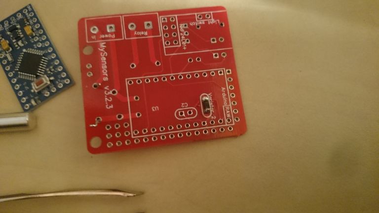
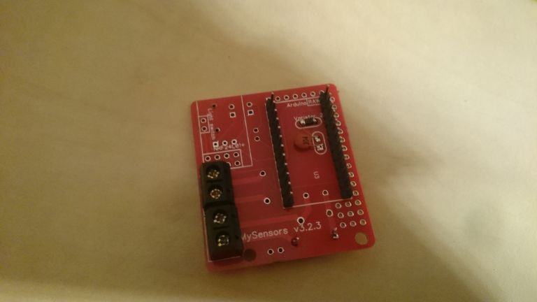
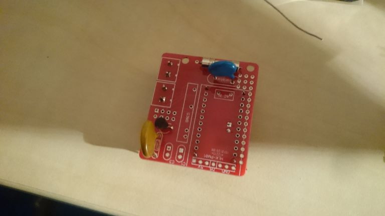
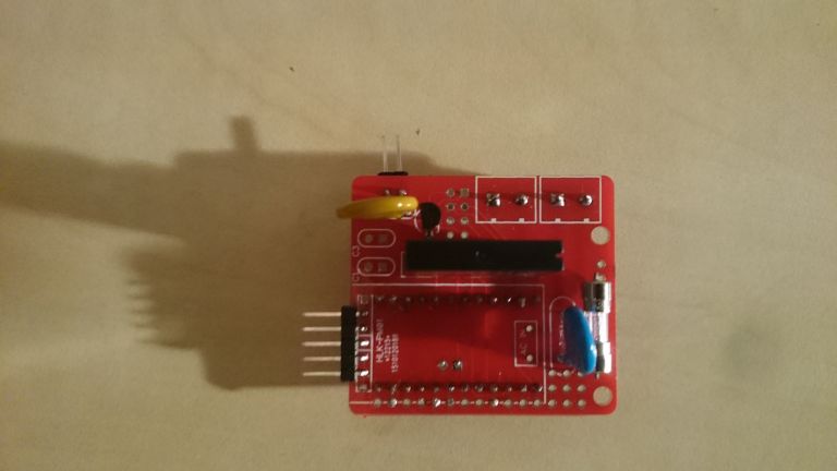
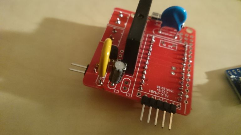
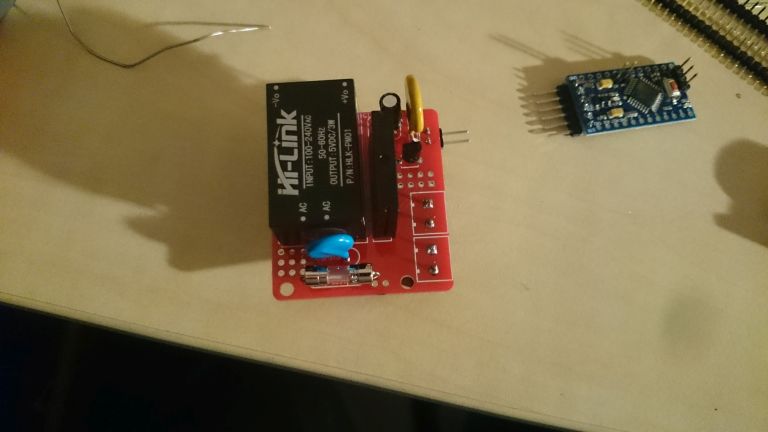
I still have trouble figuring out the C1 and C2. Here are some picture of my build so far.
Not sure all the components are placed correctly.C1 is placed with a small 100nf (104) but BOM in zip say's this is wrong.
As you can see i placed this one, cause the 100uf will not fit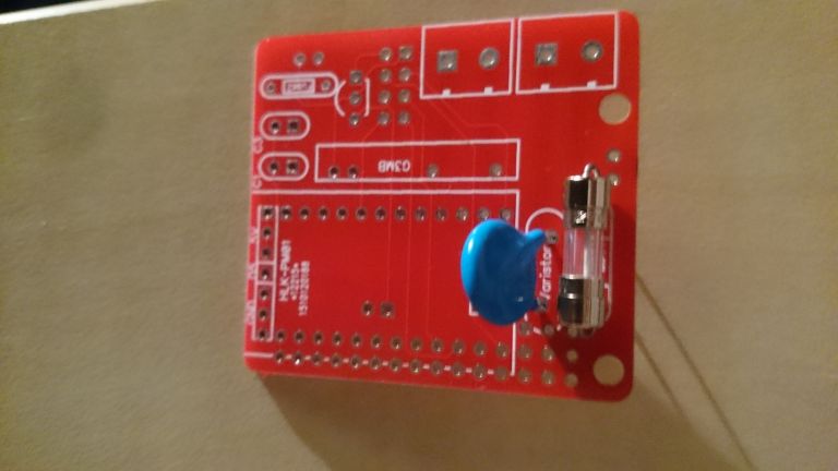
-
I still have trouble figuring out the C1 and C2. Here are some picture of my build so far.
Not sure all the components are placed correctly.C1 is placed with a small 100nf (104) but BOM in zip say's this is wrong.
As you can see i placed this one, cause the 100uf will not fit
-
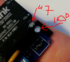
So the regulator needs swapping about and the BOM cap values are incorrect from post (http://forum.mysensors.org/topic/1540/110v-230v-ac-to-mysensors-pcb-board/37) above that states :::
C1 100nF capacitor
C2 100uF capacitor
C3 4.7uF capacitor?
-
Hmmm. I got the 5.5V DC varistor from another AliExpress seller and I'm a bit puzzled as to why it starts smoking after a few seconds. Tried several of them. The HLK gives a solid 5V output. I'm assuming I got some lower voltage varistors by mistake?
-
So the regulator needs swapping about and the BOM cap values are incorrect from post (http://forum.mysensors.org/topic/1540/110v-230v-ac-to-mysensors-pcb-board/37) above that states :::
C1 100nF capacitor
C2 100uF capacitor
C3 4.7uF capacitor?
-
Hmmm. I got the 5.5V DC varistor from another AliExpress seller and I'm a bit puzzled as to why it starts smoking after a few seconds. Tried several of them. The HLK gives a solid 5V output. I'm assuming I got some lower voltage varistors by mistake?
@bjornhallberg Maybe I've missed reading something, but why use a varistor for 5 Vdc and not a zener diode?
-
@shabba Right... if you look at the schematics
you can see that the two capacitors can be swapped without consequences
-
@bjornhallberg Maybe I've missed reading something, but why use a varistor for 5 Vdc and not a zener diode?
@m26872 You're probably right, I just followed the BOM. I'll see if I can stock up on some diodes from AliExpress for future use.
-
Just a stupid question, the "G3MB-202P DC-AC PCB SSR In 5VDC,Out 240V AC 2A " What happens if I forget and plug something more power-hungry like a toaster or a microwave-owen? does any of the fuses blow or does the relay break ?
-
there is no fuse on the relay switch so I guess either the PCB or the relay will fail.
-
I've seen commercial products with a thermal fuse glued to the switching side of the relay. Maybe that would help some in such situation.
-
Whould a 5.1V zener work?
edit: removed the link to the product so that no one would buy it the specs of it is to tight to be used with HLK.
-
@m26872 Indeed, mine is 5.08V (with no load). I ordered some 5.1V and 5.6V 1206 SMD diodes from Ali for future use. Plus some 3.6V. And a set of DIP diodes.
-
@m26872 Indeed, mine is 5.08V (with no load). I ordered some 5.1V and 5.6V 1206 SMD diodes from Ali for future use. Plus some 3.6V. And a set of DIP diodes.
@bjornhallberg said:
I ordered some 5.1V and 5.6V 1206 SMD diodes
Just to remember, the typical zeners are 1W , which gives a max of 200mA of output capacity, pretty enough for Arduino+radio, but maybe not enough for many relays / Leds etc. And if they burn due overload, they will allow all voltage/current flowing from PSU into arduino.
That explains why we suggested the varistor, in order to short the PSU output and trigger its internal protection. Strange that your varistors didn't survive... Bad lot? Maybe they are not 5.5V as stated?
Home Assistant / Vera Plus UI7
ESP8266 GW + mySensors 2.3.2
Alexa / Google Home