110v-230v AC to Mysensors PCB board
-
@Yveaux No, also still waiting for the order to arrive. But a coil resistance of 20-25 Ohm means driving the coil with a FET. Not directly from a atmega328 pin.
@GertSanders said:
@Yveaux No, also still waiting for the order to arrive. But a coil resistance of 20-25 Ohm means driving the coil with a FET. Not directly from a atmega328 pin.
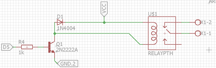
Correct. Here's how I wired the songle relay on my Lithium Ion Sensor PCB:
@GertSanders said:
@Porky6666 : only switches 3A, SONGLE relay can switch 10A.
I wouldn't trust both of them when it comes to switching high amp devices over 3A. I think there is a reason no german electronics shop sells songle relays :smile:
Plus, relays from an electronics shop in your country might cost the same than the songle relays or will just be a tiny bit more expensive.
At least this is true for 5V relays. 3V relays are hard to find (at least in germany)
-
@GertSanders said:
@Yveaux No, also still waiting for the order to arrive. But a coil resistance of 20-25 Ohm means driving the coil with a FET. Not directly from a atmega328 pin.
Correct. Here's how I wired the songle relay on my Lithium Ion Sensor PCB:
@GertSanders said:
@Porky6666 : only switches 3A, SONGLE relay can switch 10A.
I wouldn't trust both of them when it comes to switching high amp devices over 3A. I think there is a reason no german electronics shop sells songle relays :smile:
Plus, relays from an electronics shop in your country might cost the same than the songle relays or will just be a tiny bit more expensive.
At least this is true for 5V relays. 3V relays are hard to find (at least in germany)
@HenryWhite said:
I wouldn't trust both of them when it comes to switching high amp devices over 3A.
I agree, I plan to switch lights, so my preference goes to the 10A model, just to be sure. I have used the SONGLE 5V versions, and none have ever given me reason to doubt their quality. Since I found a 3V3 powersupply I want to try building a full 3V3 board. Should be fun.
-
@HenryWhite why do we need D1 Diode (if i am write) in that circuit? do this circuit will not work without diode?
(sorry dont know much about electronics) -
@HenryWhite why do we need D1 Diode (if i am write) in that circuit? do this circuit will not work without diode?
(sorry dont know much about electronics)@toabhishekverma https://en.m.wikipedia.org/wiki/Flyback_diode
in short: It is needed to protect the NPN transistor from damage.
The circuit will work without diode, But eventually damage the transistor. -
@GertSanders Have you breadboarded your 3.3V design? I'm a bit worried that removing linear converter will impair the performance of the our fussy nRF clones due to less power supply ripple rejection. I think those going for the ESP8266 are better off.
-
Anyone has an idea where to source the 5.5V varistor? I received a bunch from AliExpress following which seem to be broken.
I found this link http://www.farnell.com/datasheets/575651.pdf. However, there seem to be a bunch of 5.5 V varistor. Can anybody help me figuring out the right ones? -
Anyone has an idea where to source the 5.5V varistor? I received a bunch from AliExpress following which seem to be broken.
I found this link http://www.farnell.com/datasheets/575651.pdf. However, there seem to be a bunch of 5.5 V varistor. Can anybody help me figuring out the right ones? -
@GertSanders Have you breadboarded your 3.3V design? I'm a bit worried that removing linear converter will impair the performance of the our fussy nRF clones due to less power supply ripple rejection. I think those going for the ESP8266 are better off.
@m26872 I have not used the 3V3 version of the Hilink converter, it was just shipped today (ordered last week). It will take a few more weeks to reach me. But then I will test it on my ac board. We will see.
23/FEB: Update: the converters are here. I will make a node with this converter version this weekend. -
@icebob said:
@tomkxy I'm using this one: http://hu.farnell.com/multicomp/mcvz1206m050agt/varistor-multilayer-4vac-0402/dp/2462756
Thanks! It's a pity that the chinese "varistors" seem to be jumpers. I even saw in some offers on AliExpress that they are referred to as jumpers.
-
How can I check whether the solid state relay works at all. My assembled board receives messages and sets state properly, I have 5V on the pin, however the relay does not seem to switch. Should I hear it? Any other ideas for "debugging"?
@tomkxy
Measure the resistance over the AC terminals of the SSR. It should be very high when "open" en very low when "closed". SSRs do not make sounds when they switch, so sound will not give a clue if they work. -
Most SSRs cannot be checked this way because they can only switch AC and not DC. See https://en.wikipedia.org/wiki/Zero_cross_circuit
-
@Cliff-Karlsson Be quick :)
I have the same problem - dont know any better sollution atm... solder for 0.5 sec and remove - then you need to let it cool down before adding more solder. -
I read something before about low temp thermal sensors usally being crimped to place. Do you know how this works and if it is usable on the pcb?
Also the last times I tried to assemble the parts on the pcb I noticed that the holes for one of the fuses are too narrow for the standard brown(?) auto reset fuse. I have managed to destroy the solderpads every time I tried to drill the holes a little bigger.
Can I use a standard glass fuse for this one with the same value? -
Just a couple of questions. Most of the components are 240V, are these the same as used for 110/120v in the US? Also one of the varistors is not available, suggested alternative?
Thanks -
Hi,
thanks for your great work..
great to have chosed a pwm output for the relay (ssr can be used as a dimmer)
but is it possible to add a fuse on the ssr output too ?
and a second switchand imho relay's trace is too near a nrf trace..
and return the draw of le33 :psry for my english
thanks -
Hello,
I love your design!
However, I must have missed something. Considering I want to retain the ability to turn the light off with the wall switch, this board does not allow to connect the relay as a 3-way switch.Also, considering it could be mounted inside the wall (and not only in the lamp base) - having 2-3 relays would be very functional! In my house, it is very common that a single wall mount has 3-4 switches that control 3-4 separate lamps. It will probably make the board bigger, more so if we support 3-way switches (see above comment), but it will be very versatile, especially for 4-way switches (see http://forum.mysensors.org/topic/3173/3-4-way-switch-with-a-relay )
-
Hi Sefi Ninio,
There are two ways you can do it, Either change relay to SPDT Relay which is two way relay. this option is not feasible with this pcb. But if you are not using same PCB you can try SPDT relays.Second option which can work with this setup is ,
Your light switch has two pins, connect them with gpio and 3.3 power .
when switch turn on/off gpio pin input goes high(when on) and low (when off).
You have to write a code to monitor this gpio and if its state changes, you have to toggle the relay state.This is my idea, I havent tried it yet. and I am newbie too, Please comment.
I hope I am clear enough
Regards,
Abhishek -
Hi Sefi Ninio,
There are two ways you can do it, Either change relay to SPDT Relay which is two way relay. this option is not feasible with this pcb. But if you are not using same PCB you can try SPDT relays.Second option which can work with this setup is ,
Your light switch has two pins, connect them with gpio and 3.3 power .
when switch turn on/off gpio pin input goes high(when on) and low (when off).
You have to write a code to monitor this gpio and if its state changes, you have to toggle the relay state.This is my idea, I havent tried it yet. and I am newbie too, Please comment.
I hope I am clear enough
Regards,
AbhishekHi, @toabhishekverma
Well, your suggestion might work, I am not sure a switch that is meant to be connected to 220v mains can be connected to the gpio pin.I think, adding an additional relay to the pcb and allowing them both to behave like a 3way switch will allow for maximum flexibility.
- It could control 2 separate lamps
- It could behave like 2 3-way switches
- It could behave like a single 4-way switch
I would have done it myself, but I have no clue 😀