110v-230v AC to Mysensors PCB board
-
I read something before about low temp thermal sensors usally being crimped to place. Do you know how this works and if it is usable on the pcb?
Also the last times I tried to assemble the parts on the pcb I noticed that the holes for one of the fuses are too narrow for the standard brown(?) auto reset fuse. I have managed to destroy the solderpads every time I tried to drill the holes a little bigger.
Can I use a standard glass fuse for this one with the same value? -
Just a couple of questions. Most of the components are 240V, are these the same as used for 110/120v in the US? Also one of the varistors is not available, suggested alternative?
Thanks -
Hi,
thanks for your great work..
great to have chosed a pwm output for the relay (ssr can be used as a dimmer)
but is it possible to add a fuse on the ssr output too ?
and a second switchand imho relay's trace is too near a nrf trace..
and return the draw of le33 :psry for my english
thanks -
Hello,
I love your design!
However, I must have missed something. Considering I want to retain the ability to turn the light off with the wall switch, this board does not allow to connect the relay as a 3-way switch.Also, considering it could be mounted inside the wall (and not only in the lamp base) - having 2-3 relays would be very functional! In my house, it is very common that a single wall mount has 3-4 switches that control 3-4 separate lamps. It will probably make the board bigger, more so if we support 3-way switches (see above comment), but it will be very versatile, especially for 4-way switches (see http://forum.mysensors.org/topic/3173/3-4-way-switch-with-a-relay )
-
Hi Sefi Ninio,
There are two ways you can do it, Either change relay to SPDT Relay which is two way relay. this option is not feasible with this pcb. But if you are not using same PCB you can try SPDT relays.Second option which can work with this setup is ,
Your light switch has two pins, connect them with gpio and 3.3 power .
when switch turn on/off gpio pin input goes high(when on) and low (when off).
You have to write a code to monitor this gpio and if its state changes, you have to toggle the relay state.This is my idea, I havent tried it yet. and I am newbie too, Please comment.
I hope I am clear enough
Regards,
Abhishek -
Hi Sefi Ninio,
There are two ways you can do it, Either change relay to SPDT Relay which is two way relay. this option is not feasible with this pcb. But if you are not using same PCB you can try SPDT relays.Second option which can work with this setup is ,
Your light switch has two pins, connect them with gpio and 3.3 power .
when switch turn on/off gpio pin input goes high(when on) and low (when off).
You have to write a code to monitor this gpio and if its state changes, you have to toggle the relay state.This is my idea, I havent tried it yet. and I am newbie too, Please comment.
I hope I am clear enough
Regards,
AbhishekHi, @toabhishekverma
Well, your suggestion might work, I am not sure a switch that is meant to be connected to 220v mains can be connected to the gpio pin.I think, adding an additional relay to the pcb and allowing them both to behave like a 3way switch will allow for maximum flexibility.
- It could control 2 separate lamps
- It could behave like 2 3-way switches
- It could behave like a single 4-way switch
I would have done it myself, but I have no clue 😀
-
I have several lamps where I have done something similar. The bulbs are wireless wemo-bulbs and I have connected the wires behind the lampswitch so that the bulbs are always powered. The I have placed a battery powered arduino witch is connected to the wall switch pin3-gnd.
Every time I flip the switch the arduino wakes up and the controller sends a toggle command using REST -
I don't know if this has been answered already. But I have some major problems soldering the thermal fuse to the board. It always blows. Any tips ?
@Cliff-Karlsson said:
I don't know if this has been answered already. But I have some major problems soldering the thermal fuse to the board. It always blows. Any tips ?
Raise the temperature of your soldering iron, and you'll be able to do it quicker with less propagating heat. You could also add some extra bend and length to the fuse legs.
-
Hi, @toabhishekverma
Well, your suggestion might work, I am not sure a switch that is meant to be connected to 220v mains can be connected to the gpio pin.I think, adding an additional relay to the pcb and allowing them both to behave like a 3way switch will allow for maximum flexibility.
- It could control 2 separate lamps
- It could behave like 2 3-way switches
- It could behave like a single 4-way switch
I would have done it myself, but I have no clue 😀
@Sefi-Ninio said:
Hi, @toabhishekverma
Well, your suggestion might work, I am not sure a switch that is meant to be connected to 220v mains can be connected to the gpio pin.I think, adding an additional relay to the pcb and allowing them both to behave like a 3way switch will allow for maximum flexibility.
- It could control 2 separate lamps
- It could behave like 2 3-way switches
- It could behave like a single 4-way switch
I would have done it myself, but I have no clue 😀
@aproxx , what do you think about adding another relay (for a total of 2 on board) and making them 3-way?
-
Another question about the thermal fuse. I might be wrong on this, but I guess its purpose is to break the power if the HLK overheats. But If placed in the intended place would not the PCB need to be on fire to have the thermal fuse be warmed up to 73 deg C?
-
Another question about the thermal fuse. I might be wrong on this, but I guess its purpose is to break the power if the HLK overheats. But If placed in the intended place would not the PCB need to be on fire to have the thermal fuse be warmed up to 73 deg C?
@Cliff-Karlsson said:
Another question about the thermal fuse. I might be wrong on this, but I guess its purpose is to break the power if the HLK overheats. But If placed in the intended place would not the PCB need to be on fire to have the thermal fuse be warmed up to 73 deg C?
I guess you're supposed to glue the thermal fuse to the hlk and run wires from this point to the designated footprint of the fuse on the pcb.
-
@Sefi-Ninio said:
Hi, @toabhishekverma
Well, your suggestion might work, I am not sure a switch that is meant to be connected to 220v mains can be connected to the gpio pin.I think, adding an additional relay to the pcb and allowing them both to behave like a 3way switch will allow for maximum flexibility.
- It could control 2 separate lamps
- It could behave like 2 3-way switches
- It could behave like a single 4-way switch
I would have done it myself, but I have no clue 😀
@aproxx , what do you think about adding another relay (for a total of 2 on board) and making them 3-way?
@Sefi-Ninio said:
@Sefi-Ninio said:
Hi, @toabhishekverma
Well, your suggestion might work, I am not sure a switch that is meant to be connected to 220v mains can be connected to the gpio pin.I think, adding an additional relay to the pcb and allowing them both to behave like a 3way switch will allow for maximum flexibility.
- It could control 2 separate lamps
- It could behave like 2 3-way switches
- It could behave like a single 4-way switch
I would have done it myself, but I have no clue 😀
@aproxx , what do you think about adding another relay (for a total of 2 on board) and making them 3-way?
OK Guys,
I've decided to try and use the original V3.2.3 plans and add another relay to them (with your permission, @aproxx).The board will have to be a bit bigger, I will have to make room for another relay along side the existing one, and I will have to also make room for its connectors.
Not a big problem, I think, as it is already very well designed and has a small footprint, but still.I need a bit of help from you guys, though - I am a complete noob when it comes to the wiring and electricity. I can handle the coding, no problem, but the electricity is very new to me.
I am assuming that besides adding the second relay, no other components need to be added - no resistors, capacitors, varistors etc.
Is my assumption correct?Thanks!
-
@Sefi-Ninio said:
@Sefi-Ninio said:
Hi, @toabhishekverma
Well, your suggestion might work, I am not sure a switch that is meant to be connected to 220v mains can be connected to the gpio pin.I think, adding an additional relay to the pcb and allowing them both to behave like a 3way switch will allow for maximum flexibility.
- It could control 2 separate lamps
- It could behave like 2 3-way switches
- It could behave like a single 4-way switch
I would have done it myself, but I have no clue 😀
@aproxx , what do you think about adding another relay (for a total of 2 on board) and making them 3-way?
OK Guys,
I've decided to try and use the original V3.2.3 plans and add another relay to them (with your permission, @aproxx).The board will have to be a bit bigger, I will have to make room for another relay along side the existing one, and I will have to also make room for its connectors.
Not a big problem, I think, as it is already very well designed and has a small footprint, but still.I need a bit of help from you guys, though - I am a complete noob when it comes to the wiring and electricity. I can handle the coding, no problem, but the electricity is very new to me.
I am assuming that besides adding the second relay, no other components need to be added - no resistors, capacitors, varistors etc.
Is my assumption correct?Thanks!
@Sefi-Ninio said:
I am assuming that besides adding the second relay, no other components need to be added - no resistors, capacitors, varistors etc.
Is my assumption correct?Thanks!
You need at least a second transistor.
-
maybe a fuse to protect relay output.. ?
and plz add a second switch, to control an other node or anything.. -
So basically, I should duplicate the current circuit for the new relay...
-
I am facing a little problem with the fuses. I am using these:
5V DC: http://www.ebay.de/itm/321697892220?_trksid=p2057872.m2749.l2649&ssPageName=STRK%3AMEBIDX%3AIT
When I connect the pcb to power the LED on the Arduino flashes and then the 500 mA Fuse in the 5V circuit dies. I am now using the 300 mA resetable Fuse for the 5V part as well, which seems to work without problems. How can it be, that the 500 mA fuse dies and the 300 mA fuse does not?
-
Jan Gatzke; chinese brand electronics... who knows what can happens....
i ordered all stuff needed to make my pcb with maximun 4x4cms to use inside wall switches (like zwave fibaro modules). i will try to reduce that board by not using connectors and solder the cables directly etc..
Something that i don't know is why use a varistor and fuse on secundary??? arduino already have an polyfuse PPTC Resetable fuse, and someting bad that happens with nrf24 will burn the 3.3V regulator.. its that varistor and fuse realy needed?
-
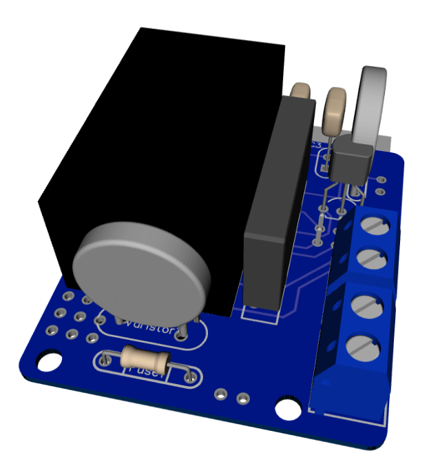
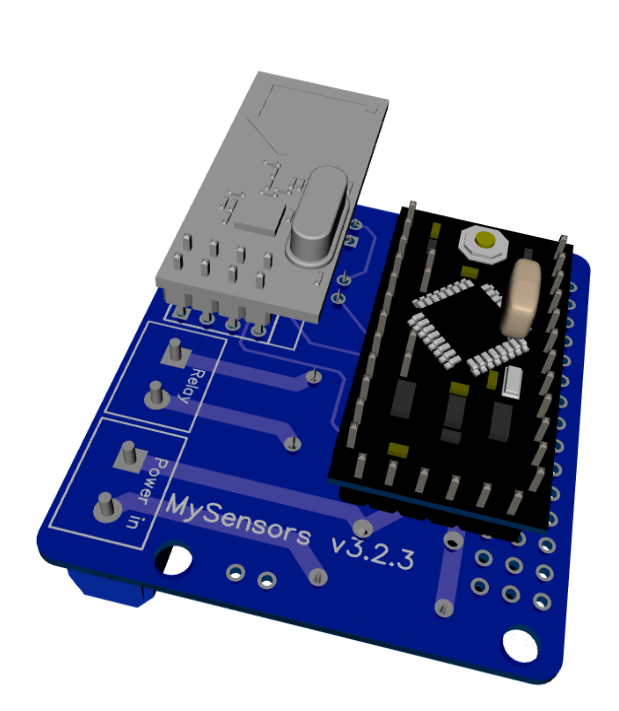
As promised, I've got an update for this project. The board has been tested in the past week, and everything is working as expected. Compared to the previous board I've posted, I have updated the following:
• Solder pads of LE33CZ have been placed a little wider apart to avoid short circuit while soldering.
• Solder pads of the resettable fuse (Fuse2) has been placed closer together to better fit the fuses of the BOM.
• Moved the NRF24L01 connector a bit away from the solid state relay. Should make it easier to solder.
• Moved Fuse2 to another location on the board, away from the 230v circuit.Some 3D pictures (Top and bottom):
Anyone who is interested can order the PCB HERE
Some documentation, and all gerber / DipTrace files (in case you would like to make some modifications) can be found here: MySensors board v3.2.3.zip.
@aproxx hello. can i know how you rendered your PCB layout to 3D , if any tutorial it can guide me
to achieve that .thanks
-
Wow, this thread has been really active in the past few months! I'm sorry for my absence, but I kind of got dragged into other projects.. :)
A new version of the board will be shared soon! Compared to the current board following changes have been made:
- A second solid state relay has been added. This 2nd relay is optional, so if only 1 device needs to be controlled just 1 relay needs to be installed and everything will still work fine.
- The board size has been increased just a little bit to fit this 2nd relay. Size is still 5x5cm only.
- Some components have been moved in order to make it easier to solder them (This was a bit tricky on version 3.2.3 because some components were really close to each other).
- Traces between the relays and the connectors are now 'open air'. So there is no mask on top of the traces. This way it is possible to reinforce the traces. By doing this it shouldn't be any problem to connect a 2A load to the board.
- A temperature cut-off has been added to the board.
- The varistor for the low voltage circuit has been removed because it's not really needed anymore with all the extra security measures on the high voltage side of the board.
Currently this board is still on it's way from China, but as soon as I've received this board I'll share all the documentation and everything else which is needed on this forum! This will probably happen in 3-5 weeks from now, so stay tuned! ;)