Parking Sensor
-
@hek About to make this sensor, very cool! I had already brought a 12v traffic light before I saw this, so now ordered an LED ring, as that makes a lot more sense getting closer to the target area. But could you help out regarding the implementation of the timeout, as I'm pretty terrible at programing :)
-
My rig is disassembled now.
You could add timeout like this (please feedback if it works so I can check it into github):
/** * The MySensors Arduino library handles the wireless radio link and protocol * between your home built sensors/actuators and HA controller of choice. * The sensors forms a self healing radio network with optional repeaters. Each * repeater and gateway builds a routing tables in EEPROM which keeps track of the * network topology allowing messages to be routed to nodes. * * Created by Henrik Ekblad <henrik.ekblad@mysensors.org> * Copyright (C) 2013-2015 Sensnology AB * Full contributor list: https://github.com/mysensors/Arduino/graphs/contributors * * Documentation: http://www.mysensors.org * Support Forum: http://forum.mysensors.org * * This program is free software; you can redistribute it and/or * modify it under the terms of the GNU General Public License * version 2 as published by the Free Software Foundation. * ******************************* * * REVISION HISTORY * Version 1.0 - Created by Henrik Ekblad * * DESCRIPTION * Parking sensor using a neopixel led ring and distance sensor (HC-SR04). * Configure the digital pins used for distance sensor and neopixels below. * NOTE! Remeber to feed leds and distance sensor serparatly from your Arduino. * It will probably not survive feeding more than a couple of LEDs. You * can also adjust intesity below to reduce the power requirements. * * Sends parking status to the controller as a DOOR sensor if SEND_STATUS_TO_CONTROLLER * is defined below. You can also use this _standalone_ without any radio by * removing the SEND_STATUS_TO_CONTROLLER define. */ #define SEND_STATUS_TO_CONTROLLER // Put a comment on this line for standalone mode #include <Adafruit_NeoPixel.h> #include <NewPing.h> #ifdef SEND_STATUS_TO_CONTROLLER #include <SPI.h> #include <MySensor.h> #endif #define NEO_PIN 4 // NeoPixels input pin #define TRIGGER_PIN 6 // Arduino pin tied to trigger pin on the ultrasonic sensor. #define ECHO_PIN 5 // Arduino pin tied to echo pin on the ultrasonic sensor. #define NUMPIXELS 24 // Number of nexpixels in ring/strip #define MAX_INTESITY 20 // Intesity of leds (in percentage). Remeber more intesity requires more power. // The maximum rated measuring range for the HC-SR04 is about 400-500cm. #define MAX_DISTANCE 100 // Max distance we want to start indicating green (in cm) #define PANIC_DISTANCE 5 // Mix distance we red warning indication should be active (in cm) #define PARKED_DISTANCE 20 // Distance when "parked signal" should be sent to controller (in cm) #define PARK_OFF_TIMEOUT 20000 // Number of milliseconds until turning off light when parked. // Note that for older NeoPixel strips you might need to change the third parameter--see the strandtest // example for more information on possible values. Adafruit_NeoPixel pixels = Adafruit_NeoPixel(NUMPIXELS, NEO_PIN, NEO_GRB + NEO_KHZ400); NewPing sonar(TRIGGER_PIN, ECHO_PIN, MAX_DISTANCE); // NewPing setup of pins and maximum distance. #ifdef SEND_STATUS_TO_CONTROLLER #define CHILD_ID 1 MySensor gw; MyMessage msg(CHILD_ID,V_TRIPPED); #endif unsigned long sendInterval = 5000; // Send park status at maximum every 5 second. unsigned long lastSend; int oldParkedStatus=-1; unsigned long blinkInterval = 100; // blink interval (milliseconds) unsigned long lastBlinkPeriod; bool blinkColor = true; // To make a fading motion on the led ring/tape we only move one pixel/distDebounce time unsigned long distDebounce = 30; unsigned long lastDebouncePeriod; int numLightPixels=0; int skipZero=0; void setup() { Serial.begin(115200); Serial.println("Starting distance sensor"); pixels.begin(); // This initializes the NeoPixel library. Serial.println("Neopixels initialized"); #ifdef SEND_STATUS_TO_CONTROLLER gw.begin(); gw.sendSketchInfo("Parking Sensor", "1.0"); gw.present(CHILD_ID, S_DOOR, "Parking Status"); #endif } void loop() { unsigned long now = millis(); int fullDist = sonar.ping_cm(); // Serial.println(fullDist); int displayDist = min(fullDist, MAX_DISTANCE); if (displayDist == 0 && skipZero<10) { // Try to filter zero readings skipZero++; return; } // Check if it is time to alter the leds if (now-lastDebouncePeriod > distDebounce) { lastDebouncePeriod = now; // Update parked status int parked = displayDist != 0 && displayDist<PARKED_DISTANCE; if (parked != oldParkedStatus && now-lastSend > sendInterval) { if (parked) Serial.println("Car Parked"); else Serial.println("Car Gone"); #ifdef SEND_STATUS_TO_CONTROLLER gw.send(msg.set(parked)); #endif oldParkedStatus = parked; lastSend = now; } if (parked && now-lastSend > PARK_OFF_TIMEOUT) { // We've been parked for a while now. Turn off all pixels for(int i=0;i<NUMPIXELS;i++){ pixels.setPixelColor(i, pixels.Color(0,0,0)); } } else { if (displayDist == 0) { // No reading from sensor, assume no object found numLightPixels--; } else { skipZero = 0; int newLightPixels = NUMPIXELS - (NUMPIXELS*(displayDist-PANIC_DISTANCE)/MAX_DISTANCE); if (newLightPixels>numLightPixels) { // Fast raise numLightPixels += max((newLightPixels - numLightPixels) / 2, 1); } else if (newLightPixels<numLightPixels) { // Slow decent numLightPixels--; } } if (numLightPixels>=NUMPIXELS) { // Do some intense red blinking if (now-lastBlinkPeriod > blinkInterval) { blinkColor = !blinkColor; lastBlinkPeriod = now; } for(int i=0;i<numLightPixels;i++){ pixels.setPixelColor(i, pixels.Color(blinkColor?255*MAX_INTESITY/100:0,0,0)); } } else { for(int i=0;i<numLightPixels;i++){ int r = 255 * i/NUMPIXELS; int g = 255 - r; // pixels.Color takes RGB values, from 0,0,0 up to 255,255,255 pixels.setPixelColor(i, pixels.Color(r*MAX_INTESITY/100,g*MAX_INTESITY/100,0)); } // Turn off the rest for(int i=numLightPixels;i<NUMPIXELS;i++){ pixels.setPixelColor(i, pixels.Color(0,0,0)); } } } pixels.show(); // This sends the updated pixel color to the hardware. } } -
My rig is disassembled now.
You could add timeout like this (please feedback if it works so I can check it into github):
/** * The MySensors Arduino library handles the wireless radio link and protocol * between your home built sensors/actuators and HA controller of choice. * The sensors forms a self healing radio network with optional repeaters. Each * repeater and gateway builds a routing tables in EEPROM which keeps track of the * network topology allowing messages to be routed to nodes. * * Created by Henrik Ekblad <henrik.ekblad@mysensors.org> * Copyright (C) 2013-2015 Sensnology AB * Full contributor list: https://github.com/mysensors/Arduino/graphs/contributors * * Documentation: http://www.mysensors.org * Support Forum: http://forum.mysensors.org * * This program is free software; you can redistribute it and/or * modify it under the terms of the GNU General Public License * version 2 as published by the Free Software Foundation. * ******************************* * * REVISION HISTORY * Version 1.0 - Created by Henrik Ekblad * * DESCRIPTION * Parking sensor using a neopixel led ring and distance sensor (HC-SR04). * Configure the digital pins used for distance sensor and neopixels below. * NOTE! Remeber to feed leds and distance sensor serparatly from your Arduino. * It will probably not survive feeding more than a couple of LEDs. You * can also adjust intesity below to reduce the power requirements. * * Sends parking status to the controller as a DOOR sensor if SEND_STATUS_TO_CONTROLLER * is defined below. You can also use this _standalone_ without any radio by * removing the SEND_STATUS_TO_CONTROLLER define. */ #define SEND_STATUS_TO_CONTROLLER // Put a comment on this line for standalone mode #include <Adafruit_NeoPixel.h> #include <NewPing.h> #ifdef SEND_STATUS_TO_CONTROLLER #include <SPI.h> #include <MySensor.h> #endif #define NEO_PIN 4 // NeoPixels input pin #define TRIGGER_PIN 6 // Arduino pin tied to trigger pin on the ultrasonic sensor. #define ECHO_PIN 5 // Arduino pin tied to echo pin on the ultrasonic sensor. #define NUMPIXELS 24 // Number of nexpixels in ring/strip #define MAX_INTESITY 20 // Intesity of leds (in percentage). Remeber more intesity requires more power. // The maximum rated measuring range for the HC-SR04 is about 400-500cm. #define MAX_DISTANCE 100 // Max distance we want to start indicating green (in cm) #define PANIC_DISTANCE 5 // Mix distance we red warning indication should be active (in cm) #define PARKED_DISTANCE 20 // Distance when "parked signal" should be sent to controller (in cm) #define PARK_OFF_TIMEOUT 20000 // Number of milliseconds until turning off light when parked. // Note that for older NeoPixel strips you might need to change the third parameter--see the strandtest // example for more information on possible values. Adafruit_NeoPixel pixels = Adafruit_NeoPixel(NUMPIXELS, NEO_PIN, NEO_GRB + NEO_KHZ400); NewPing sonar(TRIGGER_PIN, ECHO_PIN, MAX_DISTANCE); // NewPing setup of pins and maximum distance. #ifdef SEND_STATUS_TO_CONTROLLER #define CHILD_ID 1 MySensor gw; MyMessage msg(CHILD_ID,V_TRIPPED); #endif unsigned long sendInterval = 5000; // Send park status at maximum every 5 second. unsigned long lastSend; int oldParkedStatus=-1; unsigned long blinkInterval = 100; // blink interval (milliseconds) unsigned long lastBlinkPeriod; bool blinkColor = true; // To make a fading motion on the led ring/tape we only move one pixel/distDebounce time unsigned long distDebounce = 30; unsigned long lastDebouncePeriod; int numLightPixels=0; int skipZero=0; void setup() { Serial.begin(115200); Serial.println("Starting distance sensor"); pixels.begin(); // This initializes the NeoPixel library. Serial.println("Neopixels initialized"); #ifdef SEND_STATUS_TO_CONTROLLER gw.begin(); gw.sendSketchInfo("Parking Sensor", "1.0"); gw.present(CHILD_ID, S_DOOR, "Parking Status"); #endif } void loop() { unsigned long now = millis(); int fullDist = sonar.ping_cm(); // Serial.println(fullDist); int displayDist = min(fullDist, MAX_DISTANCE); if (displayDist == 0 && skipZero<10) { // Try to filter zero readings skipZero++; return; } // Check if it is time to alter the leds if (now-lastDebouncePeriod > distDebounce) { lastDebouncePeriod = now; // Update parked status int parked = displayDist != 0 && displayDist<PARKED_DISTANCE; if (parked != oldParkedStatus && now-lastSend > sendInterval) { if (parked) Serial.println("Car Parked"); else Serial.println("Car Gone"); #ifdef SEND_STATUS_TO_CONTROLLER gw.send(msg.set(parked)); #endif oldParkedStatus = parked; lastSend = now; } if (parked && now-lastSend > PARK_OFF_TIMEOUT) { // We've been parked for a while now. Turn off all pixels for(int i=0;i<NUMPIXELS;i++){ pixels.setPixelColor(i, pixels.Color(0,0,0)); } } else { if (displayDist == 0) { // No reading from sensor, assume no object found numLightPixels--; } else { skipZero = 0; int newLightPixels = NUMPIXELS - (NUMPIXELS*(displayDist-PANIC_DISTANCE)/MAX_DISTANCE); if (newLightPixels>numLightPixels) { // Fast raise numLightPixels += max((newLightPixels - numLightPixels) / 2, 1); } else if (newLightPixels<numLightPixels) { // Slow decent numLightPixels--; } } if (numLightPixels>=NUMPIXELS) { // Do some intense red blinking if (now-lastBlinkPeriod > blinkInterval) { blinkColor = !blinkColor; lastBlinkPeriod = now; } for(int i=0;i<numLightPixels;i++){ pixels.setPixelColor(i, pixels.Color(blinkColor?255*MAX_INTESITY/100:0,0,0)); } } else { for(int i=0;i<numLightPixels;i++){ int r = 255 * i/NUMPIXELS; int g = 255 - r; // pixels.Color takes RGB values, from 0,0,0 up to 255,255,255 pixels.setPixelColor(i, pixels.Color(r*MAX_INTESITY/100,g*MAX_INTESITY/100,0)); } // Turn off the rest for(int i=numLightPixels;i<NUMPIXELS;i++){ pixels.setPixelColor(i, pixels.Color(0,0,0)); } } } pixels.show(); // This sends the updated pixel color to the hardware. } }@hek Received my LED ring in the mail over the weekend. Hooked it up and ran your code. Everything looks to be working great, including the timeout code. Now need to mount and test under real world conditions, i.e,. in the garage with the car. Has anyone done that yet?
-
@hek Received my LED ring in the mail over the weekend. Hooked it up and ran your code. Everything looks to be working great, including the timeout code. Now need to mount and test under real world conditions, i.e,. in the garage with the car. Has anyone done that yet?
-
@hek Received my LED ring in the mail over the weekend. Hooked it up and ran your code. Everything looks to be working great, including the timeout code. Now need to mount and test under real world conditions, i.e,. in the garage with the car. Has anyone done that yet?
@Dan-S. said:
Has anyone done that yet?
Not yet, but I've got plans, big plans :) - I'm working on a leak detector now but when that board is done, I'm going to build an "ultimate garage" PCB that will have the the parking LED, distance sensor, temp/humidity, garage door location sensors, garage door open/close relay, and will automatically close the garage door after a timeout unless a button is pressed.
Here's the way I think about the parking problem: the car moves through 3 different areas: 1) entering garage (not safe), 2) safe to park (far enough in, but not too far), 3) danger - too far. But how do you know what sensor values those correspond to? Especially since mounting the sensor in different areas, at different angles, and with different vehicles will change those values. So if you hold down a button on the sensor, it puts it into config mode. Move the car to the start of the safe area, and push the button to record that sensor reading. Then move the car to the end of the safe parking area and push the button again to record that sensor reading. Then have the software dynamically update the LED ranges to respond to those sensors. Something like: in area 1), illuminate more and more LED's as the car moves through the area. When the car hits area 2), flash the ring green 3 times, then fully illuminate all LED's in green. As the car moves through area 2), decrease the number of LED's illuminated until it hits area 3) where all the LED's flash red.
-
@hek Received my LED ring in the mail over the weekend. Hooked it up and ran your code. Everything looks to be working great, including the timeout code. Now need to mount and test under real world conditions, i.e,. in the garage with the car. Has anyone done that yet?
@Dan-S. Would you mind providing a little detail on your build? I'm totally new and having problems trying to figure out a few things
Do I need a capacitor? If so will 22uf do and where do I hook it up.
I really just looking for a few detailed pics so I can hook things up correctly
Thanks
-
My brother just bought a house and I am going to sucker him into taking up this project by building this for him. I want to add some gas sensors and would like advice on best ones to add. I want to monitor CO, LPG, Butane, and fumes you would get off regular old automotive gas.
-
@Dan-S. Would you mind providing a little detail on your build? I'm totally new and having problems trying to figure out a few things
Do I need a capacitor? If so will 22uf do and where do I hook it up.
I really just looking for a few detailed pics so I can hook things up correctly
Thanks
-
@Dan-S. Would you mind providing a little detail on your build? I'm totally new and having problems trying to figure out a few things
Do I need a capacitor? If so will 22uf do and where do I hook it up.
I really just looking for a few detailed pics so I can hook things up correctly
Thanks
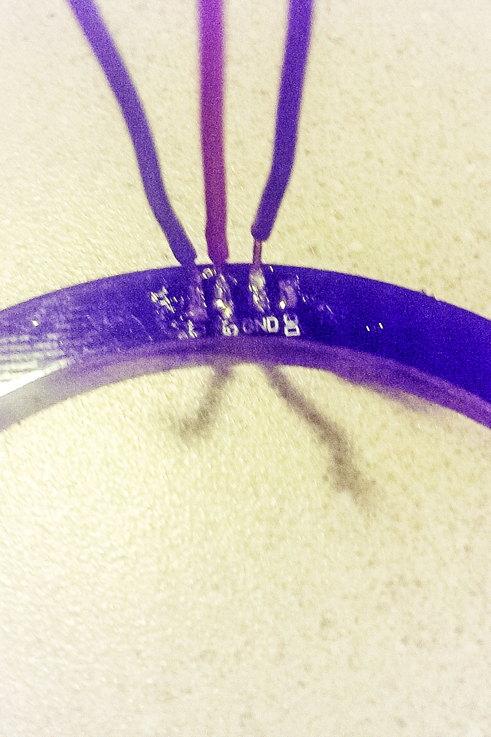
@chilump I am moving from the prototype setup to the garage setup. The first picture shows the LED ring connections. I used solid copper wire because it facilitated what I wanted to do. I squeezed the ends of the wire to flatten them and bent them 90 degrees to make it a bit easier to solder to the solder pads on the led ring. The pads are marked D1,5V,GND and D0. D0 is not used in this application. These are the most difficult connections to make.
 ```
```
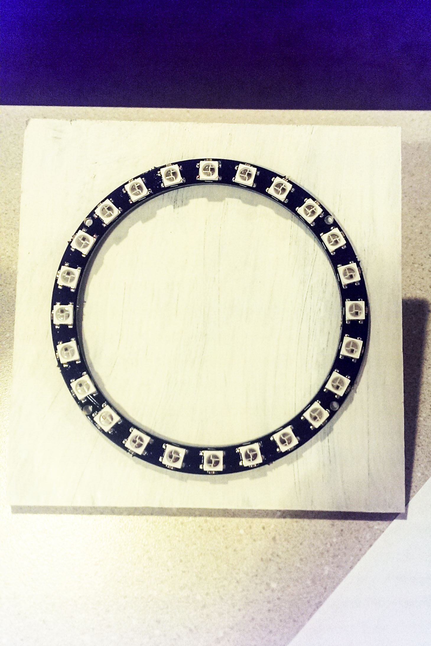
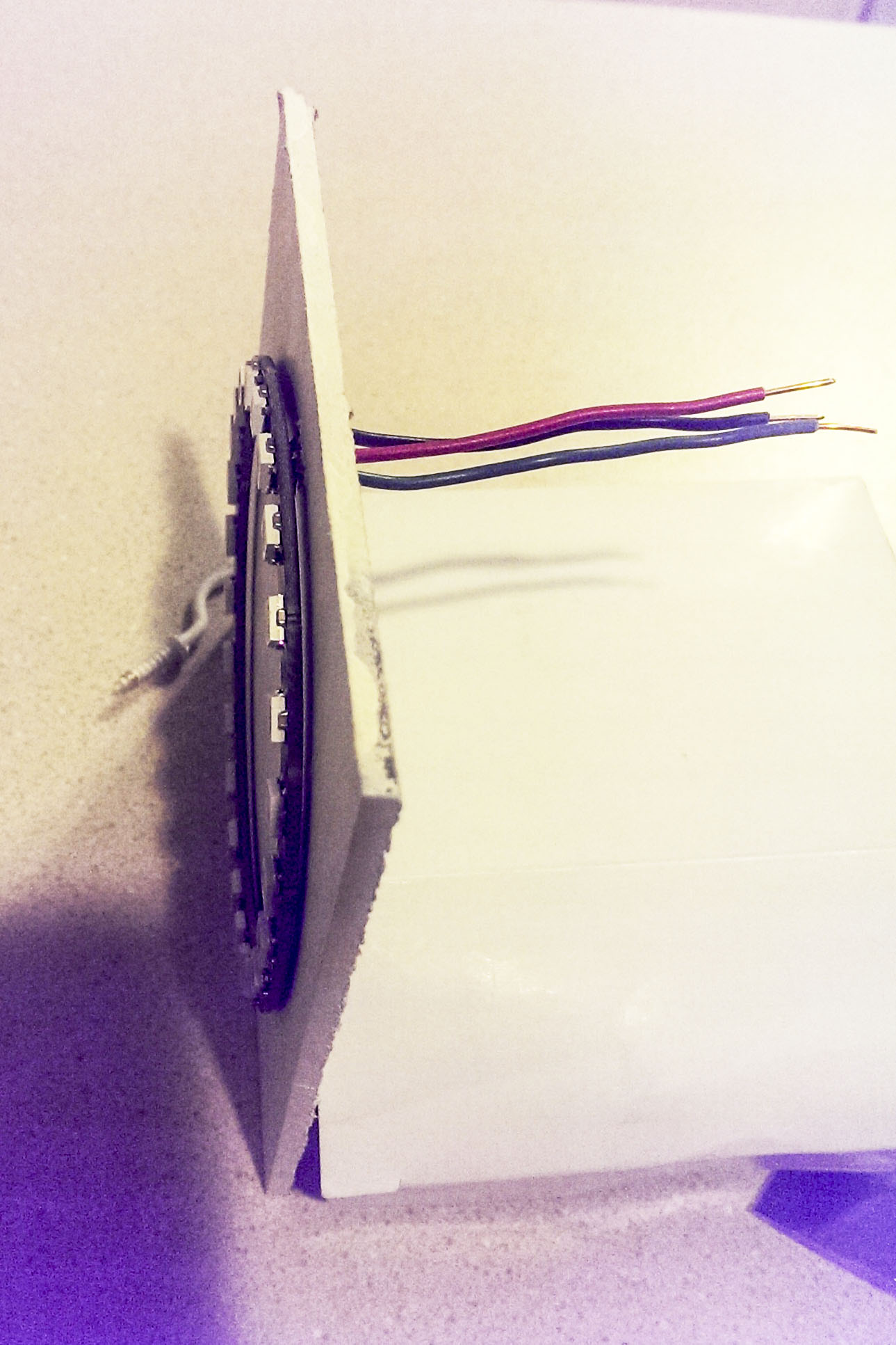
I mounted the ring on a square piece of 1/4 in particle board, drilling holes to feed the wires through. It only has a primer coat on it in the picture.
I will connect a 100uf between the 5v and ground connectors behind the board so it cannot be seen and then mount it on the garage wall.
Hek's 22uf recommendation is probably good enough, but in reading about led ring applications an the internet 100uf was recommended for Adafruit neopixel rings. How much you need is dependent on the led intensity and how rapidly the signal will be changing--for this case 22uf should be ok.I put the distance sensor in one of the standard cases.
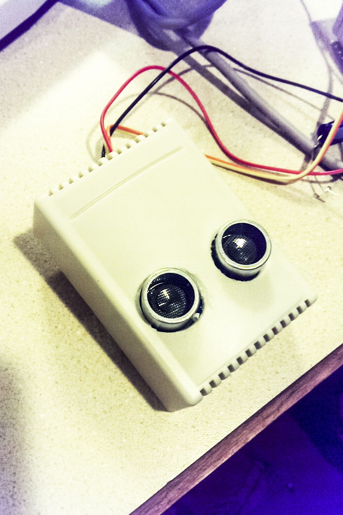
As far as wiring to the Arduino is concerned Hek spells all that out on the mysensor home page if you click on parking sensor. DI of the led ring goes to D4 on Arduino, Trig and echo of the distance sensor got to D6 and D5 of the Arduino respectively. Don't wire the led 5V to the Arduino. It should come directly from the power supply since when the leds are full on they can consume more power than the Arduino can supply. I plugged the Vcc and grnd connections from the distance sensor directly into the Ardouino's pins that were so marked. To be on the safe side I plan on using a 5V 2A DC power supply for this application. All grounds must be common.
-
@chilump I am moving from the prototype setup to the garage setup. The first picture shows the LED ring connections. I used solid copper wire because it facilitated what I wanted to do. I squeezed the ends of the wire to flatten them and bent them 90 degrees to make it a bit easier to solder to the solder pads on the led ring. The pads are marked D1,5V,GND and D0. D0 is not used in this application. These are the most difficult connections to make.
```
I mounted the ring on a square piece of 1/4 in particle board, drilling holes to feed the wires through. It only has a primer coat on it in the picture.
I will connect a 100uf between the 5v and ground connectors behind the board so it cannot be seen and then mount it on the garage wall.
Hek's 22uf recommendation is probably good enough, but in reading about led ring applications an the internet 100uf was recommended for Adafruit neopixel rings. How much you need is dependent on the led intensity and how rapidly the signal will be changing--for this case 22uf should be ok.I put the distance sensor in one of the standard cases.
As far as wiring to the Arduino is concerned Hek spells all that out on the mysensor home page if you click on parking sensor. DI of the led ring goes to D4 on Arduino, Trig and echo of the distance sensor got to D6 and D5 of the Arduino respectively. Don't wire the led 5V to the Arduino. It should come directly from the power supply since when the leds are full on they can consume more power than the Arduino can supply. I plugged the Vcc and grnd connections from the distance sensor directly into the Ardouino's pins that were so marked. To be on the safe side I plan on using a 5V 2A DC power supply for this application. All grounds must be common.
-
@Dan-S. Can a single 5v 2a adapter be used? In that case would everything be wired to the single power adapter?
-
@chilump I hope so since that's exactly how I intend to use it. I will wire the arduino and the led ring directly (and separately ) to the adaptor. I don't want to have to deal with 2 separate power supplies.
-
This is looking great!
But i'm not seeing any "sleeping" is there anyway to have this using the external interrupts on the arduino so it can be running on battery?
( sorry if i'm mistaken, i'm new to arduino :D ) -
@korttoma
Even if it's only active for about 3-4minutes per day?
The problem is i got no way of getting power to where i want to place it.
And also if i did it would have to be something like 230V to usb adapter.
And plugging one of those in outside seems like a fire hazzard (even indoors they are known to start fires).What if i hook it up to a small solar panel to charge the batteries?
Otherwise i guess i'll just have to stick with the old tennisball on a string method :D