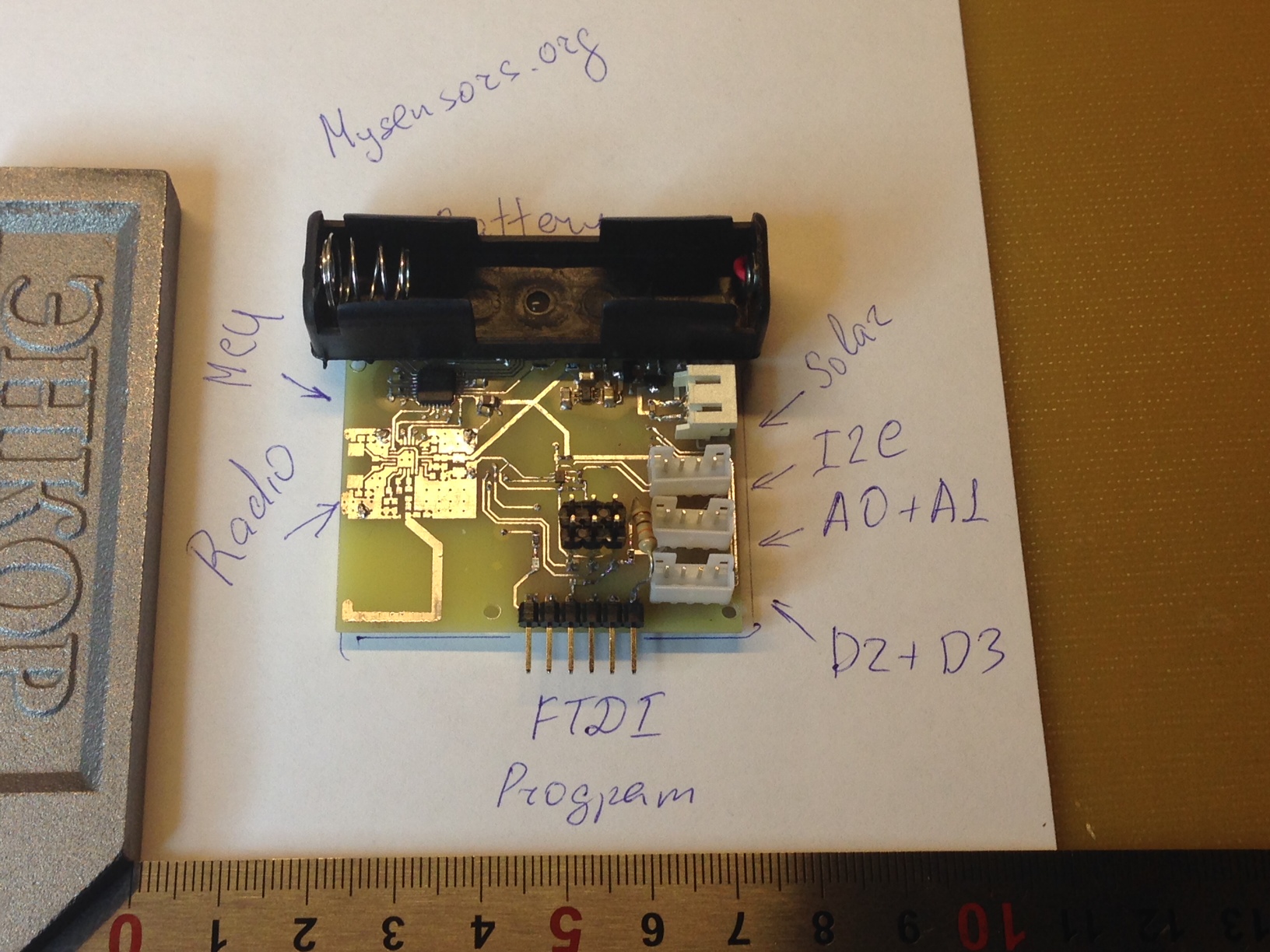
MySensors battey board revision 1.0
-
@axillent said:
There is 0.5mm copper plates, I use office scissors to cut it in a second.
Do you use this thickness for all boards?
And what thickness is the copper? -
Well, needless to say it sounds interesting, when it's been built and tested I'd surely buy a couple of boards. Right now I'm not sure how many actual battery sensors I need and if the sensors I want to run are even viable for battery operation anyway.
I think that for me anyway, more practical things are an issue, like avoiding Swedish customs charges, and finding a GOOD open source automation software so that I can actually use my sensors and not just build them ;-)
If you could also manufacture a separate 3.3V boost circuit based on a modern chip that would be fantastic. I think that is turning out to be a hurdle for most of us that aren't comfortable with SMD/SMT and/or how to nice integrate it into DPI prototyping.
@bjornhallberg I'm an experienced z-wave user and 1/3 devices I currently have managed by my smart-home are battery based
battery based is most easiest way to launch smart-home without big disaster to the home
I also expect an interest to use this battery as outdoor sensors, while z-wave do not have any alternative to this
with double power outdoor sensor can lasts from a single battery for year or even years depending on solar power.for open source software I personally looking forward to have an integration between mysensors and openhub
A separate boost development was finished today and I'm expecting quotes from our partner.
Any preliminary reservations are welcome.
It will be board 15 x 14.8 mm with a switch between 3.3V (up to 100mA) or 5V output (up to 70mA)
it can be sourced by 1-3 cells alkaline or 1-4 cell ni-mh or 1 cell lionHenrik are build already a boards documentations section on the site :)
We expect to have a good documentation to the boards -
@Damme said:
Me myself was thinging on using li-ion and depending on space charge controller but atleast protection.
They come in all sizes and dimensions.lion is too bad for outdoor usage at least for the places in the world were snow is a normal thing at winter))
AAA is much more universal because you can choose between alkilene and rechargeablewith lion you actually fo not need a step-up
you can use 3.3V version of pro-mini with direct connection between VCC and lion
radio you can connect to lion using 3.3V LDO or 1-2 1n4148 connected simultaneously to drop voltage from 4.2 (fresh lion) bellow 3.6V (maximum allowed for radio)@axillent said:
radio you can connect to lion using 3.3V LDO or 1-2 1n4148 connected simultaneously to drop voltage from 4.2 (fresh lion) bellow 3.6V (maximum allowed for radio)
It's probably moot, but the diodes may drop substantially less voltage when the current is very low. Of course, there may be no harm done with such low currents - raising the current brings the Vfwd up too. I'm just noting that the "almost constant Vfwd" only applies to larger currents (eg: 10ma not 10 uA).
-
@axillent Looks good. But is not the LED symbol reversed in the schematics?
I am considering making a board as well for personal use (open HW of course), but using through hole components a bit more extensively for ease of customization. And probably a sockeded MCU so I don't have to include programming interfaces. In the future, I (and hopefully all of you) will push new FW to the board OTA so there will not be a need for holes in the case :)
But I might be interested to join in if your are ordering a batch of these as well. Will it be panelized and pick/placed as well?@Anticimex said:
In the future, I (and hopefully all of you) will push new FW to the board OTA so there will not be a need for holes in the case :)
For that, it's handy to have some extra flash on board. (Ref Moteino and anarduino)
-
@Anticimex said:
In the future, I (and hopefully all of you) will push new FW to the board OTA so there will not be a need for holes in the case :)
For that, it's handy to have some extra flash on board. (Ref Moteino and anarduino)
-
Yep, extra flash for OTA would be nice! Great idea for the next revision.
Would we need extra hardware for this?
If so what is your suggestion?Fulltime Servoy Developer
Parttime Moderator MySensors boardI use Domoticz as controller for Z-Wave and MySensors (previously Indigo and OpenHAB).
I have a FABtotum to print cases. -
@marceltrapman said:
Would we need extra hardware for this?
The flash downloader + flash code could be stored as a bootloader, but that would drop Arduino bootloader compatibility and it will be a challenge to get a stripped MySensors implementation in the bootloader area.
Maybe we can add a small i2c or spi eeprom which is used for temporary storage of the new firmware, but then again, how to get the image data from the eeprom into the ATMega's flash?
-
@ToSa is working on it.
https://github.com/ToSa27/BootloaderReports of successful OTA flash yesterday. But work still remain to make it safer. An extra eeprom would probably help safing things up a bit.
-
@ToSa is working on it.
https://github.com/ToSa27/BootloaderReports of successful OTA flash yesterday. But work still remain to make it safer. An extra eeprom would probably help safing things up a bit.
-
@ToSa is working on it.
https://github.com/ToSa27/BootloaderReports of successful OTA flash yesterday. But work still remain to make it safer. An extra eeprom would probably help safing things up a bit.
@hek said:
Reports of successful OTA flash yesterday.
Nice :)
But work still remain to make it safer. An extra eeprom would probably help safing things up a bit.
I have started my own board design so it would be very interesting for me to know where this is heading at. Any idea what would be preferred to use?
-
In my opinion, keeping Arduino bootloader compatibility (or rather, supporting the Arduino IDE flash protocol) is a must for a OTA bootloader. Even if it would mean some more flash need to be reserved for the bootloader.
But that of course makes it even more interesting to have some external memory support. I2C based EEPROMS have been around for quite some time :) -
I mentioned the Moteino, which has an optional 8 pin 4 Mbit (512KByte) SPI flash chip.
Felix has a modified Uno class bootloader, the Dual Optiboot https://github.com/LowPowerLab/DualOptiboot which takes up 1KByte (vs 512 Bytes for normal OptiBoot).
As I understand it, you send the new code OTA where it's written to the external SPI Flash memory. Then when booting, Dual Optiboot looks for a signature in the Flash memory, and if it found, burns the code into application Flash on the ATMega chip (and it obviously removes that signature). If not signature found in SPI flash, it will boot normally as a normal OptiBoot system.
The Moteino uses the RF12B or RF69 sub-GHz radios. Another cool design. I however like the 2.4GHz nRF24L01+ because it's cheap and very fast, useful in controlling Christmas lights, which take much more bandwidth. I see periodically reporting MySensor style data as another option using the same nRF24L01+ hardware, either instead of the light control function, or in addition to it.
-
OTA is a very promising thing
for the battery board selecting any external chip is also a question of power consumedthe idea with flash is good because it builds the ability of transactional while you able to safely recover from any situation.
but from other hand. you can safely recover even without flash if your second party will take care
look how upload from USB is organized. It do not have a transactional mechanism, it cannot recover by itself
if upload failed the only way to recover is to upload again
why we need OTA to be more safe than regular USB update?but while you a thinking on this i found an issue in the board schematics. I have to add one diod and one 10k resistor to isolate D0 of the MCU from the parasite power coming from the external FTDI programmer. Otherwise the parasite power can destroy nordic chip
-
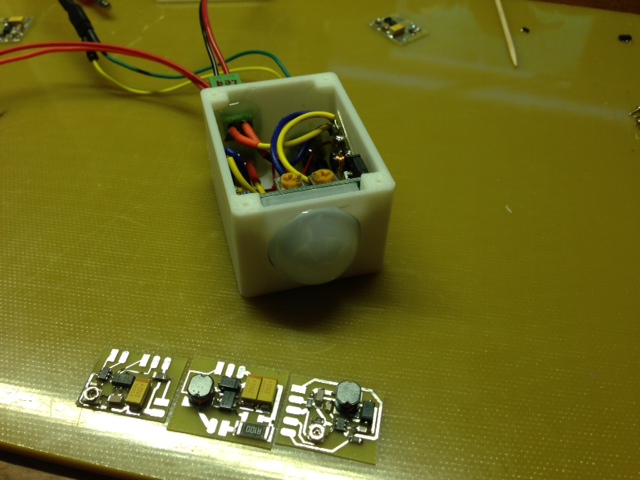
I have news
prototype of the board fully tested except radio
stepup is working fine, power switching is working
programming using external FTDI is working, schematics corrected to get rid from parasite power
al I/O is fine
battery and solar voltage measurement is working
temperature sensor is excellent
it was not simple to solder, the package is unbelievably small - 1.7 x 1.2 mm, 6 pinsnext and last is radio, going to solder it today
-
Interesting that you are choosing GROVE connectors. Are they easy to find (other than SEEEDStudio)?
This makes for an almost drop in alternative to the DevDuino's :http://www.seeedstudio.com/wiki/DevDuino_sensor_node
-
Interesting that you are choosing GROVE connectors. Are they easy to find (other than SEEEDStudio)?
This makes for an almost drop in alternative to the DevDuino's :http://www.seeedstudio.com/wiki/DevDuino_sensor_node
@Zeph said:
Interesting that you are choosing GROVE connectors. Are they easy to find (other than SEEEDStudio)?
GROVE is just a convention on pin assignment. The physical connectors are standard 4 pin 2.0mm pitch (arduino is using 2.54mm)
Two pins are used for GND + VCC and two pins for data/analogue arduino pins
I have them purchased from aliexpressThis makes for an almost drop in alternative to the DevDuino's :http://www.seeedstudio.com/wiki/DevDuino_sensor_node
we are different.we have compact, ready to use double power sensor node
devduino is using an external radio, v1 is using low capacity CR2032, v2 is using two AAA batteries
we are using radio on board, single AAA battery with step up and a solar connector with automatic switchCR2032 is just 80-120mAh
AAA alkiline is about 800-1000mAhtwo batteries on devduino is 1600-2000mAh but it will work until discharge of a cell to 0.9-1.65V (supplying 1.8-3.3 V) depending on the frequency used
we can run until discharge to 0.7V regardless frequency used. Single cell reduces space needed and stepup allows to draws a maximum -
Sorry, I by "almost a drop in replacement" I meant that somebody using a DevDuino could (almost) unplug it, plug in your board, upload the code, and go, if they use the same radio and connectors. (Or vice versa). That flexibility could be good.
I didn't mean that your design was the same or had no advantages! Thanks for listing the key differences, tho.
And - it's "almost" compatible, software wise. I think the data connector has different pin numbers. Not sure about the radio pins (other than dedicated SPI).
But I think that with a change in pin defs, most code could be moved between them, and with the same connectors, a physical switch could be simple.
-
Sorry, I by "almost a drop in replacement" I meant that somebody using a DevDuino could (almost) unplug it, plug in your board, upload the code, and go, if they use the same radio and connectors. (Or vice versa). That flexibility could be good.
I didn't mean that your design was the same or had no advantages! Thanks for listing the key differences, tho.
And - it's "almost" compatible, software wise. I think the data connector has different pin numbers. Not sure about the radio pins (other than dedicated SPI).
But I think that with a change in pin defs, most code could be moved between them, and with the same connectors, a physical switch could be simple.
@Zeph if you have developed a sketch for DevDuino you will just need to change a pin assignment to move it to MySensors board
it is a good practice to use #define for the definition of your hardware pins and move this to abstract level, for example:#define RADIO_CE 8 #define RADIO_CSN 9 #define PIR_SENSOR 3to change this assignment you just need to change this few lines
-
Yes, that's about what I thought. Thanks.
Looking forward to your board being available. I had ordered a couple DevDuinos, but now I'm holding off on ordering more since seeing yours - and for me the option of being able to swap out which is used could be handy.
Looking forward to hearing more about availability and final pricing, when you have it.
Oh, did you use the same temp sensor?