My Ideal sensor node PCB
-
Gentlemen,
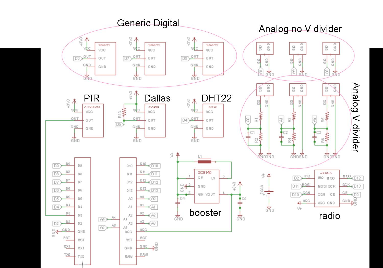
For anyone who is interested I have attached a schematic of my proposed "shield". Have a look if you so choose, and if you notice something wrong or incorrect, please let me know. One thing I'm not sure is...does the DHT22 temperature/humidity sensor need an external pull-up resistor?
@therik said:
Very nice. No "mistakes", just some questions.
For anyone who is interested I have attached a schematic of my proposed "shield". Have a look if you so choose, and if you notice something wrong or incorrect, please let me know.
This is a base board for the Arduino Pro Mini, right? Are you making use of A6 and A7?
Why three voltage dividers of this style? Do you anticipate having multiple higher voltages to measure? I would tend to use one for VRAW. I guess you could populate one half with a resistor and jumper the other, then tie something like an LDR between the analog input and VCC or Ground.
I'm a little unusual, as I want the option to tie the nRF's IRQ to D8 (input capture 1). This is to allow T1 to be used as a high precision timer and capture the time a packet arrives, and I can also use that capture to generate an interrupt based on that - keeping D2 free for INT0.
I am also using an interrupt driven DHTxx lib, which uses Int0 or Int1 (pin 2 or 3) rather than pin 5.
Are the PIR and Dallas (one wire) and DHT22 dedicated footprints on the board, or connectors?
-
Indeed, a pro-mini clone. I thought that A6 and A7 might be too much to squeeze in. I'm thinking of a 3x5 cm board.
Yea, for the voltage dividers, one for measuring the battery level. And two for something else, possibly an IR-based reflective optical sensor. And anything that has a higher output voltage.
Hmm...haven't heard of using nRF's IRQ to D8, can you still wake a sleeping node with this configuration? I guess I just don't have a full grasp on the concept. I just a beginner, so the more I learn the more dangerous I get!
Right, the main sensor on this board is the PIR; which is why I want an interrupt pin to that sensor. However I'd like to also use the magnetic-based sensors also as the main sensor and interrupt.
The PIR, Dallas, DHT22 are separate from the other 'future-proof' region, this should become clear once the layout is complete.
Anyone have a solid answer on whether the DHT22 needs an external pull-up resistor?
@therik said:
Indeed, a pro-mini clone. I thought that A6 and A7 might be too much to squeeze in. I'm thinking of a 3x5 cm board.
OK. I like to use one of them for a dedicated measurement of VRAW, since it cannot be used as an additional digital I/O like A0..A5
Yea, for the voltage dividers, one for measuring the battery level. And two for something else, possibly an IR-based reflective optical sensor. And anything that has a higher output voltage.
What IR based sensor are you considering that returns analog above VCC? Are you thinking of having 5V power supply and sensors with 3.3v APM?
Hmm...haven't heard of using nRF's IRQ to D8, can you still wake a sleeping node with this configuration?
I believe the answer is "yes, but not in the lowest possible power-down mode".
Case 1: The nRF is power up and may generate an interrupt. In that case you are using a significant amount of power; you can save battery by nevertheless mostly powering down at ATMega, but keeping timer 1 active so D8 can generate a Input Capture 1 interrupt won't be a big deal.
Case 2: You want really minimal power - so the nRF is powered down and isn't generating interrrupts. In that case you don't need D2 or D8, and you can go to the lowest power level (including powering off timer 1); the watchdog may be all you leave running (or some other super low power external device).
At least that's my understanding. I'm still learning too.Anyone have a solid answer on whether the DHT22 needs an external pull-up resistor?
I do not use any pull up resister and I've never seen a circuit which used it.
-
My overall thinking is that the breadboard area will allow reasonably simple addition of many types of sensors or actuators, so I am suggesting minimizing the dedicated circuitry and maximizing the breadboard area. However it makes sense to have dedicated space on the PCB for sensors and devices which are likely to be commonly used and especially if they do not fit the 0.1" hole grid. For example, a surface mount LDO regulator for the radio.
There's another candidate which meets this criterion for me, and I've edited it into the Origional Post - onboard external serial Flash. This could be as easy as a SOIC-8 outline (and traces) for the AT24C series, or other serial Flash memory. Optional of course.
@Zeph said:
There's another candidate which meets this criterion for me, and I've edited it into the Origional Post - onboard external serial Flash.
Have a look at this little fella: http://www.digikey.com/product-search/en?mpart=W25X40CLSNIG&vendor=256
Isn't anybody willing to create a SOIC-8 home for this cute little chip (with SPI traces of course to keep it happy)?
512 KBytes of happiness for logging and OTA programming. Unique ID.
Or you can get twice that memory for 2 cents more.(The above is the chip used by the Moteino. The Anarduino uses a heftier 16 MByte chip: http://www.mouser.com/ProductDetail/Spansion/S25FL127SABMFI101/?qs=sGAEpiMZZMtI%252bQ06EiAoG5SEO4xJJ6RlEmMSz7h3HuQ%3D but that too is possible with the same SOIC-8 footprint, I think)
(The Moteino and Anarduino use different and incompatible radios compared to MySensors, but nevertheless contain possible inspirations for our corner of this exciting little world).
-
Just for completeness, my PCBs came in and I've had a chance to solder them up. The PCBs are really nice. iTead have done a great job. @Zeph, turns out that I didn't need to cut my PCBs because the friendly folk at iTead cut them for me.
Here's a photo of a few things soldered on:
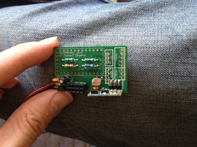
Underneath the APM I have a 1M and 470K resistors for the battery voltage check. There's also a 4.7K resistor for the Dallas DS18B20 temp sensor. Finally there's a 4.7K resistor for the LDR divider circuit.
You can also see the 4x2 header for the radio, the LDR itself, and the 3.3v step-up converter.
Here's the (almost) finished package:
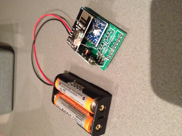
You can see all the exposed solder pads for my various sensor configurations (motion, humidity, baro pressure, door reed switch, distance and soil moisture).
The range on the nRF24 is fine. I put my gateway at one end of the apartment and it easily picked up my sensor at the other end of the apartment (about 10m away through two thick internal walls). So I'm not worried about the nRF24 being parallel to the GND plane.
I actually took off the 4.7uF cap. It's probably my PCB (don't think the auto-route did a great job of it) but it made the radio flaky. Works just fine without it.
Now to find a box to put it in...
-
Just for completeness, my PCBs came in and I've had a chance to solder them up. The PCBs are really nice. iTead have done a great job. @Zeph, turns out that I didn't need to cut my PCBs because the friendly folk at iTead cut them for me.
Here's a photo of a few things soldered on:
Underneath the APM I have a 1M and 470K resistors for the battery voltage check. There's also a 4.7K resistor for the Dallas DS18B20 temp sensor. Finally there's a 4.7K resistor for the LDR divider circuit.
You can also see the 4x2 header for the radio, the LDR itself, and the 3.3v step-up converter.
Here's the (almost) finished package:
You can see all the exposed solder pads for my various sensor configurations (motion, humidity, baro pressure, door reed switch, distance and soil moisture).
The range on the nRF24 is fine. I put my gateway at one end of the apartment and it easily picked up my sensor at the other end of the apartment (about 10m away through two thick internal walls). So I'm not worried about the nRF24 being parallel to the GND plane.
I actually took off the 4.7uF cap. It's probably my PCB (don't think the auto-route did a great job of it) but it made the radio flaky. Works just fine without it.
Now to find a box to put it in...
-
@Zeph said:
There's another candidate which meets this criterion for me, and I've edited it into the Origional Post - onboard external serial Flash.
Have a look at this little fella: http://www.digikey.com/product-search/en?mpart=W25X40CLSNIG&vendor=256
Isn't anybody willing to create a SOIC-8 home for this cute little chip (with SPI traces of course to keep it happy)?
512 KBytes of happiness for logging and OTA programming. Unique ID.
Or you can get twice that memory for 2 cents more.(The above is the chip used by the Moteino. The Anarduino uses a heftier 16 MByte chip: http://www.mouser.com/ProductDetail/Spansion/S25FL127SABMFI101/?qs=sGAEpiMZZMtI%252bQ06EiAoG5SEO4xJJ6RlEmMSz7h3HuQ%3D but that too is possible with the same SOIC-8 footprint, I think)
(The Moteino and Anarduino use different and incompatible radios compared to MySensors, but nevertheless contain possible inspirations for our corner of this exciting little world).
@Zeph said:
Have a look at this little fella: http://www.digikey.com/product-search/en?mpart=W25X40CLSNIG&vendor=256
Interesting but even when I am willing to stock them up (50 pcs) the shipment costs exceed the price of them :(
Fulltime Servoy Developer
Parttime Moderator MySensors boardI use Domoticz as controller for Z-Wave and MySensors (previously Indigo and OpenHAB).
I have a FABtotum to print cases. -
@Zeph said:
Have a look at this little fella: http://www.digikey.com/product-search/en?mpart=W25X40CLSNIG&vendor=256
Interesting but even when I am willing to stock them up (50 pcs) the shipment costs exceed the price of them :(
@marceltrapman Have you looked at AliExpress? Seems they had a few sellers offering this chip.
-
@marceltrapman Have you looked at AliExpress? Seems they had a few sellers offering this chip.
@bjornhallberg said:
@marceltrapman Have you looked at AliExpress? Seems they had a few sellers offering this chip.
I never considered them. Took the plunge for a little less then 0,19 EU per piece :)
-
@Zeph said:
Have a look at this little fella: http://www.digikey.com/product-search/en?mpart=W25X40CLSNIG&vendor=256
Interesting but even when I am willing to stock them up (50 pcs) the shipment costs exceed the price of them :(
@marceltrapman said:
@Zeph said:
Have a look at this little fella: http://www.digikey.com/product-search/en?mpart=W25X40CLSNIG&vendor=256
Interesting but even when I am willing to stock them up (50 pcs) the shipment costs exceed the price of them :(
Sorry. The problem with 4 Mb chip is that it's so cheap one feels bad about the shipping cost! :-)
I was also looking at some 128Mb (16 MB) flash memories at $2.78, where the shipping would be a smaller part of the order
More seriously, I hope the Ali Express order works well.
-
Just for completeness, my PCBs came in and I've had a chance to solder them up. The PCBs are really nice. iTead have done a great job. @Zeph, turns out that I didn't need to cut my PCBs because the friendly folk at iTead cut them for me.
Here's a photo of a few things soldered on:
Underneath the APM I have a 1M and 470K resistors for the battery voltage check. There's also a 4.7K resistor for the Dallas DS18B20 temp sensor. Finally there's a 4.7K resistor for the LDR divider circuit.
You can also see the 4x2 header for the radio, the LDR itself, and the 3.3v step-up converter.
Here's the (almost) finished package:
You can see all the exposed solder pads for my various sensor configurations (motion, humidity, baro pressure, door reed switch, distance and soil moisture).
The range on the nRF24 is fine. I put my gateway at one end of the apartment and it easily picked up my sensor at the other end of the apartment (about 10m away through two thick internal walls). So I'm not worried about the nRF24 being parallel to the GND plane.
I actually took off the 4.7uF cap. It's probably my PCB (don't think the auto-route did a great job of it) but it made the radio flaky. Works just fine without it.
Now to find a box to put it in...
-
@ServiceXp
Thanks mate! I've soldered up 3 of the boards now and they're all working fine.So far I've made one just with temp and light. One with temp, light and humidity, and one with temp, light, humidity and pressure. I'll make one more tonight that will just have temp and soil moisture.
I'm not entirely happy with the two caps at the bottom of the board. The auto-route feature of Eagle is good, but I don't think it quite got that right. Seems to run fine without the two caps so the PCBs are not a write-off.
I've got way more boards than I need. So I'm happy to send 3 off to you. PM me your address.
@Bandra said:
I'm not entirely happy with the two caps at the bottom of the board.
What is it that you are not happy about?
Trying to learn here because I am still not sure if I will just make my boards myself or keep it with one or two prototypes and use iTead as well...
Talking about iTead, I saw that they can also check your board, did you decide against that?
-
@ServiceXp
Thanks mate! I've soldered up 3 of the boards now and they're all working fine.So far I've made one just with temp and light. One with temp, light and humidity, and one with temp, light, humidity and pressure. I'll make one more tonight that will just have temp and soil moisture.
I'm not entirely happy with the two caps at the bottom of the board. The auto-route feature of Eagle is good, but I don't think it quite got that right. Seems to run fine without the two caps so the PCBs are not a write-off.
I've got way more boards than I need. So I'm happy to send 3 off to you. PM me your address.
-
@Bandra said:
I'm not entirely happy with the two caps at the bottom of the board.
What is it that you are not happy about?
Trying to learn here because I am still not sure if I will just make my boards myself or keep it with one or two prototypes and use iTead as well...
Talking about iTead, I saw that they can also check your board, did you decide against that?
@marceltrapman
The auto-route feature in Eagle attempts to make the most efficient board layout it can. To do that, it seems to join the traces where ever it can. When you click on the rats nest button, it will combine any GND traces that it can. Since the cap sits on GND, for example, it assumes it can put it anywhere on a GND trace, and physically dislocates it from the radio pins. I just noticed that on my board, for example, the nRF24 cap doesn't sit directly across + and -.So my next go I would manually route those traces first then auto-route the rest.
It's no big deal, because if I get bad reception then I can always solder the decoupling cap directly onto the radio.
I did choose the option to check my board. It's my very first PCB (which is why I didn't pick up the problem) so I was expecting for them to find lots of problems. But it turns out that technically my board is correct. It's the "logic" of the board that's wrong, so iTead could not have picked this up.
Lesson learned!
-
Is anyone with a tested and working sensors PCB willing to share the design files ? This way people can order directly from oshpark, iteed etc. I'm sure these will make a great addition to the mysensors.org website.
-
-
@Zeph said:
There's another candidate which meets this criterion for me, and I've edited it into the Origional Post - onboard external serial Flash.
Have a look at this little fella: http://www.digikey.com/product-search/en?mpart=W25X40CLSNIG&vendor=256
Isn't anybody willing to create a SOIC-8 home for this cute little chip (with SPI traces of course to keep it happy)?
512 KBytes of happiness for logging and OTA programming. Unique ID.
Or you can get twice that memory for 2 cents more.(The above is the chip used by the Moteino. The Anarduino uses a heftier 16 MByte chip: http://www.mouser.com/ProductDetail/Spansion/S25FL127SABMFI101/?qs=sGAEpiMZZMtI%252bQ06EiAoG5SEO4xJJ6RlEmMSz7h3HuQ%3D but that too is possible with the same SOIC-8 footprint, I think)
(The Moteino and Anarduino use different and incompatible radios compared to MySensors, but nevertheless contain possible inspirations for our corner of this exciting little world).
@Zeph said:
Have a look at this little fella: http://www.digikey.com/product-search/en?mpart=W25X40CLSNIG&vendor=256
Any proposals for DIP-8 flash to use for breadboard testing that are compatible to avoid surprises when switching to the SOT-8 ones later-on? Do all of these SPIflash chips use the same "protocol"?
-
Here's a dip version of the next larger brother from adafruit:for $1.95 https://www.adafruit.com/products/1564
Then digikey has the soic for $0.43
http://www.digikey.com/product-search/en?x=0&y=0&lang=en&site=us&keywords=W25Q80BV(Digikey has listings for the dip version but 0 stock)
I have not used these so I don't have any first hand recommendation. I cued in on this line because Felix uses the 4Mbit version on the Moteino, so I looked it up and thought it looked good.
(The Anarduino uses a 128 Mbit spi flash chip from a different line).