In wall - PCB, (AC to DC 5v)
-
Nice! Good images, and thanks for the scale. Is your wall box also 4 cm deep, like the ones I have in my house?
-
Hi all,
It looks very good @sundberg84, It's still a little bit bigger than fibaro switch but costs much much less :) Looking forward to see your next revisionIs it any chance to place another screw terminal to allow turn on/off not only via radio but with the local button as well?
From other side as a workaround it still should be possible to hard soldering some wires to appropriate pin on arduino side.I'm wondering why some Asia manufacturer is not able to build a tiny pcb with integrated arduino, nrf radio, ac-dc trafo and relay on one single board to keep small footprint.
-
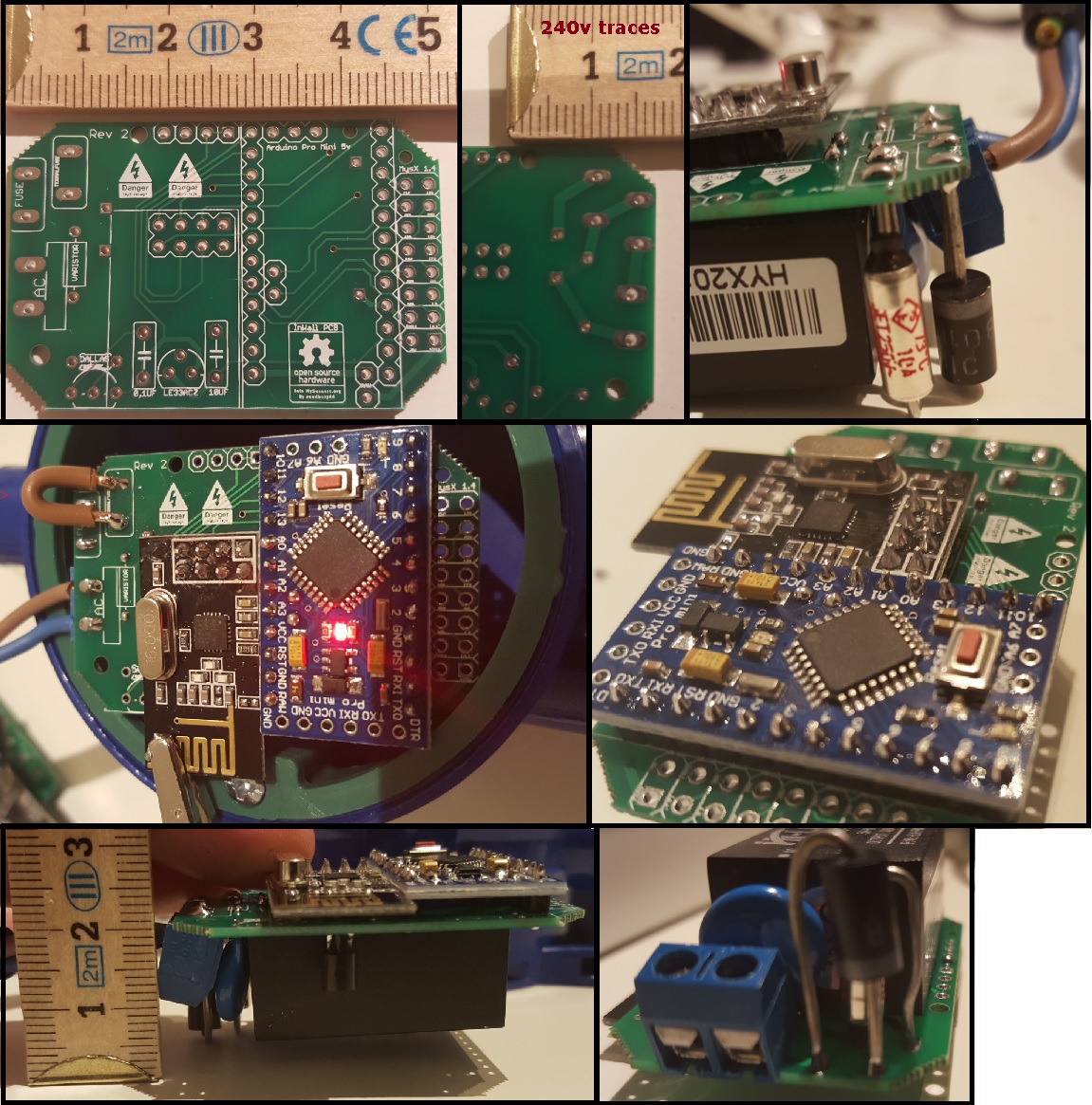
I recieved my PCB today - Yea!
The good news is - its working, and it fits inside my wall socket.
The bad news is that as always i will need another revision - the hole for the fuses are to close to each other.Some pictures:
Anyone with any input on this?
@sundberg84 Good job and nice fit! Looks like you can even make the discussed separate box-in-box for it if you like.
Do you have a BOM of the parts you used this far? And which ones you need to replace or move around. -
@samuel235 - No components between the NRF and the PCB but yes, if you mean on the other side of the pcb. There is the 5->3.3v converter and caps.
@martinhjelmare - Yes, 4.5cm it seems but there is some room on the sides so i hope to be able to squise in a relay.
@łukasz-rybak - You can connect a local button between d3 and gnd on the MYSX connector on the right side. This can read the switch and change a relay depending on what state the switch is in.
@m26872 - Yea, lets hope so... ill do another revision of the board and lets see where this ends up.
-
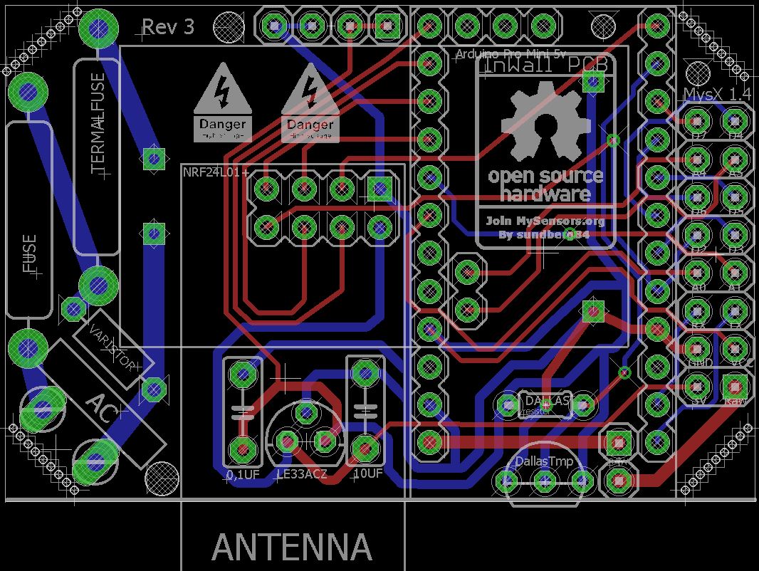
So, my rev 3 is coming along:
- moved the Dallas temp sensor
- added some more space for the 240v fuses:
- labels changed
The BOM? Is that the parts used?
I have used what we concluded here:
http://forum.mysensors.org/topic/1607/safe-in-wall-ac-to-dc-transformersThis is what i bought (no garantees given this works/doesnt burn)
HKL-PM01 http://www.ebay.com/sch/sis.html?_nkw=HLK-PM01+AC-DC+220V+to+5V+Step-Down+Power+Supply+Module+Household+Switch+Q15274&_id=351418782712&&_trksid=p2057872.m2749.l2658
(DO NOT BUY THIS!!)Fuse http://www.ebay.com/itm/111433875797?_trksid=p2057872.m2749.l2649&ssPageName=STRK%3AMEBIDX%3AIT
Thermal Fuse http://www.ebay.com/itm/221560426284?_trksid=p2057872.m2749.l2649&ssPageName=STRK%3AMEBIDX%3AIT
Varistor http://www.ebay.com/itm/260848704608?_trksid=p2057872.m2749.l2649&ssPageName=STRK%3AMEBIDX%3AITPro Mini 5v
Nrf radio
LE33a http://www.ebay.com/itm/400691492273?_trksid=p2057872.m2749.l2649&ssPageName=STRK%3AMEBIDX%3AIT -
@samuel235 - No components between the NRF and the PCB but yes, if you mean on the other side of the pcb. There is the 5->3.3v converter and caps.
@martinhjelmare - Yes, 4.5cm it seems but there is some room on the sides so i hope to be able to squise in a relay.
@łukasz-rybak - You can connect a local button between d3 and gnd on the MYSX connector on the right side. This can read the switch and change a relay depending on what state the switch is in.
@m26872 - Yea, lets hope so... ill do another revision of the board and lets see where this ends up.
@sundberg84 said:
@samuel235 - No components between the NRF and the PCB but yes, if you mean on the other side of the pcb. There is the 5->3.3v converter and caps.
Just to let you know, I meant in between the nRF board and the PCB, so thank you for letting me know :)
Rev 3 is looking pretty neat and tidy if i must say so. Keep up the awesome design work, I'm learning off of you, thank you! ;)
-
@sundberg84 Yes, the BOM is the list of all components that populates your PCB. References, values, source and all other specifications that the "manufacturer" will need.
I was actually mostly interested in the fuse looking like a big diode in your picture. Is it ordered from that link you showed? Which value is it?
-
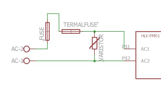
@m26872 Its the slow blow fuse, and I ordered 240v, dont remember which current and that is offcourse whats interesting. On a business trip but can check this weekend when i get home. The datasheet for the HLK refers to:
Maximum input current ≤0.2 A
Input current surge ; ≤10 AController: Proxmox VM - Home Assistant
MySensors GW: Arduino Uno - W5100 Ethernet, Gw Shield Nrf24l01+ 2,4Ghz
MySensors GW: Arduino Uno - Gw Shield RFM69, 433mhz
RFLink GW - Arduino Mega + RFLink Shield, 433mhz -
@m26872 Its the slow blow fuse, and I ordered 240v, dont remember which current and that is offcourse whats interesting. On a business trip but can check this weekend when i get home. The datasheet for the HLK refers to:
Maximum input current ≤0.2 A
Input current surge ; ≤10 A@sundberg84 Could I ask where you order your boards from, which manufacturer do you use and would you recommend them?
-
I order from itead. Works great and good quality.
-
@m26872 Its the slow blow fuse, and I ordered 240v, dont remember which current and that is offcourse whats interesting. On a business trip but can check this weekend when i get home. The datasheet for the HLK refers to:
Maximum input current ≤0.2 A
Input current surge ; ≤10 A@sundberg84 The closest fuse-alike I've found in a DO-204 (semiconductor-) package, is the TVS diode. Typical breakdown voltage seems to usually be a lot lower than 230V, so I guess you should apply a low voltage (<10V) if you want to test if it conducts. Fuse break current is the most interesting test of course.
-
I order from itead. Works great and good quality.
@sundberg84 They look like they provide a pretty stable and awesome service. What sort of turn around did you get from ordering to receiving the PCB?
-
@mzuidwijk : The HLK library for eagles: HKLPM01.rar
@m26872 : Since the ciriut works it conducts, i have not tested at which point it breaks because i dont have that equipment :( would be great if we somehow could estabilsh the right compont to use.Controller: Proxmox VM - Home Assistant
MySensors GW: Arduino Uno - W5100 Ethernet, Gw Shield Nrf24l01+ 2,4Ghz
MySensors GW: Arduino Uno - Gw Shield RFM69, 433mhz
RFLink GW - Arduino Mega + RFLink Shield, 433mhz -
@mzuidwijk : The HLK library for eagles: HKLPM01.rar
@m26872 : Since the ciriut works it conducts, i have not tested at which point it breaks because i dont have that equipment :( would be great if we somehow could estabilsh the right compont to use.@sundberg84 Of course it conducts, probably bidirectional too since it works well for you. That's why I suggested a TVS diode. The test was meant as an easy way to find more info even if it does not fully rule out that it still could be something else than a normal fuse. I'm sure you have possibility to test if something conducts or not at low voltages. If it does not, it is not a fuse. Use a new component since it could be a "fail-short" type one.
Then if you connect it in series to a load (> 230V*0.2A "=" 46W), it should blow if it's a fuse.That first fuse is the no1 safety component and should be trusted. I would never just rely an some 10A house fuse to a diy design like this. Removing the varistor could limit the failure modes in the meantime.
-
@m26872 Ok, you seem to know more about this - i have pretty much tried to sum up what was told in the safe-in-wall thread.
Do you agree with that thread or would you do it some other way ? (High power parts and HKL PM01).Controller: Proxmox VM - Home Assistant
MySensors GW: Arduino Uno - W5100 Ethernet, Gw Shield Nrf24l01+ 2,4Ghz
MySensors GW: Arduino Uno - Gw Shield RFM69, 433mhz
RFLink GW - Arduino Mega + RFLink Shield, 433mhz -
@m26872 Ok, you seem to know more about this - i have pretty much tried to sum up what was told in the safe-in-wall thread.
Do you agree with that thread or would you do it some other way ? (High power parts and HKL PM01).@sundberg84 I think the conclusions of that thread is just fine. Now here, it's just a matter of a single component. If you feel safe as it is, ok by me.
I've done quite a few diy's over the years and that fuse has been my insurance. And saved me, more than once...
Edit: That last sentence sounded a bit bumptious, sorry. I now understand that you probably meant what I said about removing the varistor. There I meant that the varistor is after the fuse because of its hazards. If there is no fuse, it could be better to remove the varistor or at least place it after the thermal fuse.
-
@m26872 I really appreiacte your posts! I never feel safe enough! Would it be safer to have the varistor after the thermal fuse as well? Then the thermal fuse breaks both if the varistor gets hot from over voltage and also protect the HLK.
I will try to test my fuses as well - its a good thought. - You never know what you get from Ebay!
Edit: The "fuse" conducts low voltages (1.3V) connected to a normal battery and my Multimeter - so this excludes that it is a TVS diode?
Will later find some eqipment drawing more than 45W and see if that blows it :) Love to blow stuff... :collision:Controller: Proxmox VM - Home Assistant
MySensors GW: Arduino Uno - W5100 Ethernet, Gw Shield Nrf24l01+ 2,4Ghz
MySensors GW: Arduino Uno - Gw Shield RFM69, 433mhz
RFLink GW - Arduino Mega + RFLink Shield, 433mhz -
@m26872 I really appreiacte your posts! I never feel safe enough! Would it be safer to have the varistor after the thermal fuse as well? Then the thermal fuse breaks both if the varistor gets hot from over voltage and also protect the HLK.
I will try to test my fuses as well - its a good thought. - You never know what you get from Ebay!
Edit: The "fuse" conducts low voltages (1.3V) connected to a normal battery and my Multimeter - so this excludes that it is a TVS diode?
Will later find some eqipment drawing more than 45W and see if that blows it :) Love to blow stuff... :collision:@sundberg84 Yes, that fuses-varistor arrangement is like how I do it.
Great that it conducts, I hope in both directions or else it's a diode.
-
@m26872 It conducts both ways, and there is some voltage depending resistance because the volage drops and its different depending which way i put gnd.
Also, it does not blow :( so its not a fuse.
At the end i connected my vaccumcleaner (1000w) and it didnt blow, all it did was vaccum really slow so i guess its some sort of bidirectional TVS. Good find, thank you!I will keep looking for a 250v 200mA fuse (small) one - you dont happen to know one?