💬 Easy/Newbie PCB for MySensors
-
Thank you for the tip @sundberg84, it just needed the bypassing of the regulator, and then I can connect my cell battery to the GND and PWR and it runs fine.
@Samuel235 yes you are right I did it and it didn't have Vcc power that's why I asked that question to sundberg84, next time I'll precise it as it could have ended in wasted time...
@chuckconnors this is how you have to connect the jumpers to use directly on battery power (on GND and PWR pins). But as sundberg84 says you will not have a long battery life with AA batteries and without a booster. Even if you update the fuses and bootloader to run at 1MHz and have the BOD at 1.8V there will still be power left (I guess not far from 25% of capacity with 2 batteries) that is wasted. If you keep the defaults settings of the arduino at 8MHz it will run down to 2.4V and around half of the energy in your batteries will be wasted.
Hello @sundberg84 I have a request for update for your board :)
Can you remove the trace from the INT pin of the NRF24 to the D2 pin of the pro mini ? As interrupt is not used in MySensors for the NRF24, it's not useful while it creates some side effects.I explain you my problem:
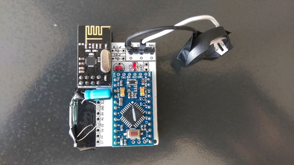
I made a door sensor using a reed switch with both normally open and normally closed pins, and connected them to D2 and D3 (+ ground on the other side connected, as on my last picture above).
In the code I switch the status of the pins in the loop between HIGH/LOW values and set the interrupt on the unconnected pin so the pin is connected to ground only during a very short time (just the time to get out of the sleep mode). I'm supposed to have a very low consumption during deep sleep mode (few microamps). But I have that only when D2 is not connected to ground. If it's connected then it seems I have some current leaking from the INT pin of the NRF24 to the ground through the reed switch, as the board is using 6.5mA.
Without any other change, I made a barbaric cut of the trace near the NRF24 and now the current consumption is around 1.5 µA for both states of the reed switch. For the next boards I will just remove the INT pin of the NRF24, but it would be more simple to have nothing to do :PJust in case this is my sketch (not final, please be tolerant) but I don't think it's really relevant
// Enable debug prints #define MY_DEBUG // Enable and select radio type attached #define MY_RADIO_NRF24 #include <SPI.h> #include <MyConfig.h> #include <MySensors.h> #include <SystemStatus.h> #define SKETCH_NAME "NCA Door Sensor" #define SKETCH_MAJOR_VER "0" #define SKETCH_MINOR_VER "7" #define PRIMARY_CHILD_ID 30 #define SECONDARY_CHILD_ID 4 #define PRIMARY_BUTTON_PIN 2 // Arduino Digital I/O pin for button/reed switch #define SECONDARY_BUTTON_PIN 3 // Arduino Digital I/O pin for button/reed switch #if (PRIMARY_BUTTON_PIN < 2 || PRIMARY_BUTTON_PIN > 3) #error PRIMARY_BUTTON_PIN must be either 2 or 3 for interrupts to work #endif #if (SECONDARY_BUTTON_PIN < 2 || SECONDARY_BUTTON_PIN > 3) #error SECONDARY_BUTTON_PIN must be either 2 or 3 for interrupts to work #endif #if (PRIMARY_BUTTON_PIN == SECONDARY_BUTTON_PIN) #error PRIMARY_BUTTON_PIN and BUTTON_PIN2 cannot be the same #endif #if (PRIMARY_CHILD_ID == SECONDARY_CHILD_ID) #error PRIMARY_CHILD_ID and SECONDARY_CHILD_ID cannot be the same #endif #define MY_NODE_ID 2 #define MY_PARENT_NODE_ID 0 // Change to V_LIGHT if you use S_LIGHT in presentation below MyMessage msg(PRIMARY_CHILD_ID, V_TRIPPED); //MyMessage msg2(SECONDARY_CHILD_ID, V_TRIPPED); // Parameters for VCC measurement const int VccMin = 2400; // Minimum expected Vcc level, in Volts. If you have updated bootloader&BOD you can change to 1.8V here const int VccMax = 3000; // Maximum expected Vcc level, in Volts. SystemStatus vcc(); int LastBatteryPercent = 200; // so we are sure to send the battery level at first check bool isEven = false; // to check+send battery level only for each open+close cycles // This is the activated pin, on which the interrupt is set byte connectedPin = PRIMARY_BUTTON_PIN; byte connectedPinAtLastSending = 0; // Initialized at 0 so we will always send the first time void setup() { // First thing to do: change clock prescaling to 8 to change from 8MHz to 1MHz // of course not necessary if you already have updated fuses and bootloader... #ifndef MY_DEBUG // only if we are not in debug mode, so we can keep the fast baudrate in debug clock_prescale_set (clock_div_8); #endif } void presentation() { // Send the sketch version information to the gateway and Controller sendSketchInfo(SKETCH_NAME, SKETCH_MAJOR_VER "." SKETCH_MINOR_VER); // Register binary input sensor to sensor_node (they will be created as child devices) present(PRIMARY_CHILD_ID, S_DOOR); } // Loop will iterate on changes on the BUTTON_PINs void loop() { // Short delay to allow buttons to properly settle sleep(5); deActivatePin(PRIMARY_BUTTON_PIN); deActivatePin(SECONDARY_BUTTON_PIN); // Check if the previously connected pin is now connected. We do that because it's the most likely to be unconnected now // so it's the best way not to lose any current byte newConnectedPin = GetNonConnectedPin(); if (checkPinIsConnected(connectedPin)) { // If pin is still connected we set back the value to connected pin newConnectedPin = connectedPin; #ifdef MY_DEBUG Serial.println("Connected pin is connected !"); #endif } connectedPin = newConnectedPin; // If connected pin is different that the one during the last sending of status, we send again #ifdef MY_DEBUG Serial.print("Connected pin = "); Serial.println(connectedPin); Serial.print("New Connected pin = "); Serial.println(newConnectedPin); #endif if (connectedPin != connectedPinAtLastSending) { // Value has changed from last transmission, send the updated value send(msg.set(connectedPin==PRIMARY_BUTTON_PIN ? 1 : 0)); connectedPinAtLastSending = connectedPin; isEven = !isEven; } if (isEven) { // send only every two changes for a full open + close cycle int currentBatteryPercent = SystemStatus().getVCCPercent(VccMin, VccMax); if (currentBatteryPercent != LastBatteryPercent) { LastBatteryPercent = currentBatteryPercent; sendBatteryLevel(currentBatteryPercent); } } #ifdef MY_DEBUG Serial.print("Preparing to sleep, pin "); Serial.println(GetNonConnectedPin()); wait(50); #endif // Activate the non connected pin before setting up interrupt activatePin(GetNonConnectedPin()); // Sleep until something happens with the door sensor sleep(GetNonConnectedPin()-2, CHANGE); } void activatePin(byte pin) { // Set pin as input pinMode(pin, INPUT); // Activate internal pull up digitalWrite(pin, HIGH); } void deActivatePin(byte pin) { // Set back pin as output, low pinMode(pin, OUTPUT); digitalWrite(pin, LOW); } // Will check if pin is grounded (returns true) or not boolean checkPinIsConnected(byte pin) { activatePin(pin); // Read value byte valPin = digitalRead(pin); deActivatePin(pin); #ifdef MY_DEBUG Serial.print("checkPinIsConnected pin = "); Serial.print(pin); Serial.print(", value = "); Serial.println(valPin); #endif return valPin != HIGH; } // Returns the pin that is not connected byte GetNonConnectedPin() { return (connectedPin == PRIMARY_BUTTON_PIN) ? SECONDARY_BUTTON_PIN : PRIMARY_BUTTON_PIN; } -
Hello @sundberg84 I have a request for update for your board :)
Can you remove the trace from the INT pin of the NRF24 to the D2 pin of the pro mini ? As interrupt is not used in MySensors for the NRF24, it's not useful while it creates some side effects.I explain you my problem:
I made a door sensor using a reed switch with both normally open and normally closed pins, and connected them to D2 and D3 (+ ground on the other side connected, as on my last picture above).
In the code I switch the status of the pins in the loop between HIGH/LOW values and set the interrupt on the unconnected pin so the pin is connected to ground only during a very short time (just the time to get out of the sleep mode). I'm supposed to have a very low consumption during deep sleep mode (few microamps). But I have that only when D2 is not connected to ground. If it's connected then it seems I have some current leaking from the INT pin of the NRF24 to the ground through the reed switch, as the board is using 6.5mA.
Without any other change, I made a barbaric cut of the trace near the NRF24 and now the current consumption is around 1.5 µA for both states of the reed switch. For the next boards I will just remove the INT pin of the NRF24, but it would be more simple to have nothing to do :PJust in case this is my sketch (not final, please be tolerant) but I don't think it's really relevant
// Enable debug prints #define MY_DEBUG // Enable and select radio type attached #define MY_RADIO_NRF24 #include <SPI.h> #include <MyConfig.h> #include <MySensors.h> #include <SystemStatus.h> #define SKETCH_NAME "NCA Door Sensor" #define SKETCH_MAJOR_VER "0" #define SKETCH_MINOR_VER "7" #define PRIMARY_CHILD_ID 30 #define SECONDARY_CHILD_ID 4 #define PRIMARY_BUTTON_PIN 2 // Arduino Digital I/O pin for button/reed switch #define SECONDARY_BUTTON_PIN 3 // Arduino Digital I/O pin for button/reed switch #if (PRIMARY_BUTTON_PIN < 2 || PRIMARY_BUTTON_PIN > 3) #error PRIMARY_BUTTON_PIN must be either 2 or 3 for interrupts to work #endif #if (SECONDARY_BUTTON_PIN < 2 || SECONDARY_BUTTON_PIN > 3) #error SECONDARY_BUTTON_PIN must be either 2 or 3 for interrupts to work #endif #if (PRIMARY_BUTTON_PIN == SECONDARY_BUTTON_PIN) #error PRIMARY_BUTTON_PIN and BUTTON_PIN2 cannot be the same #endif #if (PRIMARY_CHILD_ID == SECONDARY_CHILD_ID) #error PRIMARY_CHILD_ID and SECONDARY_CHILD_ID cannot be the same #endif #define MY_NODE_ID 2 #define MY_PARENT_NODE_ID 0 // Change to V_LIGHT if you use S_LIGHT in presentation below MyMessage msg(PRIMARY_CHILD_ID, V_TRIPPED); //MyMessage msg2(SECONDARY_CHILD_ID, V_TRIPPED); // Parameters for VCC measurement const int VccMin = 2400; // Minimum expected Vcc level, in Volts. If you have updated bootloader&BOD you can change to 1.8V here const int VccMax = 3000; // Maximum expected Vcc level, in Volts. SystemStatus vcc(); int LastBatteryPercent = 200; // so we are sure to send the battery level at first check bool isEven = false; // to check+send battery level only for each open+close cycles // This is the activated pin, on which the interrupt is set byte connectedPin = PRIMARY_BUTTON_PIN; byte connectedPinAtLastSending = 0; // Initialized at 0 so we will always send the first time void setup() { // First thing to do: change clock prescaling to 8 to change from 8MHz to 1MHz // of course not necessary if you already have updated fuses and bootloader... #ifndef MY_DEBUG // only if we are not in debug mode, so we can keep the fast baudrate in debug clock_prescale_set (clock_div_8); #endif } void presentation() { // Send the sketch version information to the gateway and Controller sendSketchInfo(SKETCH_NAME, SKETCH_MAJOR_VER "." SKETCH_MINOR_VER); // Register binary input sensor to sensor_node (they will be created as child devices) present(PRIMARY_CHILD_ID, S_DOOR); } // Loop will iterate on changes on the BUTTON_PINs void loop() { // Short delay to allow buttons to properly settle sleep(5); deActivatePin(PRIMARY_BUTTON_PIN); deActivatePin(SECONDARY_BUTTON_PIN); // Check if the previously connected pin is now connected. We do that because it's the most likely to be unconnected now // so it's the best way not to lose any current byte newConnectedPin = GetNonConnectedPin(); if (checkPinIsConnected(connectedPin)) { // If pin is still connected we set back the value to connected pin newConnectedPin = connectedPin; #ifdef MY_DEBUG Serial.println("Connected pin is connected !"); #endif } connectedPin = newConnectedPin; // If connected pin is different that the one during the last sending of status, we send again #ifdef MY_DEBUG Serial.print("Connected pin = "); Serial.println(connectedPin); Serial.print("New Connected pin = "); Serial.println(newConnectedPin); #endif if (connectedPin != connectedPinAtLastSending) { // Value has changed from last transmission, send the updated value send(msg.set(connectedPin==PRIMARY_BUTTON_PIN ? 1 : 0)); connectedPinAtLastSending = connectedPin; isEven = !isEven; } if (isEven) { // send only every two changes for a full open + close cycle int currentBatteryPercent = SystemStatus().getVCCPercent(VccMin, VccMax); if (currentBatteryPercent != LastBatteryPercent) { LastBatteryPercent = currentBatteryPercent; sendBatteryLevel(currentBatteryPercent); } } #ifdef MY_DEBUG Serial.print("Preparing to sleep, pin "); Serial.println(GetNonConnectedPin()); wait(50); #endif // Activate the non connected pin before setting up interrupt activatePin(GetNonConnectedPin()); // Sleep until something happens with the door sensor sleep(GetNonConnectedPin()-2, CHANGE); } void activatePin(byte pin) { // Set pin as input pinMode(pin, INPUT); // Activate internal pull up digitalWrite(pin, HIGH); } void deActivatePin(byte pin) { // Set back pin as output, low pinMode(pin, OUTPUT); digitalWrite(pin, LOW); } // Will check if pin is grounded (returns true) or not boolean checkPinIsConnected(byte pin) { activatePin(pin); // Read value byte valPin = digitalRead(pin); deActivatePin(pin); #ifdef MY_DEBUG Serial.print("checkPinIsConnected pin = "); Serial.print(pin); Serial.print(", value = "); Serial.println(valPin); #endif return valPin != HIGH; } // Returns the pin that is not connected byte GetNonConnectedPin() { return (connectedPin == PRIMARY_BUTTON_PIN) ? SECONDARY_BUTTON_PIN : PRIMARY_BUTTON_PIN; }@Nca78 Thanks. Someone else posted this as well. I will update this Inow rev 9 with some jumper or something.
-
Another real quick question. I have a simple sensor using a DHT11. I have this connected to D3 for signal and power and ground from the right holes. I'm getting an error saying it can't read temp/hum from the DHT. That set up should be right though? I also have a 4.7k ohm resistor in the board for D3 (that's the pin, right?).
-
@chuckconnors - that right, see my post at 110 (https://forum.mysensors.org/topic/2740/easy-newbie-pcb-for-mysensors/110)
I have the dht22 in the prototyping area but have made alot of dht22 attached directly to power/gnd and d3 pin on the mysx connector. Works great. -
@chuckconnors - that right, see my post at 110 (https://forum.mysensors.org/topic/2740/easy-newbie-pcb-for-mysensors/110)
I have the dht22 in the prototyping area but have made alot of dht22 attached directly to power/gnd and d3 pin on the mysx connector. Works great.@sundberg84 Thanks. Another dumb question: What is the difference between the RAW ad the PWR pads and when should I use one rather than the other?
-
If you have unregulated power (RAW) within pro minis on board voltage regulater you can instead of using 5v regulated power use this and the arduino will convert it to 5v. I think the specs are 6-12v (with a varning on that clones can not handle 12v!). So for example if you have a 9v battery you can power everything with connecting this to RAW and GND instead of PWR and GND and the voltage regulater on the pro mini will output 5v for the rest of the PCB. @chuckconnors
-
Just wanted to say great work on this board. I have the first one wired up w/ batteries, 3.3v APM w/led and regulations removed, voltage regulator, dht11 and motion w 3v mod and works wonderfully. Once I get my caliper in, I'll get the right mounting screws, finish my enclosure and post the pics.
-
what is the size of the mounting holes? i don't have a caliper yet to measure this small of a size (ordering on amazon)
@rchamp said:
what is the size of the mounting holes? i don't have a caliper yet to measure this small of a size (ordering on amazon)
I dont have eagles at this computer, so I have to answer you tonight (8 hours) or so...
Thanks for the nice feedback! -
what is the size of the mounting holes? i don't have a caliper yet to measure this small of a size (ordering on amazon)
@rchamp - sorry for later reply, the mounting holes are 2mm or 78.7mil.
Controller: Proxmox VM - Home Assistant
MySensors GW: Arduino Uno - W5100 Ethernet, Gw Shield Nrf24l01+ 2,4Ghz
MySensors GW: Arduino Uno - Gw Shield RFM69, 433mhz
RFLink GW - Arduino Mega + RFLink Shield, 433mhz -
@rchamp - sorry for later reply, the mounting holes are 2mm or 78.7mil.
@sundberg84
awesome thanks! -
Hello, I ordered a second batch from PCBWay, it's ok except some components have a frame on the silkscreen, not very beautiful.
Just wanted to say that it was a pain to cut the 1.6mm PCB so this time I ordered in 0.8mm and it is sooooo easy to cut with regular cissors: no efforts and very clean cut ! So if you plan to cut the right part, order at 1mm or below, you will enjoy the cutting phase :D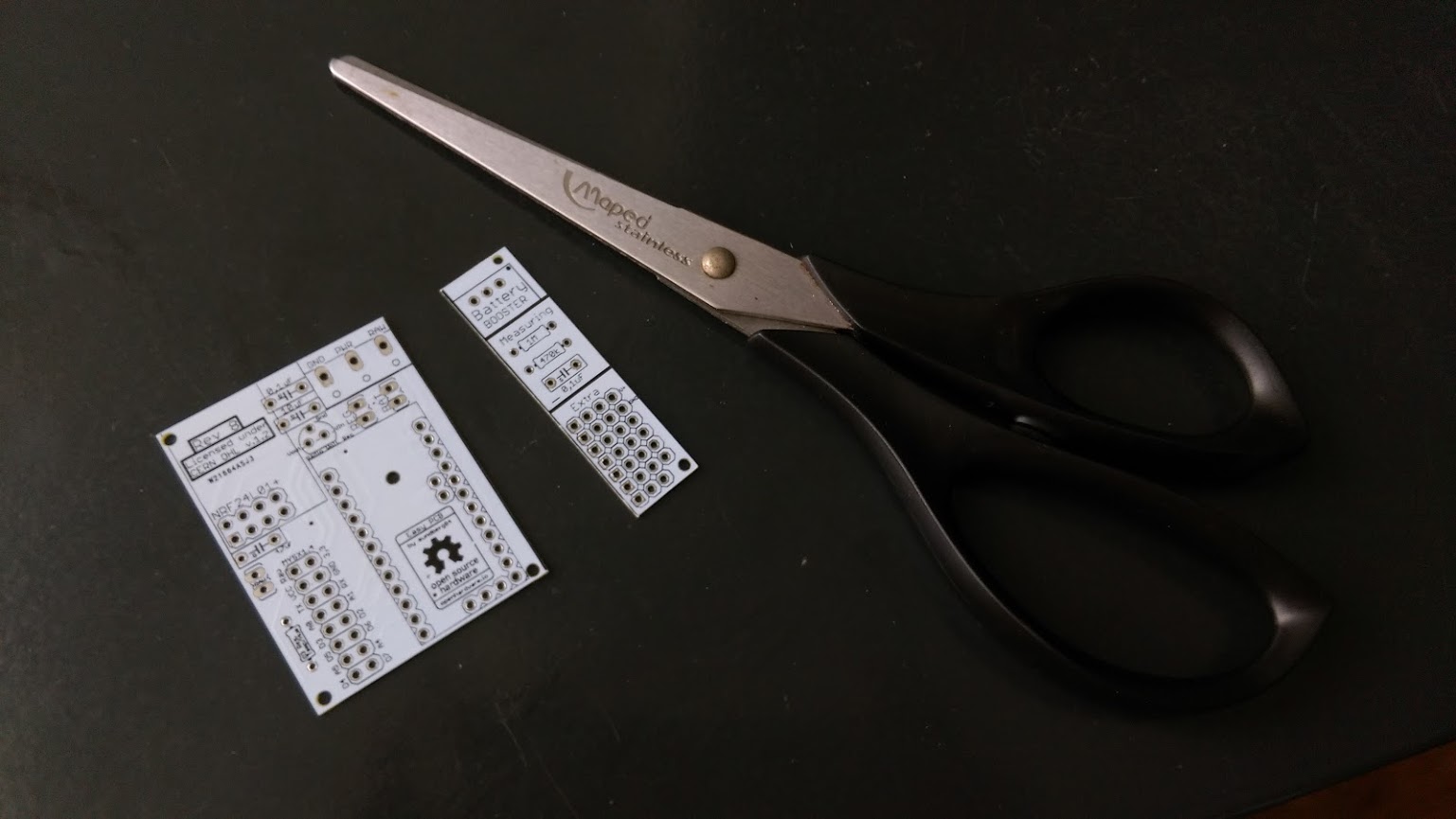
-
Hello, I ordered a second batch from PCBWay, it's ok except some components have a frame on the silkscreen, not very beautiful.
Just wanted to say that it was a pain to cut the 1.6mm PCB so this time I ordered in 0.8mm and it is sooooo easy to cut with regular cissors: no efforts and very clean cut ! So if you plan to cut the right part, order at 1mm or below, you will enjoy the cutting phase :D@Nca78 said:
it's ok except some components have a frame on the silkscreen, not very beautiful.
Sorry, I dont understand what you mean - can you give me a closeup photo? It should be functional AND beautiful :) If the silkscreen overlaps the copper parts this could interfer as well...
you will enjoy the cutting phase
I also learned it the hard way - and since there isnt any high power ciciut it should be ok to order very thin pcbs.
I used a metallic saw for one :persevere: and for some i cut a trace with a knife and bended it until it cracked. -
Just ordered 10 white bords, they look so great :)
-
@Nca78 said:
it's ok except some components have a frame on the silkscreen, not very beautiful.
Sorry, I dont understand what you mean - can you give me a closeup photo? It should be functional AND beautiful :) If the silkscreen overlaps the copper parts this could interfer as well...
you will enjoy the cutting phase
I also learned it the hard way - and since there isnt any high power ciciut it should be ok to order very thin pcbs.
I used a metallic saw for one :persevere: and for some i cut a trace with a knife and bended it until it cracked.@sundberg84 said:
Sorry, I dont understand what you mean - can you give me a closeup photo? It should be functional AND beautiful :) If the silkscreen overlaps the copper parts this could interfer as well...
I fact it's the case only for the "Rev B" and licence text at the top left. No big deal but it was looking better without the frame from DirtyPCB
I also learned it the hard way - and since there isnt any high power ciciut it should be ok to order very thin pcbs.
I used a metallic saw for one :persevere: and for some i cut a trace with a knife and bended it until it cracked.I used the knife too (don't have a metal saw) with the 1.6mm PCBs and it was long and messy. Now it's just like a strong cardboard.
-
I ordered some via DirtyPCB - Ordering via OpenHardware it seems to suggest you are buying Rev4. Says Rev4 under the order button at least.
@Qu3Uk - Yes, and its missleading. Its rev 9 you are ordering but the fourth update on openhardware.io Its no problem ordering from there, I always update those gerber files first.
-
I just wanted to make some suggestions for this board for the possible next revision. I recently ordered a 10 pack (which when I got it ended up being an 11 pack... BONUS BOARD).
When I put together my first board there were some things that I noticed. First, the boards that I got are labeled as rev 8 boards, but there is one small difference from the one shown on the openhardware.io website.

The placement of the 4.7uf capacitor and the raw power connection holes next to the nRF24L01+ socket are reversed. The spot that you have for the 4.7uf capacitor for the nRF24L01+ radio module is just a bit too close to the nRF24 connector. It appears that the capacitor that you chose in your design software was for a ceramic type cap that has a wider hole spacing and is narrower. Choose one for an electrolytic cap and move it away from the nRF24 connector a bit more. This should give the closer hole spacing designed for a small electrolytic cap and leave enough room for it.Similarly the spot you have for the 10uf cap above the regulator appears to also be a design for a ceramic cap with the wider hole spacing. Selecting electrolytics for these should not only give you the correct hole spacing for the electrolytic, but it should also better mark where the negative lead of the cap needs to go on your silkscreen layer.
The other thing that I wish this had was pads for a SMT AMS1117 regulator. This could be placed in the space under the nRF24 radio or just under the pro mini. You could do this in conjunction with the TO92 style that you have currently placed. It would give the board a bit more flexibility for users. In my parts box, I only had the AMS1117 regulators and not the TO92 style. I have since ordered some of the TO92 style, but having the flexibility for either would have been nice.
Last but not least, it would be nice to have slightly larger corner mounting holes. I don't have many small screws that fit those holes, and I have none that would work with the standoffs that I use.
Other than those few things, it seems like a rock solid board. Thanks for the hard work.
Vera Plus running UI7 with MySensors, Sonoffs and 1-Wire devices
Visit my website for more Bits, Bytes and Ramblings from me: http://dan.bemowski.info/ -
I just wanted to make some suggestions for this board for the possible next revision. I recently ordered a 10 pack (which when I got it ended up being an 11 pack... BONUS BOARD).
When I put together my first board there were some things that I noticed. First, the boards that I got are labeled as rev 8 boards, but there is one small difference from the one shown on the openhardware.io website.
The placement of the 4.7uf capacitor and the raw power connection holes next to the nRF24L01+ socket are reversed. The spot that you have for the 4.7uf capacitor for the nRF24L01+ radio module is just a bit too close to the nRF24 connector. It appears that the capacitor that you chose in your design software was for a ceramic type cap that has a wider hole spacing and is narrower. Choose one for an electrolytic cap and move it away from the nRF24 connector a bit more. This should give the closer hole spacing designed for a small electrolytic cap and leave enough room for it.Similarly the spot you have for the 10uf cap above the regulator appears to also be a design for a ceramic cap with the wider hole spacing. Selecting electrolytics for these should not only give you the correct hole spacing for the electrolytic, but it should also better mark where the negative lead of the cap needs to go on your silkscreen layer.
The other thing that I wish this had was pads for a SMT AMS1117 regulator. This could be placed in the space under the nRF24 radio or just under the pro mini. You could do this in conjunction with the TO92 style that you have currently placed. It would give the board a bit more flexibility for users. In my parts box, I only had the AMS1117 regulators and not the TO92 style. I have since ordered some of the TO92 style, but having the flexibility for either would have been nice.
Last but not least, it would be nice to have slightly larger corner mounting holes. I don't have many small screws that fit those holes, and I have none that would work with the standoffs that I use.
Other than those few things, it seems like a rock solid board. Thanks for the hard work.
@dbemowsk - Hi!
Thank you for great input!Why the difference, is because I released rev 8 but made some last minute changes and forgot to update to rev 8.1.
You pretty much found the difference. It was a couple of days so I didnt think anybody would notice.
Did you order from DirtyPCB? I see not it got the old rev 8 version. I will update openhardware.io!Your suggestions about the 4,7uF cap is exactly what I did in the correct Rev 8 version.
I use electrolytic caps on both 4,7 0,1 and 10 uF without any problems. The G marks ground.I also like the AMS1117 but since its another design than LE33 and MySensors site wuggest LE33 i went with this.
Its a balance between flexibility and easy to use. To many components (like dual voltage regulators) will confuse some new users.I will try to fit in some bigger holes in rev 9 (currently working on it) and see what I can do about the AMS1117 .
Thank you for great input - ill keep it in mind!Br
Andreas -
Hi,
First of all, thank you @sundberg84 for this great PCB. Super easy to work with. Still; there is one question that I haven't been able to figure out yet.
I'm running my pcb as a battery node and want to monitor the battery status. However A0 always returns a value somewhere around 30 +/- 15 - even with brand new batteries. Calculated into voltage, this would mean around 1,04V.
I've checked and double checked that I'm using 470k and 1M resistors.
I've also measured using a multi meter, with incoming value of 3,2 V and outgoing from booster 3,36V.Any ideas that might point me in the right direction for solving this noob issue?