💬 Easy/Newbie PCB for MySensors
-
@ChrisW, I am assuming you are using 3.3v nanos. What are you using for batteries? Where are you measuring your 3.3v? I am assuming that you are measuring it on the radio on pin 2. When using the power booster at 3.3v, first measure the output power of the booster at the pin closest to the RAW input. If you have your 3.3v there, then you need to add a jumper to the regulator pads since you are not using a 3.3v regulator (below the 0.1uf and 10uf capacitors) for the radio. That jumper needs to go between the 2 pads near the flat edge of the regulator silkscreen. You can also jump the lower two pins from the BAT and REG jumpers, that does the same thing. This jumps your 3.3v over to the radio power in. DO NOT put a jumper across BAT. Adding that can ruin your radio if you put more than 3.3v on your PWR in from your batteries. The nRF24L01 radios are sensitive to the power applied to them.
-
Hi guys!
Any suggestions as to why my voltage on 3.3 is either battery voltage (if BAT is short circuited) or 0v if BAT not short circuited. I have the same problem on two boards so I guess I´ve done the same mistake twice and that it´s not H/W error.. This means the radio doesn´t work unless I have brand new batteries or hook it up to USB for programming..
-
@ChrisW, I am assuming you are using 3.3v nanos. What are you using for batteries? Where are you measuring your 3.3v? I am assuming that you are measuring it on the radio on pin 2. When using the power booster at 3.3v, first measure the output power of the booster at the pin closest to the RAW input. If you have your 3.3v there, then you need to add a jumper to the regulator pads since you are not using a 3.3v regulator (below the 0.1uf and 10uf capacitors) for the radio. That jumper needs to go between the 2 pads near the flat edge of the regulator silkscreen. You can also jump the lower two pins from the BAT and REG jumpers, that does the same thing. This jumps your 3.3v over to the radio power in. DO NOT put a jumper across BAT. Adding that can ruin your radio if you put more than 3.3v on your PWR in from your batteries. The nRF24L01 radios are sensitive to the power applied to them.
@dbemowsk , yes I am using the 3.3 nano.
I´m using 2 regular AA batteries 1,5 V. I am measuring on VCC for radio, which should be boosted to 3.3V.
VCC on the left pin layout is 3.3, the 3.3-pin is same as battery.Booster output is 3.3V.
I was unaware of the need for voltage regulator to the radio - since I´m going with 3.3 all the way I never realized this. That´s probably the culprit right there.I´ll try your suggestion tomorrow and see if it works out. Thank you for your time.
@sundberg84 , det är OK, det är inte mitt förstaspråk heller.. ;)
Tack för ett bra nybörjarpaket - väldigt enkelt att få ihop en bra hobbysensor!
Jag misstänker att det är som dbemowsk säger - att jag skulle haft en booster till radion också. -
@dbemowsk , yes I am using the 3.3 nano.
I´m using 2 regular AA batteries 1,5 V. I am measuring on VCC for radio, which should be boosted to 3.3V.
VCC on the left pin layout is 3.3, the 3.3-pin is same as battery.Booster output is 3.3V.
I was unaware of the need for voltage regulator to the radio - since I´m going with 3.3 all the way I never realized this. That´s probably the culprit right there.I´ll try your suggestion tomorrow and see if it works out. Thank you for your time.
@sundberg84 , det är OK, det är inte mitt förstaspråk heller.. ;)
Tack för ett bra nybörjarpaket - väldigt enkelt att få ihop en bra hobbysensor!
Jag misstänker att det är som dbemowsk säger - att jag skulle haft en booster till radion också.@ChrisW - Hi! (Writing in english so all can understand, även om det inte behövs :) )
When you are using 3.3v pro mini and booster with BAT jumper it should not be 3.3v over the radio. This is because the booster generates alot of noice and the radio can handle down to 1.9v without any issues. This is how the PCB was designed due to learning by doing. The radio uses what comes raw from the batteries without booster. Evreything else on the PCB is boosted.
If you are using 2xAA you should be able to run the it beteen 1.9V and 3V (which is most of the batteries since the voltage drops pretty fast below that).
-
@dbemowsk , yes I am using the 3.3 nano.
I´m using 2 regular AA batteries 1,5 V. I am measuring on VCC for radio, which should be boosted to 3.3V.
VCC on the left pin layout is 3.3, the 3.3-pin is same as battery.Booster output is 3.3V.
I was unaware of the need for voltage regulator to the radio - since I´m going with 3.3 all the way I never realized this. That´s probably the culprit right there.I´ll try your suggestion tomorrow and see if it works out. Thank you for your time.
@sundberg84 , det är OK, det är inte mitt förstaspråk heller.. ;)
Tack för ett bra nybörjarpaket - väldigt enkelt att få ihop en bra hobbysensor!
Jag misstänker att det är som dbemowsk säger - att jag skulle haft en booster till radion också.@ChrisW said:
I was unaware of the need for voltage regulator to the radio - since I´m going with 3.3 all the way I never realized this.
That's what I was trying to explain. You do not need the regulator, but the board is set up to use one in the event that you might use a 5 volt nano. That is why I mentioned adding the jumper wire. That is to jumper the input and output pins of where the regulator would normally go IF you were using a 5 volt arduino.

EDIT:
@sundberg84 I think we were typing messages at the same time. I did not realize that the radio could run at that low of a voltage. My method jumps the boosted 3.3 volts over to the radio. Shouldn't adding the 0.1uf and 10uf caps attenuate the noise from the booster when jumping the regulator pins?Vera Plus running UI7 with MySensors, Sonoffs and 1-Wire devices
Visit my website for more Bits, Bytes and Ramblings from me: http://dan.bemowski.info/ -
@ChrisW said:
I was unaware of the need for voltage regulator to the radio - since I´m going with 3.3 all the way I never realized this.
That's what I was trying to explain. You do not need the regulator, but the board is set up to use one in the event that you might use a 5 volt nano. That is why I mentioned adding the jumper wire. That is to jumper the input and output pins of where the regulator would normally go IF you were using a 5 volt arduino.
EDIT:
@sundberg84 I think we were typing messages at the same time. I did not realize that the radio could run at that low of a voltage. My method jumps the boosted 3.3 volts over to the radio. Shouldn't adding the 0.1uf and 10uf caps attenuate the noise from the booster when jumping the regulator pins?@dbemowsk - What I know the booster generates ALOT of noice and are really dependent of the quality of the booster. They are expensive as it is and if you buy the china ones its a big risk you get disturbance to the radio even if you use caps!
I would not recommend to jump the boosted voltage to the radio. It might work in some cases (depending on the hardware) but there is a risk doing it.
Some boosters even generate so much noice that even if you havent it connected directly to the radio it doesnt work.
-
Hiya Sundberg
I think Im having boost converter noise issues from a dodgy ebay batch.
I have soldered up 11 of your boards to date and two are real flaky.
Aside from swapping out the boost converter is there a way to reduce the noise? 0.1UF cap across the radio power/gnd pins? Or across the GND and output pins of the booster itself?
They are kind of expensive so dont want to bin them if I can bodge up a fix...
Thanks,
Matt -
Hiya Sundberg
I think Im having boost converter noise issues from a dodgy ebay batch.
I have soldered up 11 of your boards to date and two are real flaky.
Aside from swapping out the boost converter is there a way to reduce the noise? 0.1UF cap across the radio power/gnd pins? Or across the GND and output pins of the booster itself?
They are kind of expensive so dont want to bin them if I can bodge up a fix...
Thanks,
Matt@Matt - Hi!
This issues has been addressed in the thread before, see if you can find it.
I have had luck with a 0,1 ceramic cap on the booster from out to GND. There is more advances methods to reduce noice which I haven't tried but you can read about them above in the thread somewhere. As you said they are a bit pricey but some boards have I just not been able to fix due to really bad booster and scrapped. -
@Matt - Hi!
This issues has been addressed in the thread before, see if you can find it.
I have had luck with a 0,1 ceramic cap on the booster from out to GND. There is more advances methods to reduce noice which I haven't tried but you can read about them above in the thread somewhere. As you said they are a bit pricey but some boards have I just not been able to fix due to really bad booster and scrapped.@sundberg84 Hiya yep found it, starts with your post 30th June 2016.
To be honest its a bit over my head, inductors. ferrite beads etc. A picture of what to solder where would help.
I did try to 0.1uf cap across OUT and GND but the things still only work for a minute then go silent.
I will desolder existing booster then add a jumper from vin to vout to see how stable they are with a good solid battery supply.
If they are reliable I will order some more boosters, but it seems a bit hit and miss as to reliability...
Unless someone can post a pic or explain (for dummies) how to filter the booster effectively?
I should pull out my scope, which involves tidying my workbench, not a task I undertake lightly....Thanks,
Matt -
@sundberg84 Hiya yep found it, starts with your post 30th June 2016.
To be honest its a bit over my head, inductors. ferrite beads etc. A picture of what to solder where would help.
I did try to 0.1uf cap across OUT and GND but the things still only work for a minute then go silent.
I will desolder existing booster then add a jumper from vin to vout to see how stable they are with a good solid battery supply.
If they are reliable I will order some more boosters, but it seems a bit hit and miss as to reliability...
Unless someone can post a pic or explain (for dummies) how to filter the booster effectively?
I should pull out my scope, which involves tidying my workbench, not a task I undertake lightly....Thanks,
MattHave been doing some investigation of the boost converters, just with my DMM, which doesnt have frequency function.
However it can measure ac ripple. On the working boosters there is a ripple amplitude of around 0.02V. On the flaky ones its anything from 0.03 to 0.05V. So this makes it easy for me to test to converters before comitting them with solder. -
@sundberg84 typically, I try to add the lc-filter to the booster as some of them are very noisy. This is very simple - 3.3µH Axial lead inducter and a large 220µF capacitor (I use the SMD version). This helps to smooth any ripple effect.
-
@alexsh1 I know its a bit historical but could you post a pic or explain how you connect the lc-filter to the boost converter? Having issues here, 0.1uf cap didnt help...
Thanks....@Matt - It was some time ago now i experienced with this... but something like this:
 and to be hones maybe it was from ground (middle pin) to vin (left pin)... try both, cant do any harm. As I said - in most cases it works... I buy 10 and 10 batches and around 7-8 works good enough.
 -
@Matt - It was some time ago now i experienced with this... but something like this:
and to be hones maybe it was from ground (middle pin) to vin (left pin)... try both, cant do any harm. As I said - in most cases it works... I buy 10 and 10 batches and around 7-8 works good enough. -
@sundberg84 thanks, that is how I have soldered the 0.1uF cap but it hasnt improved things.
I was hoping @alexsh1 would be happy to chip in here and show me how to solder the 220uf cap and 3.3uH choke? -
@AWI hey thanks! I especially like this
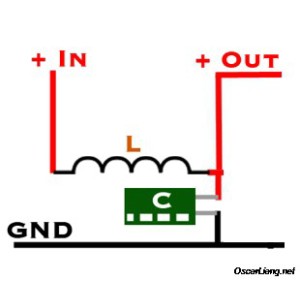
Although.... Something tells me L should be in series on Vout, sureley if it was between BAT and 3.3 voltage weird things would happen....
Might be time to finally try to figure out how to use that cheap old scope in my garage...
Also, as it happens, am just getting in to RC stuff (well for my son, but you know...) -
I have now updated this to Revision 9!
- Bigger mounting holes 2.5mm
- IRQ Jumper from Radio. This makes this trace disabled and D2 can be used for interupts unless jumper is connected.
- BAT and REG jumpers changed positions for better tracing.
- MysX 2,6
- Text on voltage regulater (Vout/Vin/Gnd)
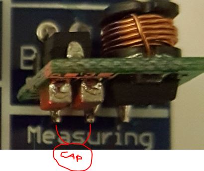
- Bug with G on CAP now on the right side.
- GND and VCC swapped - so you could use a 2 pin block for GND/RAW as well.
- Capacitor to filter the booster output more (optional)
Please wait for PCB house to update to new gerber files before ordering (It should say M.Rev 5 (Manufacturer rev 5) for lastest revision when selecting PCB house)
I have not yet tested this rev... but no major changes so it should be pretty safe.
If you want to be 100% sure, download and order Rev 8.Controller: Proxmox VM - Home Assistant
MySensors GW: Arduino Uno - W5100 Ethernet, Gw Shield Nrf24l01+ 2,4Ghz
MySensors GW: Arduino Uno - Gw Shield RFM69, 433mhz
RFLink GW - Arduino Mega + RFLink Shield, 433mhz -
I have now updated this to Revision 9!
- Bigger mounting holes 2.5mm
- IRQ Jumper from Radio. This makes this trace disabled and D2 can be used for interupts unless jumper is connected.
- BAT and REG jumpers changed positions for better tracing.
- MysX 2,6
- Text on voltage regulater (Vout/Vin/Gnd)
- Bug with G on CAP now on the right side.
- GND and VCC swapped - so you could use a 2 pin block for GND/RAW as well.
- Capacitor to filter the booster output more (optional)
Please wait for PCB house to update to new gerber files before ordering (It should say M.Rev 5 (Manufacturer rev 5) for lastest revision when selecting PCB house)
I have not yet tested this rev... but no major changes so it should be pretty safe.
If you want to be 100% sure, download and order Rev 8.Been a while since I made sensors now - but so what.. ordered 10 pcs in order to try it out :)
-
I have now updated this to Revision 9!
- Bigger mounting holes 2.5mm
- IRQ Jumper from Radio. This makes this trace disabled and D2 can be used for interupts unless jumper is connected.
- BAT and REG jumpers changed positions for better tracing.
- MysX 2,6
- Text on voltage regulater (Vout/Vin/Gnd)
- Bug with G on CAP now on the right side.
- GND and VCC swapped - so you could use a 2 pin block for GND/RAW as well.
- Capacitor to filter the booster output more (optional)
Please wait for PCB house to update to new gerber files before ordering (It should say M.Rev 5 (Manufacturer rev 5) for lastest revision when selecting PCB house)
I have not yet tested this rev... but no major changes so it should be pretty safe.
If you want to be 100% sure, download and order Rev 8.@sundberg84 said:
- Bug with G on CAP now on the right side.
Wait, what?
Missed this. I am using v8 boards. Cant seem to figure out how to search individual threads and 247 posts is a bit much to go through tonight. Will get the DMM out and try to figure it out, but what cap is labelled wrong?
Thanks,
Matt -
@sundberg84 said:
- Bug with G on CAP now on the right side.
Wait, what?
Missed this. I am using v8 boards. Cant seem to figure out how to search individual threads and 247 posts is a bit much to go through tonight. Will get the DMM out and try to figure it out, but what cap is labelled wrong?
Thanks,
Matt@Matt - check the images: https://forum.mysensors.org/topic/2740/easy-newbie-pcb-for-mysensors/197
- Bug with G on CAP now on the right side.
-
@Matt - check the images: https://forum.mysensors.org/topic/2740/easy-newbie-pcb-for-mysensors/197
@sundberg84 cheers, no problem on my boards, multimeter confirms this...