💬 Easy/Newbie PCB for MySensors
-
@BastienVH izz naaiss !!!
-
@sundberg84
I'm waiting your upload with impatience. -
@allmp13 sorry, still no answer from dirtypbs - status: waiting for approval
If you are impatient you can always use the link above... or upload the gerber files. -
I would share the link to my upload, but I don't want to get in the way of sundberg.
I think it's better for sundberg to share his link in the top post and donate whatever he makes to the mysensors project (like he said).
If you can't wait, I'll PM you the link and donate the $1 to mysensors, but it feels wrond to take money (even if I'm giving it away straight afterwards) for something I didn't create myself... -
@sundberg84, @BastienVH Thanks for your reply
-
For those who are feeling lucky: http://dirtypcbs.com/view.php?share=16244&accesskey=14b044f08e0126cb42a9dd9522c568e6
This is my revision 8 and should work just fine but is untested.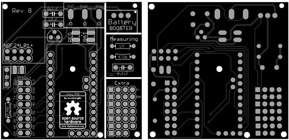
Still no reply from them about my Rev7 upload - and im not expecting it during the weekend so.
-
@dark-nico The nrf24 doesnt go outside the PCB so much, and therefore its smaller. But because of that i had to move the 5 to 3.3volt regulator. Nothing else should be different.
Controller: Proxmox VM - Home Assistant
MySensors GW: Arduino Uno - W5100 Ethernet, Gw Shield Nrf24l01+ 2,4Ghz
MySensors GW: Arduino Uno - Gw Shield RFM69, 433mhz
RFLink GW - Arduino Mega + RFLink Shield, 433mhz -
@dark-nico The nrf24 doesnt go outside the PCB so much, and therefore its smaller. But because of that i had to move the 5 to 3.3volt regulator. Nothing else should be different.
@sundberg84 Thanks for the quick reply.
I've ordered a protopack, I'll let you know when I receive/test it. -
Looks like chinese new year is coming. On Dirtypcbs site: NEW ORDERS SHIP AFTER FEB. 16TH! IT IS SPRING FESTIVAL, CHINA IS CLOSED. YOU SHOULD KNOW THIS, IT IS THE BIGGEST COUNTRY AND ECONOMY IN THE WORLD, THEY MAKE ALLZ YOUR STUFFS! WE WILL NOT ANSWER ANY EMAILS ABOUT ORDERS PLACED IN THIS PERIOD! NO EXCEPTIONS, NO EMERGENCIES, NO NOTHING. A BIG NOTHING BURGER. GOT IT?!?!
-
@sundberg84 thanks for the nice design!
I was not really aware of 'official' and 'unofficial' version (and version at all..) so just after the post of ar91 I followed the link to dirtypcbs and ordered 10 Rev6 boards. I will share my experiences here as soon as they arrive and see if it is worth while to order the rev8's. I like it that it is even smaller withour loosing functionality. -
@sundberg84
Hey, I've been trying to get my boards to work, but without succes so far.
They are revision 7 and have mounted 2 boards with a pro mini and the radio but they're not working.
For the second one I actually checked both the arduino and radio beforehand to see if they functional, which they were.
Now with them mounted, I still get the "radio init fail" message in the arduino serial monitor.
The first board, I mounted with the cap, the second one not yet (I ran out of solder wire).Any ideas how to troubleshoot this?
Should I upload some pictures so you can check the solderjob? -
Hi @BastienVH
Do you use 3.3 or 5v arduino?
How do you power it?
Did you solder the pinheader / jumper?I have rev7 myself, and those works great for me.
-
I have a 3.3v arduino.
At the moment it's powered the FTDI232 connected to my computer.
I will transfer to battery once I'm done.
Do you mean the "BAT" / "REG"?
I haven't soldered that. I'm guessing that's necessary?Also, while I have you hear ;-) , if I want to use the battery measuring, do I have to add the 0.1uF capacitor?
What advantage does it provide?Thanks for your help!
-
If you use the FTDI connector, make sure its the 3.3v and connect it to Gnd/Pwr on the PCB and not Arduino FDTI connector.
You could just exclude those pins and connect a battery directly and use that as power and the FDTI as programmer/serial debug onlyBat or Reg is nessecary!
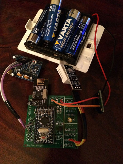
See this picture for battery use: https://www.openhardware.io/view/4/EasyNewbie-PCB-for-MySensors
https://www.openhardware.io/uploads/568ed84b60aa3f8965fbf095/image/3.jpg
All components in the image is needed (except battery measurment).
If you dont want to use booster you need to bypass that one with a wire/jumper (or set the jumper on REG instead of BAT but that kills the logic).The battery doesnt "need" the 0,1uF but see here:https://www.mysensors.org/build/battery
"The tap point could be bypassed with a 0.1 uF capacitor to keep the noise level low, at this otherwise high impedance point. " -
If you use the FTDI connector, make sure its the 3.3v and connect it to Gnd/Pwr on the PCB and not Arduino FDTI connector.
You could just exclude those pins and connect a battery directly and use that as power and the FDTI as programmer/serial debug onlyBat or Reg is nessecary!
See this picture for battery use: https://www.openhardware.io/view/4/EasyNewbie-PCB-for-MySensors
https://www.openhardware.io/uploads/568ed84b60aa3f8965fbf095/image/3.jpg
All components in the image is needed (except battery measurment).
If you dont want to use booster you need to bypass that one with a wire/jumper (or set the jumper on REG instead of BAT but that kills the logic).The battery doesnt "need" the 0,1uF but see here:https://www.mysensors.org/build/battery
"The tap point could be bypassed with a 0.1 uF capacitor to keep the noise level low, at this otherwise high impedance point. "@sundberg84
Thanks for the explanation!
I think I've got it now.
Will test and get back with the results when I've gotten my hands on some more solder wire! -
Hi,
I see you use CERN OHL but I do not find the required files.
Where do you store those?
According to the CERN OHL 1.2 howto, you need to provide the following documentation with your project:
LICENSE.PDF
cern_ohl_v_1_2_howto.pdf
PRODUCT.TXT
CHANGES.TXTPlease check the howto closely for how to use the license, or pick another license. If it is not used according to spec, others don't need to follow it either since it is invalid, so you won't be "protected" by it.
-
@sundberg84
Thanks for the explanation!
I think I've got it now.
Will test and get back with the results when I've gotten my hands on some more solder wire!@BastienVH
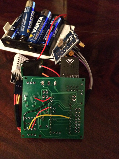
Replying to myself to follow up on my assembly-issues.
I have been able to get the board to work.
I don't have my 0.1µF caps yet, so I just put a little blob of solder in the holes so the current could run through.
Now I've got myself 2 working board. I just have to find a good way to attach my PIR, dallas temp, ... to them.Thanks for the work and help!
-
I'am now finnish with my first rev7 node.
It is a Arduino 5V with DHT-22 and a HC-SR501 sensor.
Good work @sundberg84 for the PCB