💬 Easy/Newbie PCB for MySensors
-
@dakipro - hi!
but they just wont work reliably on lover battery power then 2.8v . Is that the limit?
No, the limit should be (if you have a genuine radio) 1,9v. Im not sure what kind of voltages a clone will manage, but my nodes goes below 2.8v!
I cannot debug using serial adapter, as when I connect it, then pro works fine as it gets 3.3v from the pc.
This should not be a problem - you can power the node from the "normal" way and just connect RX/TX and GND from the ftdi to the arduino ftdi header. I have done this several times.
D2-gnd show 2.5v
The IRQ line from the radio is 2.5v since thats what the radio gets. Im not exactly sure what this does, but in SPI which is what the radio are using, its either HIGH or LOW so 2.5v sounds right since the radio has that voltage. This should not disturb the arduino! This is changed in REV9 so you can disconnect D2 from the radio if wanted. You should not use D2 for any sensor below Rev9.
The led on arduino goes red for 3-4s, then goes off for 2s then again red for 3s, then off...
Sounds like the radio is transmitting... if this goes on and on it can mean the radio isnt getting connected/ack or establish a way to the gateway.
Do you have some suggestions on how I can debug what is going on?
You need to check the debut output (see above)!
Could you describe the issue? Are the node lost from the controller?What is the lowest voltage the batteries can go (with the 3.3v booster)?
1.9v is the minimum to the radio.
0,8v is the minimum for the booster.@sundberg84 I do have the same problem with my setup. As soon as power drops below 2.8 the radio will have problem connecting to gateway. Sometimes it connect after 10-15 tryes. Is there any way to see if nrf sending or any outer way to test stuff? Any ideas are welcome //Håkan
-
@sundberg84 I do have the same problem with my setup. As soon as power drops below 2.8 the radio will have problem connecting to gateway. Sometimes it connect after 10-15 tryes. Is there any way to see if nrf sending or any outer way to test stuff? Any ideas are welcome //Håkan
@keldandorin - are you using a booster as mentioned above?
The problem is in that case noice introduces in the radio from the booster (a known issue). I will in the future try to buy me a oscilloscope and diagnose more... but for now, if you add a "bad/cheap" booster it will be this problem. 2.8v sounds really bad though, and most likley a really bad clone.You have two options.
- Try another booster, and/or try to filter with capacitors.
- Load a new bootloader that can handle lower voltages accoring to link above.
Let me know if I can assist you in any way.
-
@Tommas 5v + 3.3v pro mini there is no example for this. Add your 3.3v pro mini and radio. Connect 5v to raw and put a jumper/connect both reg and bat.
If you want to use to for 2xaa please follow the example.
Dear @sundberg84 !
Thank you! ANd which example should i follow with this modification?
Thanks
T -
There is no right answer since without knowing what you want to do, they could be all wrong or even all correct. :)
Dear gohan!
I would like to power all my nodes from a central power source with 5V . I would like to use 3.3V microcontroller with 3V sensors... because of the voltage drop down caused by the distance (5-15m from the power source). Maybe there will be 1-2 battery powered sensor nodes..
This is my plan.
I dont like using battery. It is too hard for me to optimize the sensors for battery...Best regards
T -
In that case you could also go for rs485 bus. Voltage sources could be also 7 or 9v since you will be using the internal regulator anyway. Most sensor can operate at 5v too, so you don't actually need 3.3v. Optimizing for battery isn't that bad too. Since you are powering the nodes you could also use esp8266 nodes
-
@Tommas 5v + 3.3v pro mini there is no example for this. Add your 3.3v pro mini and radio. Connect 5v to raw and put a jumper/connect both reg and bat.
If you want to use to for 2xaa please follow the example.
-
if you install the voltage regulator in the top left area, you will have the 3.3v ( if I got your question right)
-
@Tommas If you are using 5 volts in and not using a 3.3v pro mini that has the 3.3v regulated output, then you have to add a TO92 case style 3.3v regulator and two capacitors to the board. Here are some that should work. Whatever one you get, make sure you check the pinout against the markings on the board as not all regulators have the same pinout.
http://www.mouser.com/Semiconductors/Power-Management-ICs/LDO-Voltage-Regulators/_/N-5cgac?P=1z0y3jsZ1z0wa2e&pop=88zz -
@Tommas - this is the voltage regulator that the board is designed for so the markings/pinout will be right for you. If you put 5v on the PCB input and use 3.3v pro mini though, the only choise you have is to put 5v on RAW and let the onboard voltage regulator on the PCB regulate it down to 3.3v. The voltage regulator on the PCB only regulate the voltage to the radio and are meant for a 5v input on a 5v pro mini. Using raw means there is no need for the LE33.
-
@keldandorin - are you using a booster as mentioned above?
The problem is in that case noice introduces in the radio from the booster (a known issue). I will in the future try to buy me a oscilloscope and diagnose more... but for now, if you add a "bad/cheap" booster it will be this problem. 2.8v sounds really bad though, and most likley a really bad clone.You have two options.
- Try another booster, and/or try to filter with capacitors.
- Load a new bootloader that can handle lower voltages accoring to link above.
Let me know if I can assist you in any way.
@sundberg84 Is there any way to say if booster is a bad one or not before ordering them?
The one I ordered was the one on shoping list from aliexpress. Will try I capacitator and see if I can get a new booster from kjell&Comany tomorrow just to try. Build a setup on bread bord where I powered radio with 2 AA and got the same result. Got a fju places where I like to put some sensors with no power so realy need to get this working :). Could the radiomodules be bad to? -
@sundberg84 Is there any way to say if booster is a bad one or not before ordering them?
The one I ordered was the one on shoping list from aliexpress. Will try I capacitator and see if I can get a new booster from kjell&Comany tomorrow just to try. Build a setup on bread bord where I powered radio with 2 AA and got the same result. Got a fju places where I like to put some sensors with no power so realy need to get this working :). Could the radiomodules be bad to?@keldandorin - could be a weak clone radio yes.
Just to get your hopes up, I got booster driven nodes all around the place with Nrf24l01+ radio and they works great!
I change battery every 1-1.5 years but as I said, the experience is that the radio - booster needs a good teamwork :)Controller: Proxmox VM - Home Assistant
MySensors GW: Arduino Uno - W5100 Ethernet, Gw Shield Nrf24l01+ 2,4Ghz
MySensors GW: Arduino Uno - Gw Shield RFM69, 433mhz
RFLink GW - Arduino Mega + RFLink Shield, 433mhz -
@keldandorin - could be a weak clone radio yes.
Just to get your hopes up, I got booster driven nodes all around the place with Nrf24l01+ radio and they works great!
I change battery every 1-1.5 years but as I said, the experience is that the radio - booster needs a good teamwork :)@sundberg84 Sounds good, Thats what I'm looking for. Have never worked with tinkers like this befor so everything is new. But this place is great thx for taking time.
-
Sorry, I'm a bit slow and maybe a little off-topic: A quicky:
Can I read somewhere how payment is done when ordering from openhardware.io? On the start page for openhardware.io there is no clue. I've also tried to search this section (easy-newbie-pcb-for-mysensors) for "payment".
Yes, I've read that the "order" is more like a forward of orderinformation to the supplier, but do I really need to order first and after that ask what payment solution is present?
:)
@pellusfromtellus - to get a 100% right answer we ping @hek but I recommend paypal!
-
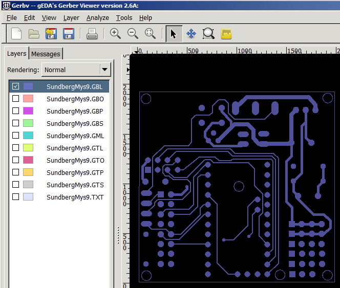
Is there a drilling and outline file available?
-
Is there a drilling and outline file available?
@Paul-Robertson - hi!
Yes, but this is Eagles output gerber files.Drill: SundbergMys9.TXT
Outline can be found in all other files:https://www.pcbway.com/project/share/How_to_generate_Gerber_from_Eagle.html
Hello! It looks like you're interested in this conversation, but you don't have an account yet.
Getting fed up of having to scroll through the same posts each visit? When you register for an account, you'll always come back to exactly where you were before, and choose to be notified of new replies (either via email, or push notification). You'll also be able to save bookmarks and upvote posts to show your appreciation to other community members.
With your input, this post could be even better 💗
Register Login