💬 Easy/Newbie PCB for MySensors
-
@sundberg84 I have a "newby" question about how to use the Extra's part of the board. If I want to connect a DS18B20 sensor per example can I just solder it on the extra area and connect is with some wires to the pinout I need?
Asking this because I did this with the i2c sensor on the board discussed here. having a wire form the extras towards the arduino i2c pins directly. Later I discovered that the i2c pins are also on the board.
So how to deal with this? -
you can add a wire to the I2C pins, in your case you just need a short wire to a digital pin that are just next to the Extra area
@gohan said in 💬 Easy/Newbie PCB for MySensors:
you can add a wire to the I2C pins, in your case you just need a short wire to a digital pin that are just next to the Extra area
Ok. And if attaching a DS18B20 I have a pull up resistor soldered on the board. Than it is also just the digital pin I need from the board? D3 I think?
-
@gohan said in 💬 Easy/Newbie PCB for MySensors:
you can add a wire to the I2C pins, in your case you just need a short wire to a digital pin that are just next to the Extra area
Ok. And if attaching a DS18B20 I have a pull up resistor soldered on the board. Than it is also just the digital pin I need from the board? D3 I think?
@mr_sensor with a DS18B20 temp sensor I just solder it to the MysX pins (D3, Gnd and VCC) directly and populate the resistor for D3.
-
@mr_sensor with a DS18B20 temp sensor I just solder it to the MysX pins (D3, Gnd and VCC) directly and populate the resistor for D3.
@sundberg84 Yes thanks I did so. But do not get any temp read out? Have al in space also the 4,7 k resistor.
this is my sketch:
[code]


/**
 * The MySensors Arduino library handles the wireless radio link and protocol
 * between your home built sensors/actuators and HA controller of choice.
 * The sensors forms a self healing radio network with optional repeaters. Each
 * repeater and gateway builds a routing tables in EEPROM which keeps track of the
 * network topology allowing messages to be routed to nodes.
 *
 * Created by Henrik Ekblad <henrik.ekblad@mysensors.org>
 * Copyright (C) 2013-2015 Sensnology AB
 * Full contributor list: https://github.com/mysensors/Arduino/graphs/contributors
 *
 * Documentation: http://www.mysensors.org
 * Support Forum: http://forum.mysensors.org
 *
 * This program is free software; you can redistribute it and/or
 * modify it under the terms of the GNU General Public License
 * version 2 as published by the Free Software Foundation.
 *
 *******************************
 *
 * REVISION HISTORY
 * Version 1.0: Henrik EKblad
 * Version 1.1 - 2016-07-20: Converted to MySensors v2.0 and added various improvements - Torben Woltjen (mozzbozz)
 *
 * DESCRIPTION
 * This sketch provides an example of how to implement a humidity/temperature
 *
 * Dallas temperature sensor DS18B20
 *
 * For more information, please visit:
 * http://www.mysensors.org/build/humidity
 *
 HTU21D Humidity Sensor
 Hardware Connections (Breakoutboard to Arduino):
 -VCC = 3.3V
 -GND = GND
 -data  = D3 met pcb 470 uf resistor
 */


#define MY_NODE_ID 4
#define MY_PARENT_NODE_ID 0
#define MY_PARENT_NODE_IS_STATIC

// Enable debug prints
#define MY_DEBUG

// Enable and select radio type attached
#define MY_RADIO_NRF24
//#define MY_RADIO_RFM69
//#define MY_RS485

#include <MySensors.h>
#include <OneWire.h>
//#include <Wire.h>
#include <SPI.h>
#include <DallasTemperature.h>

// Force sending an update of the temperature after n sensor reads, so a controller showing the
// timestamp of the last update doesn't show something like 3 hours in the unlikely case, that
// the value didn't change since;
// i.e. the sensor would force sending an update every UPDATE_INTERVAL*FORCE_UPDATE_N_READS [ms]
//static const uint8_t FORCE_UPDATE_N_READS = 10;

#define COMPARE_TEMP 1 // Send temperature only if changed? 1 = Yes 0 = No

#define ONE_WIRE_BUS 3 // Pin where dallase sensor is connected
#define MAX_ATTACHED_DS18B20 16
//unsigned long SLEEP_TIME = 30000; // Sleep time between reads (in milliseconds)
OneWire oneWire(ONE_WIRE_BUS); // Setup a oneWire instance to communicate with any OneWire devices (not just Maxim/Dallas temperature ICs)
DallasTemperature sensors(&oneWire); // Pass the oneWire reference to Dallas Temperature.
float lastTemperature[MAX_ATTACHED_DS18B20];
int numSensors=0;
bool receivedConfig = false;
bool metric = true;

#define CHILD_ID_TEMP 0
#define CHILD_ID_BATTERY 1
#define CHILD_ID_VOLT 2
//#define CHILD_ID_PRCNT 3

//float lastTemp;
//float lastHum;

//uint8_t nNoUpdatesTemp;
//uint8_t nNoUpdatesHum;
//boolean metric = true;


void presentation()
{
 // Send the Sketch Version Information to the Gateway
  sendSketchInfo("Temperature Sensor", "1.1");

 // Register all sensors to gw (they will be created as child devices)
//  present(CHILD_ID_HUM, S_HUM);
  present(CHILD_ID_TEMP, S_TEMP);
   present(CHILD_ID_BATTERY, S_MULTIMETER);
  //metric = getControllerConfig().isMetric;

// Fetch the number of attached temperature sensors
  numSensors = sensors.getDeviceCount();

  // Present all sensors to controller
  for (int i=0; i<numSensors && i<MAX_ATTACHED_DS18B20; i++) {
     present(i, S_TEMP);
  }

}

int BATTERY_SENSE_PIN = A0;  // select the input pin for the battery sense point

unsigned long SLEEP_TIME = 60000; // Sleep time between reads (in milliseconds)  60000
static int oldBatteryPcnt = 0;


//Create an instance of the object

  MyMessage msg(0,V_TEMP);
//MyMessage msgHum(CHILD_ID_HUM, V_HUM);
MyMessage msgTemp(CHILD_ID_TEMP, V_TEMP);
MyMessage msgBattery(CHILD_ID_BATTERY, V_VOLTAGE);
//MyMessage msgBattery(CHILD_ID_BATTERY, V_PRC);


void setup() {
    // Startup up the OneWire library
  sensors.begin();

     // use the 1.1 V internal reference
#if defined(__AVR_ATmega2560__)
    analogReference(INTERNAL1V1);
#else
    analogReference(INTERNAL);
#endif

// requestTemperatures() will not block current thread
  sensors.setWaitForConversion(false);

}

void loop()
{


// Fetch temperatures from Dallas sensors
  sensors.requestTemperatures();

  // query conversion time and sleep until conversion completed
  int16_t conversionTime = sensors.millisToWaitForConversion(sensors.getResolution());
  // sleep() call can be replaced by wait() call if node need to process incoming messages (or if node is repeater)
  sleep(conversionTime);

  // Read temperatures and send them to controller
  for (int i=0; i<numSensors && i<MAX_ATTACHED_DS18B20; i++) {

    // Fetch and round temperature to one decimal
    float temperature = static_cast<float>(static_cast<int>((getControllerConfig().isMetric?sensors.getTempCByIndex(i):sensors.getTempFByIndex(i)) * 10.)) / 10.;

    // Only send data if temperature has changed and no error
    #if COMPARE_TEMP == 1
    if (lastTemperature[i] != temperature && temperature != -127.00 && temperature != 85.00) {
    #else
    if (temperature != -127.00 && temperature != 85.00) {
    #endif

      // Send in the new temperature
      send(msg.setSensor(i).set(temperature,1));
      // Save new temperatures for next compare
      lastTemperature[i]=temperature;
    }
  }


// some delay here
   delay(500);

   // get the battery Voltage

    int sensorValue = analogRead(BATTERY_SENSE_PIN);
    delay(500);
#ifdef MY_DEBUG
    Serial.println(sensorValue);
#endif

    // 1M, 470K divider across battery and using internal ADC ref of 1.1V
    // Sense point is bypassed with 0.1 uF cap to reduce noise at that point
    // ((1e6+470e3)/470e3)*1.1 = Vmax = 3.44 Volts
    // 3.44/1023 = Volts per bit = 0.003363075
    int batteryPcnt = sensorValue / 10;

#ifdef MY_DEBUG
    float batteryV  = sensorValue * 0.003363075;
    Serial.print("Child ID ");
    Serial.print(CHILD_ID_BATTERY);
    Serial.print("Battery Voltage: ");
    Serial.print(batteryV);
    Serial.println(" V");

    Serial.print("Battery Percent: ");
    Serial.print(batteryPcnt);
    Serial.println(" %");
#endif

    if (oldBatteryPcnt != batteryPcnt) {
        // Power up radio after sleep

        sendBatteryLevel(batteryPcnt);
        oldBatteryPcnt = batteryPcnt;
    }

  sleep(SLEEP_TIME); //sleep a bit

}
[/code]```
| / |_ / | ___ _ __ ___ ___ _ __ ___
| |/| | | | _ \ / _ \_ \/ __|/ _ \|_/ __|
| | | | || || | / | | _ \ _ | | \�
|| ||_, |/ ___|| ||/_/|| |/
|__/ 2.2.016 MCO:BGN:INIT NODE,CP=RNNNA---,VER=2.2.0
26 TSM:INIT
28 TSF:WUR:MS=0
34 TSM:INIT:TSP OK
36 TSM:INIT:STATID=4
38 TSF:SID:OK,ID=4
40 TSM:FPAR
43 TSM:FPAR:STATP=0
45 TSM:ID
47 TSM:ID:OK
47 TSM:UPL
53 TSF:MSG:SEND,4-4-0-0,s=255,c=3,t=24,pt=1,l=1,sg=0,ft=0,st=OK:1
67 TSF:MSG:READ,0-0-4,s=255,c=3,t=25,pt=1,l=1,sg=0:1
71 TSF:MSG:PONG RECV,HP=1
75 TSM:UPL:OK
77 TSM:READY:ID=4,PAR=0,DIS=1
116 !TSF:MSG:SEND,4-4-0-0,s=255,c=3,t=15,pt=6,l=2,sg=0,ft=0,st=NACK:0100
2125 TSF:MSG:SEND,4-4-0-0,s=255,c=0,t=17,pt=0,l=5,sg=0,ft=1,st=OK:2.2.0
2138 TSF:MSG:SEND,4-4-0-0,s=255,c=3,t=6,pt=1,l=1,sg=0,ft=0,st=OK:0
4177 TSF:MSG:SEND,4-4-0-0,s=255,c=3,t=11,pt=0,l=18,sg=0,ft=0,st=OK:Temperature Sensor
4196 TSF:MSG:SEND,4-4-0-0,s=255,c=3,t=12,pt=0,l=3,sg=0,ft=0,st=OK:1.1
4214 TSF:MSG:SEND,4-4-0-0,s=0,c=0,t=6,pt=0,l=0,sg=0,ft=0,st=OK:
4227 TSF:MSG:SEND,4-4-0-0,s=1,c=0,t=30,pt=0,l=0,sg=0,ft=0,st=OK:
4235 MCO:REG:REQ
4237 TSF:MSG:SEND,4-4-0-0,s=255,c=3,t=26,pt=1,l=1,sg=0,ft=0,st=OK:2
6246 TSF:MSG:SEND,4-4-0-0,s=255,c=3,t=26,pt=1,l=1,sg=0,ft=0,st=OK:2
8255 TSF:MSG:SEND,4-4-0-0,s=255,c=3,t=26,pt=1,l=1,sg=0,ft=0,st=OK:2
10264 TSF:MSG:SEND,4-4-0-0,s=255,c=3,t=26,pt=1,l=1,sg=0,ft=0,st=OK:2
12273 MCO:BGN:STP
12275 MCO:BGN:INIT OK,TSP=1
12279 MCO:SLP:MS=94,SMS=0,I1=255,M1=255,I2=255,M2=255
12285 TSF:TDI:TSL
12288 MCO:SLP:WUP=-1
12290 TSF:TRI:TSB
915
Child ID 1Battery Voltage: 3.08 V
Battery Percent: 91 %
13297 TSF:MSG:SEND,4-4-0-0,s=255,c=3,t=0,pt=1,l=1,sg=0,ft=0,st=OK:91
13305 MCO:SLP:MS=60000,SMS=0,I1=255,M1=255,I2=255,M2=255
13312 TSF:TDI:TSL
13314 MCO:SLP:WUP=-1
13316 TSF:TRI:TSB
13320 MCO:SLP:MS=94,SMS=0,I1=255,M1=255,I2=255,M2=255
13326 TSF:TDI:TSL
13328 MCO:SLP:WUP=-1
13330 TSF:TRI:TSB
826
Child ID 1Battery Voltage: 2.78 V
Battery Percent: 82 %
14340 TSF:MSG:SEND,4-4-0-0,s=255,c=3,t=0,pt=1,l=1,sg=0,ft=0,st=OK:82
14346 MCO:SLP:MS=60000,SMS=0,I1=255,M1=255,I2=255,M2=255
14352 TSF:TDI:TSL -
@sundberg84 Yes thanks I did so. But do not get any temp read out? Have al in space also the 4,7 k resistor.
this is my sketch:
[code]


/**
 * The MySensors Arduino library handles the wireless radio link and protocol
 * between your home built sensors/actuators and HA controller of choice.
 * The sensors forms a self healing radio network with optional repeaters. Each
 * repeater and gateway builds a routing tables in EEPROM which keeps track of the
 * network topology allowing messages to be routed to nodes.
 *
 * Created by Henrik Ekblad <henrik.ekblad@mysensors.org>
 * Copyright (C) 2013-2015 Sensnology AB
 * Full contributor list: https://github.com/mysensors/Arduino/graphs/contributors
 *
 * Documentation: http://www.mysensors.org
 * Support Forum: http://forum.mysensors.org
 *
 * This program is free software; you can redistribute it and/or
 * modify it under the terms of the GNU General Public License
 * version 2 as published by the Free Software Foundation.
 *
 *******************************
 *
 * REVISION HISTORY
 * Version 1.0: Henrik EKblad
 * Version 1.1 - 2016-07-20: Converted to MySensors v2.0 and added various improvements - Torben Woltjen (mozzbozz)
 *
 * DESCRIPTION
 * This sketch provides an example of how to implement a humidity/temperature
 *
 * Dallas temperature sensor DS18B20
 *
 * For more information, please visit:
 * http://www.mysensors.org/build/humidity
 *
 HTU21D Humidity Sensor
 Hardware Connections (Breakoutboard to Arduino):
 -VCC = 3.3V
 -GND = GND
 -data  = D3 met pcb 470 uf resistor
 */


#define MY_NODE_ID 4
#define MY_PARENT_NODE_ID 0
#define MY_PARENT_NODE_IS_STATIC

// Enable debug prints
#define MY_DEBUG

// Enable and select radio type attached
#define MY_RADIO_NRF24
//#define MY_RADIO_RFM69
//#define MY_RS485

#include <MySensors.h>
#include <OneWire.h>
//#include <Wire.h>
#include <SPI.h>
#include <DallasTemperature.h>

// Force sending an update of the temperature after n sensor reads, so a controller showing the
// timestamp of the last update doesn't show something like 3 hours in the unlikely case, that
// the value didn't change since;
// i.e. the sensor would force sending an update every UPDATE_INTERVAL*FORCE_UPDATE_N_READS [ms]
//static const uint8_t FORCE_UPDATE_N_READS = 10;

#define COMPARE_TEMP 1 // Send temperature only if changed? 1 = Yes 0 = No

#define ONE_WIRE_BUS 3 // Pin where dallase sensor is connected
#define MAX_ATTACHED_DS18B20 16
//unsigned long SLEEP_TIME = 30000; // Sleep time between reads (in milliseconds)
OneWire oneWire(ONE_WIRE_BUS); // Setup a oneWire instance to communicate with any OneWire devices (not just Maxim/Dallas temperature ICs)
DallasTemperature sensors(&oneWire); // Pass the oneWire reference to Dallas Temperature.
float lastTemperature[MAX_ATTACHED_DS18B20];
int numSensors=0;
bool receivedConfig = false;
bool metric = true;

#define CHILD_ID_TEMP 0
#define CHILD_ID_BATTERY 1
#define CHILD_ID_VOLT 2
//#define CHILD_ID_PRCNT 3

//float lastTemp;
//float lastHum;

//uint8_t nNoUpdatesTemp;
//uint8_t nNoUpdatesHum;
//boolean metric = true;


void presentation()
{
 // Send the Sketch Version Information to the Gateway
  sendSketchInfo("Temperature Sensor", "1.1");

 // Register all sensors to gw (they will be created as child devices)
//  present(CHILD_ID_HUM, S_HUM);
  present(CHILD_ID_TEMP, S_TEMP);
   present(CHILD_ID_BATTERY, S_MULTIMETER);
  //metric = getControllerConfig().isMetric;

// Fetch the number of attached temperature sensors
  numSensors = sensors.getDeviceCount();

  // Present all sensors to controller
  for (int i=0; i<numSensors && i<MAX_ATTACHED_DS18B20; i++) {
     present(i, S_TEMP);
  }

}

int BATTERY_SENSE_PIN = A0;  // select the input pin for the battery sense point

unsigned long SLEEP_TIME = 60000; // Sleep time between reads (in milliseconds)  60000
static int oldBatteryPcnt = 0;


//Create an instance of the object

  MyMessage msg(0,V_TEMP);
//MyMessage msgHum(CHILD_ID_HUM, V_HUM);
MyMessage msgTemp(CHILD_ID_TEMP, V_TEMP);
MyMessage msgBattery(CHILD_ID_BATTERY, V_VOLTAGE);
//MyMessage msgBattery(CHILD_ID_BATTERY, V_PRC);


void setup() {
    // Startup up the OneWire library
  sensors.begin();

     // use the 1.1 V internal reference
#if defined(__AVR_ATmega2560__)
    analogReference(INTERNAL1V1);
#else
    analogReference(INTERNAL);
#endif

// requestTemperatures() will not block current thread
  sensors.setWaitForConversion(false);

}

void loop()
{


// Fetch temperatures from Dallas sensors
  sensors.requestTemperatures();

  // query conversion time and sleep until conversion completed
  int16_t conversionTime = sensors.millisToWaitForConversion(sensors.getResolution());
  // sleep() call can be replaced by wait() call if node need to process incoming messages (or if node is repeater)
  sleep(conversionTime);

  // Read temperatures and send them to controller
  for (int i=0; i<numSensors && i<MAX_ATTACHED_DS18B20; i++) {

    // Fetch and round temperature to one decimal
    float temperature = static_cast<float>(static_cast<int>((getControllerConfig().isMetric?sensors.getTempCByIndex(i):sensors.getTempFByIndex(i)) * 10.)) / 10.;

    // Only send data if temperature has changed and no error
    #if COMPARE_TEMP == 1
    if (lastTemperature[i] != temperature && temperature != -127.00 && temperature != 85.00) {
    #else
    if (temperature != -127.00 && temperature != 85.00) {
    #endif

      // Send in the new temperature
      send(msg.setSensor(i).set(temperature,1));
      // Save new temperatures for next compare
      lastTemperature[i]=temperature;
    }
  }


// some delay here
   delay(500);

   // get the battery Voltage

    int sensorValue = analogRead(BATTERY_SENSE_PIN);
    delay(500);
#ifdef MY_DEBUG
    Serial.println(sensorValue);
#endif

    // 1M, 470K divider across battery and using internal ADC ref of 1.1V
    // Sense point is bypassed with 0.1 uF cap to reduce noise at that point
    // ((1e6+470e3)/470e3)*1.1 = Vmax = 3.44 Volts
    // 3.44/1023 = Volts per bit = 0.003363075
    int batteryPcnt = sensorValue / 10;

#ifdef MY_DEBUG
    float batteryV  = sensorValue * 0.003363075;
    Serial.print("Child ID ");
    Serial.print(CHILD_ID_BATTERY);
    Serial.print("Battery Voltage: ");
    Serial.print(batteryV);
    Serial.println(" V");

    Serial.print("Battery Percent: ");
    Serial.print(batteryPcnt);
    Serial.println(" %");
#endif

    if (oldBatteryPcnt != batteryPcnt) {
        // Power up radio after sleep

        sendBatteryLevel(batteryPcnt);
        oldBatteryPcnt = batteryPcnt;
    }

  sleep(SLEEP_TIME); //sleep a bit

}
[/code]```
| / |_ / | ___ _ __ ___ ___ _ __ ___
| |/| | | | _ \ / _ \_ \/ __|/ _ \|_/ __|
| | | | || || | / | | _ \ _ | | \�
|| ||_, |/ ___|| ||/_/|| |/
|__/ 2.2.016 MCO:BGN:INIT NODE,CP=RNNNA---,VER=2.2.0
26 TSM:INIT
28 TSF:WUR:MS=0
34 TSM:INIT:TSP OK
36 TSM:INIT:STATID=4
38 TSF:SID:OK,ID=4
40 TSM:FPAR
43 TSM:FPAR:STATP=0
45 TSM:ID
47 TSM:ID:OK
47 TSM:UPL
53 TSF:MSG:SEND,4-4-0-0,s=255,c=3,t=24,pt=1,l=1,sg=0,ft=0,st=OK:1
67 TSF:MSG:READ,0-0-4,s=255,c=3,t=25,pt=1,l=1,sg=0:1
71 TSF:MSG:PONG RECV,HP=1
75 TSM:UPL:OK
77 TSM:READY:ID=4,PAR=0,DIS=1
116 !TSF:MSG:SEND,4-4-0-0,s=255,c=3,t=15,pt=6,l=2,sg=0,ft=0,st=NACK:0100
2125 TSF:MSG:SEND,4-4-0-0,s=255,c=0,t=17,pt=0,l=5,sg=0,ft=1,st=OK:2.2.0
2138 TSF:MSG:SEND,4-4-0-0,s=255,c=3,t=6,pt=1,l=1,sg=0,ft=0,st=OK:0
4177 TSF:MSG:SEND,4-4-0-0,s=255,c=3,t=11,pt=0,l=18,sg=0,ft=0,st=OK:Temperature Sensor
4196 TSF:MSG:SEND,4-4-0-0,s=255,c=3,t=12,pt=0,l=3,sg=0,ft=0,st=OK:1.1
4214 TSF:MSG:SEND,4-4-0-0,s=0,c=0,t=6,pt=0,l=0,sg=0,ft=0,st=OK:
4227 TSF:MSG:SEND,4-4-0-0,s=1,c=0,t=30,pt=0,l=0,sg=0,ft=0,st=OK:
4235 MCO:REG:REQ
4237 TSF:MSG:SEND,4-4-0-0,s=255,c=3,t=26,pt=1,l=1,sg=0,ft=0,st=OK:2
6246 TSF:MSG:SEND,4-4-0-0,s=255,c=3,t=26,pt=1,l=1,sg=0,ft=0,st=OK:2
8255 TSF:MSG:SEND,4-4-0-0,s=255,c=3,t=26,pt=1,l=1,sg=0,ft=0,st=OK:2
10264 TSF:MSG:SEND,4-4-0-0,s=255,c=3,t=26,pt=1,l=1,sg=0,ft=0,st=OK:2
12273 MCO:BGN:STP
12275 MCO:BGN:INIT OK,TSP=1
12279 MCO:SLP:MS=94,SMS=0,I1=255,M1=255,I2=255,M2=255
12285 TSF:TDI:TSL
12288 MCO:SLP:WUP=-1
12290 TSF:TRI:TSB
915
Child ID 1Battery Voltage: 3.08 V
Battery Percent: 91 %
13297 TSF:MSG:SEND,4-4-0-0,s=255,c=3,t=0,pt=1,l=1,sg=0,ft=0,st=OK:91
13305 MCO:SLP:MS=60000,SMS=0,I1=255,M1=255,I2=255,M2=255
13312 TSF:TDI:TSL
13314 MCO:SLP:WUP=-1
13316 TSF:TRI:TSB
13320 MCO:SLP:MS=94,SMS=0,I1=255,M1=255,I2=255,M2=255
13326 TSF:TDI:TSL
13328 MCO:SLP:WUP=-1
13330 TSF:TRI:TSB
826
Child ID 1Battery Voltage: 2.78 V
Battery Percent: 82 %
14340 TSF:MSG:SEND,4-4-0-0,s=255,c=3,t=0,pt=1,l=1,sg=0,ft=0,st=OK:82
14346 MCO:SLP:MS=60000,SMS=0,I1=255,M1=255,I2=255,M2=255
14352 TSF:TDI:TSL@mr_sensor - it looks ok except the temp sensor. Hard to say but doulecheck your wiring!
-
@mr_sensor - it looks ok except the temp sensor. Hard to say but doulecheck your wiring!
-
@mr_sensor looks right. Upload a sketch without MySensors from the temp library
-
@mr_sensor looks right. Upload a sketch without MySensors from the temp library
@sundberg84 I run the "single" sketch from temp library and this is what I get:
Dallas Temperature IC Control Library Demo Locating devices...Found 0 devices. Parasite power is: OFF Unable to find address for Device 0 Device 0 Address: 0000000000000000 Device 0 Resolution: 0 Requesting temperatures...DONE Temp C: -127.00 Temp F: -196.60 Requesting temperatures...DONE Temp C: -127.00 Temp F: -196.60 Requesting temperatures...DONE Temp C: -127.00 Temp F: -196.60 Requesting temperatures...DONE Temp C: -127.00 Temp F: -196.60 Requesting temperatures...DONE Temp C: -127.00 Temp F: -196.60 Requesting temperatures...DONE Temp C: -127.00 Temp F: -196.60 Requesting temperatures...DONE Temp C: -127.00 Temp F: -196.60 Requesting temperatures...DONE Temp C: -127.00 Temp F: -196.60 Requesting temperatures...DONE Temp C: -127.00 Temp F: -196.60 Requesting temperatures...DONE Temp C: -127.00 Temp F: -196.60 Requesting temperatures...DONE Temp C: -127.00 Temp F: -196.60 -
@sundberg84 I run the "single" sketch from temp library and this is what I get:
Dallas Temperature IC Control Library Demo Locating devices...Found 0 devices. Parasite power is: OFF Unable to find address for Device 0 Device 0 Address: 0000000000000000 Device 0 Resolution: 0 Requesting temperatures...DONE Temp C: -127.00 Temp F: -196.60 Requesting temperatures...DONE Temp C: -127.00 Temp F: -196.60 Requesting temperatures...DONE Temp C: -127.00 Temp F: -196.60 Requesting temperatures...DONE Temp C: -127.00 Temp F: -196.60 Requesting temperatures...DONE Temp C: -127.00 Temp F: -196.60 Requesting temperatures...DONE Temp C: -127.00 Temp F: -196.60 Requesting temperatures...DONE Temp C: -127.00 Temp F: -196.60 Requesting temperatures...DONE Temp C: -127.00 Temp F: -196.60 Requesting temperatures...DONE Temp C: -127.00 Temp F: -196.60 Requesting temperatures...DONE Temp C: -127.00 Temp F: -196.60 Requesting temperatures...DONE Temp C: -127.00 Temp F: -196.60@mr_sensor Lets see your code
-
@sundberg84 I run the "single" sketch from temp library and this is what I get:
Dallas Temperature IC Control Library Demo Locating devices...Found 0 devices. Parasite power is: OFF Unable to find address for Device 0 Device 0 Address: 0000000000000000 Device 0 Resolution: 0 Requesting temperatures...DONE Temp C: -127.00 Temp F: -196.60 Requesting temperatures...DONE Temp C: -127.00 Temp F: -196.60 Requesting temperatures...DONE Temp C: -127.00 Temp F: -196.60 Requesting temperatures...DONE Temp C: -127.00 Temp F: -196.60 Requesting temperatures...DONE Temp C: -127.00 Temp F: -196.60 Requesting temperatures...DONE Temp C: -127.00 Temp F: -196.60 Requesting temperatures...DONE Temp C: -127.00 Temp F: -196.60 Requesting temperatures...DONE Temp C: -127.00 Temp F: -196.60 Requesting temperatures...DONE Temp C: -127.00 Temp F: -196.60 Requesting temperatures...DONE Temp C: -127.00 Temp F: -196.60 Requesting temperatures...DONE Temp C: -127.00 Temp F: -196.60@mr_sensor ok, so either it's not wired correctly (but it looks good), or it's a sensor failure or it's a failure between the sensor and the Arduino.
You can try to measure continuity from sensor to VCC / Gnd and D3 on the atmega.
-
@sundberg84 I run the "single" sketch from temp library and this is what I get:
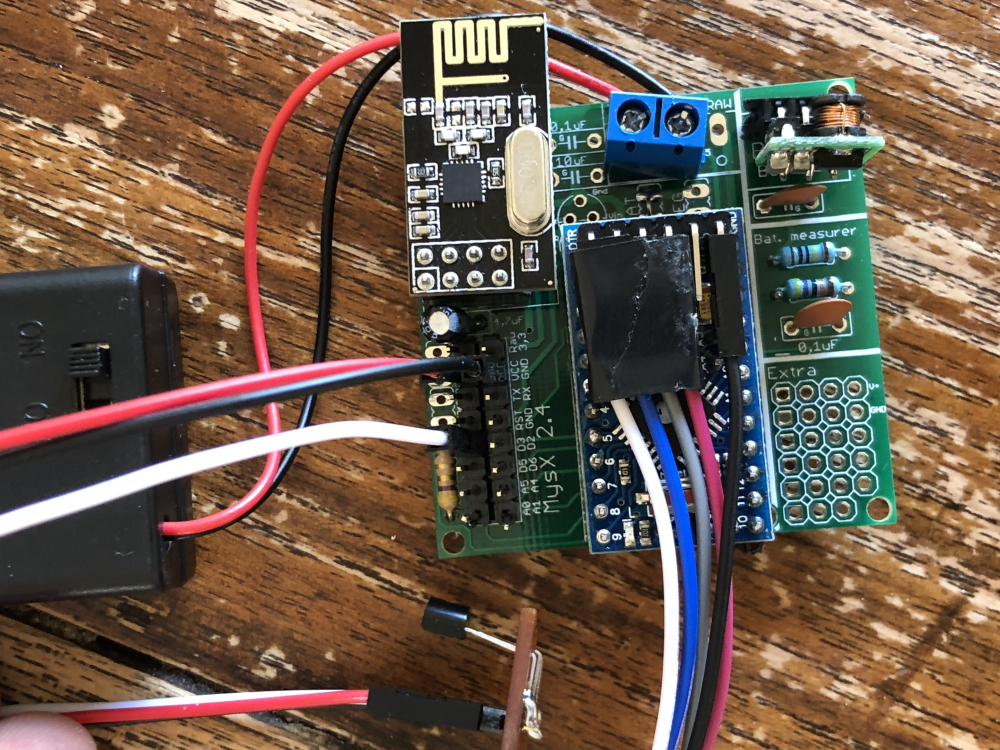
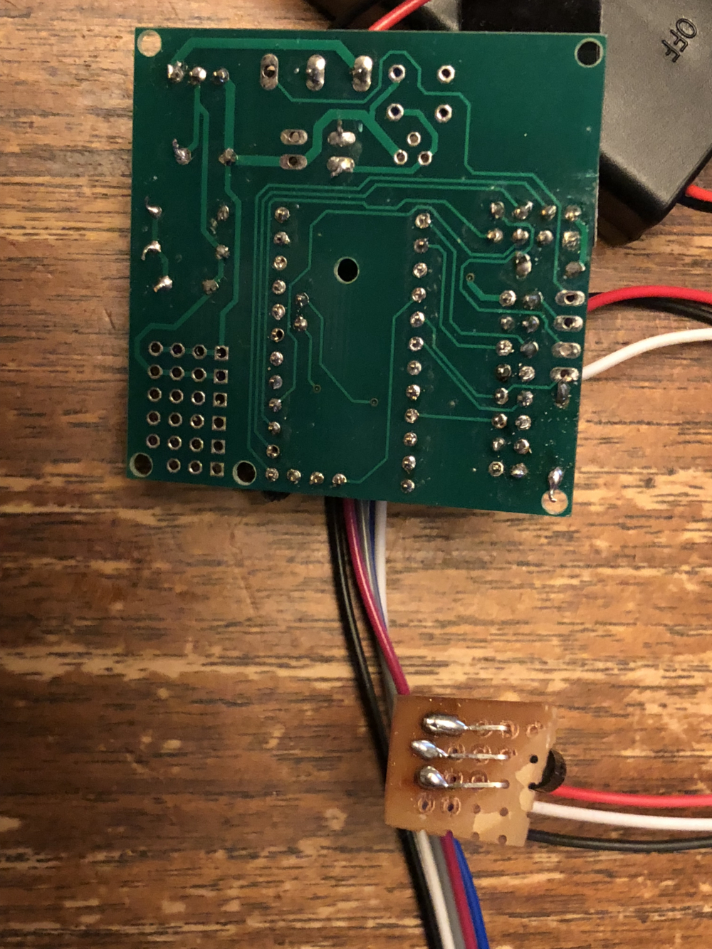
Dallas Temperature IC Control Library Demo Locating devices...Found 0 devices. Parasite power is: OFF Unable to find address for Device 0 Device 0 Address: 0000000000000000 Device 0 Resolution: 0 Requesting temperatures...DONE Temp C: -127.00 Temp F: -196.60 Requesting temperatures...DONE Temp C: -127.00 Temp F: -196.60 Requesting temperatures...DONE Temp C: -127.00 Temp F: -196.60 Requesting temperatures...DONE Temp C: -127.00 Temp F: -196.60 Requesting temperatures...DONE Temp C: -127.00 Temp F: -196.60 Requesting temperatures...DONE Temp C: -127.00 Temp F: -196.60 Requesting temperatures...DONE Temp C: -127.00 Temp F: -196.60 Requesting temperatures...DONE Temp C: -127.00 Temp F: -196.60 Requesting temperatures...DONE Temp C: -127.00 Temp F: -196.60 Requesting temperatures...DONE Temp C: -127.00 Temp F: -196.60 Requesting temperatures...DONE Temp C: -127.00 Temp F: -196.60@mr_sensor And show a pic of the bottom of the board with the sensor.
-
@mr_sensor And show a pic of the bottom of the board with the sensor.
@dbemowsk said in 💬 Easy/Newbie PCB for MySensors:
@mr_sensor And show a pic of the bottom of the board with the sensor.
-
@dbemowsk said in 💬 Easy/Newbie PCB for MySensors:
@mr_sensor And show a pic of the bottom of the board with the sensor.
-
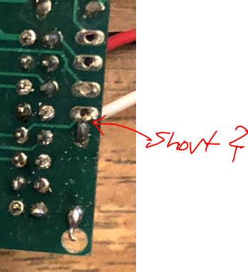
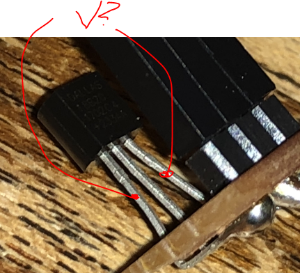
@gohan Not a solder problem I think. This is no short on the board it is just the angel of the picture hiding the gap underneath. :)
tried the same set-up with an other dallas sensor. still the same result.@mr_sensor - still, very strange. I have the exact same setup and it works without issues.
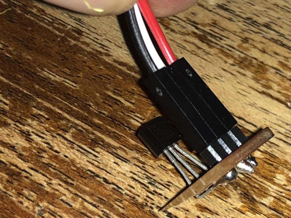
Try to do a continuity test between the middle pin of the sensor (touch the leg, not any solder-point) and D3 on the atmega328 chip (Do not power the node while doing this).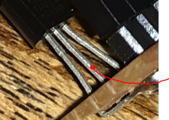
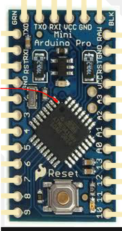
Try to do the same continuity test between the middle leg on the sensor and GND + VCC on the PCB.
Also, please report back the voltage between VCC and GND on the sensor. (Same, measure on the legs)
-
@gohan Not a solder problem I think. This is no short on the board it is just the angel of the picture hiding the gap underneath. :)
tried the same set-up with an other dallas sensor. still the same result.@mr_sensor said in 💬 Easy/Newbie PCB for MySensors:
@gohan Not a solder problem I think. This is no short on the board it is just the angel of the picture hiding the gap underneath. :)
tried the same set-up with an other dallas sensor. still the same result.Still you should read and watch a few videos on YouTube about how to make good solder joints, because your board is not really pretty at the moment ;)
It's not difficult to make proper "volcano" shaped solder joints when you have learnt the few tricks you need, and it avoids a lot of hair pulling! -
@mr_sensor - still, very strange. I have the exact same setup and it works without issues.
Try to do a continuity test between the middle pin of the sensor (touch the leg, not any solder-point) and D3 on the atmega328 chip (Do not power the node while doing this).Try to do the same continuity test between the middle leg on the sensor and GND + VCC on the PCB.
Also, please report back the voltage between VCC and GND on the sensor. (Same, measure on the legs)
@sundberg84 I did measure some things. Also replaced the arduino to be sure that it was working (did nt make a difference)
I found 3,3 volt between vcc and gnd on the sensor. Also between the data-pin of the sensor and the arduino there is continuity.
The middle leg on the sensor and GND + VCC on the PCB is not resulting in any continuity(I am not really sure if I did measure it in the right way. It is a bit hard to get gnd + vcc on the multimeter pin together).