💬 Easy/Newbie PCB for MySensors
-
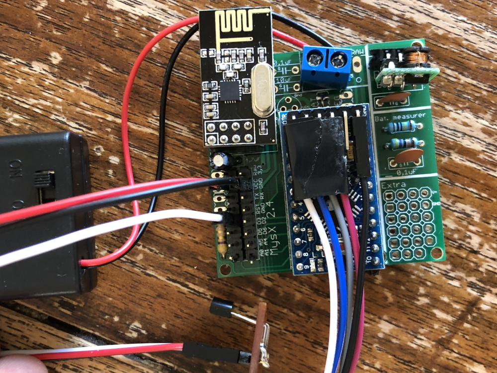
@mr_sensor - it looks ok except the temp sensor. Hard to say but doulecheck your wiring!
-
@mr_sensor looks right. Upload a sketch without MySensors from the temp library
-
@mr_sensor looks right. Upload a sketch without MySensors from the temp library
@sundberg84 I run the "single" sketch from temp library and this is what I get:
Dallas Temperature IC Control Library Demo Locating devices...Found 0 devices. Parasite power is: OFF Unable to find address for Device 0 Device 0 Address: 0000000000000000 Device 0 Resolution: 0 Requesting temperatures...DONE Temp C: -127.00 Temp F: -196.60 Requesting temperatures...DONE Temp C: -127.00 Temp F: -196.60 Requesting temperatures...DONE Temp C: -127.00 Temp F: -196.60 Requesting temperatures...DONE Temp C: -127.00 Temp F: -196.60 Requesting temperatures...DONE Temp C: -127.00 Temp F: -196.60 Requesting temperatures...DONE Temp C: -127.00 Temp F: -196.60 Requesting temperatures...DONE Temp C: -127.00 Temp F: -196.60 Requesting temperatures...DONE Temp C: -127.00 Temp F: -196.60 Requesting temperatures...DONE Temp C: -127.00 Temp F: -196.60 Requesting temperatures...DONE Temp C: -127.00 Temp F: -196.60 Requesting temperatures...DONE Temp C: -127.00 Temp F: -196.60 -
@sundberg84 I run the "single" sketch from temp library and this is what I get:
Dallas Temperature IC Control Library Demo Locating devices...Found 0 devices. Parasite power is: OFF Unable to find address for Device 0 Device 0 Address: 0000000000000000 Device 0 Resolution: 0 Requesting temperatures...DONE Temp C: -127.00 Temp F: -196.60 Requesting temperatures...DONE Temp C: -127.00 Temp F: -196.60 Requesting temperatures...DONE Temp C: -127.00 Temp F: -196.60 Requesting temperatures...DONE Temp C: -127.00 Temp F: -196.60 Requesting temperatures...DONE Temp C: -127.00 Temp F: -196.60 Requesting temperatures...DONE Temp C: -127.00 Temp F: -196.60 Requesting temperatures...DONE Temp C: -127.00 Temp F: -196.60 Requesting temperatures...DONE Temp C: -127.00 Temp F: -196.60 Requesting temperatures...DONE Temp C: -127.00 Temp F: -196.60 Requesting temperatures...DONE Temp C: -127.00 Temp F: -196.60 Requesting temperatures...DONE Temp C: -127.00 Temp F: -196.60@mr_sensor Lets see your code
-
@sundberg84 I run the "single" sketch from temp library and this is what I get:
Dallas Temperature IC Control Library Demo Locating devices...Found 0 devices. Parasite power is: OFF Unable to find address for Device 0 Device 0 Address: 0000000000000000 Device 0 Resolution: 0 Requesting temperatures...DONE Temp C: -127.00 Temp F: -196.60 Requesting temperatures...DONE Temp C: -127.00 Temp F: -196.60 Requesting temperatures...DONE Temp C: -127.00 Temp F: -196.60 Requesting temperatures...DONE Temp C: -127.00 Temp F: -196.60 Requesting temperatures...DONE Temp C: -127.00 Temp F: -196.60 Requesting temperatures...DONE Temp C: -127.00 Temp F: -196.60 Requesting temperatures...DONE Temp C: -127.00 Temp F: -196.60 Requesting temperatures...DONE Temp C: -127.00 Temp F: -196.60 Requesting temperatures...DONE Temp C: -127.00 Temp F: -196.60 Requesting temperatures...DONE Temp C: -127.00 Temp F: -196.60 Requesting temperatures...DONE Temp C: -127.00 Temp F: -196.60@mr_sensor ok, so either it's not wired correctly (but it looks good), or it's a sensor failure or it's a failure between the sensor and the Arduino.
You can try to measure continuity from sensor to VCC / Gnd and D3 on the atmega.
-
@sundberg84 I run the "single" sketch from temp library and this is what I get:
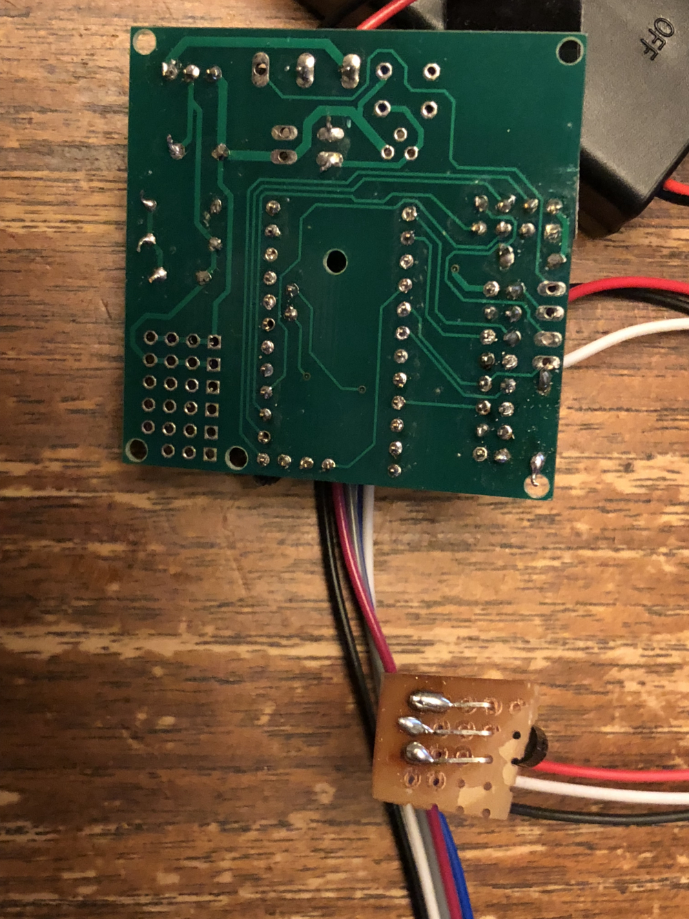
Dallas Temperature IC Control Library Demo Locating devices...Found 0 devices. Parasite power is: OFF Unable to find address for Device 0 Device 0 Address: 0000000000000000 Device 0 Resolution: 0 Requesting temperatures...DONE Temp C: -127.00 Temp F: -196.60 Requesting temperatures...DONE Temp C: -127.00 Temp F: -196.60 Requesting temperatures...DONE Temp C: -127.00 Temp F: -196.60 Requesting temperatures...DONE Temp C: -127.00 Temp F: -196.60 Requesting temperatures...DONE Temp C: -127.00 Temp F: -196.60 Requesting temperatures...DONE Temp C: -127.00 Temp F: -196.60 Requesting temperatures...DONE Temp C: -127.00 Temp F: -196.60 Requesting temperatures...DONE Temp C: -127.00 Temp F: -196.60 Requesting temperatures...DONE Temp C: -127.00 Temp F: -196.60 Requesting temperatures...DONE Temp C: -127.00 Temp F: -196.60 Requesting temperatures...DONE Temp C: -127.00 Temp F: -196.60@mr_sensor And show a pic of the bottom of the board with the sensor.
-
@mr_sensor And show a pic of the bottom of the board with the sensor.
@dbemowsk said in 💬 Easy/Newbie PCB for MySensors:
@mr_sensor And show a pic of the bottom of the board with the sensor.
-
@dbemowsk said in 💬 Easy/Newbie PCB for MySensors:
@mr_sensor And show a pic of the bottom of the board with the sensor.
-
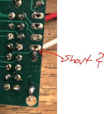
@gohan Not a solder problem I think. This is no short on the board it is just the angel of the picture hiding the gap underneath. :)
tried the same set-up with an other dallas sensor. still the same result.@mr_sensor - still, very strange. I have the exact same setup and it works without issues.
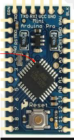
Try to do a continuity test between the middle pin of the sensor (touch the leg, not any solder-point) and D3 on the atmega328 chip (Do not power the node while doing this).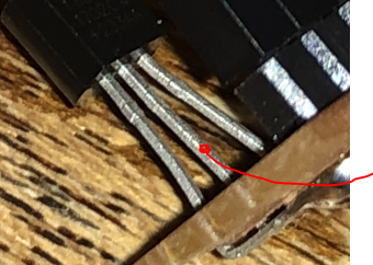
Try to do the same continuity test between the middle leg on the sensor and GND + VCC on the PCB.
Also, please report back the voltage between VCC and GND on the sensor. (Same, measure on the legs)
-
@gohan Not a solder problem I think. This is no short on the board it is just the angel of the picture hiding the gap underneath. :)
tried the same set-up with an other dallas sensor. still the same result.@mr_sensor said in 💬 Easy/Newbie PCB for MySensors:
@gohan Not a solder problem I think. This is no short on the board it is just the angel of the picture hiding the gap underneath. :)
tried the same set-up with an other dallas sensor. still the same result.Still you should read and watch a few videos on YouTube about how to make good solder joints, because your board is not really pretty at the moment ;)
It's not difficult to make proper "volcano" shaped solder joints when you have learnt the few tricks you need, and it avoids a lot of hair pulling! -
@mr_sensor - still, very strange. I have the exact same setup and it works without issues.
Try to do a continuity test between the middle pin of the sensor (touch the leg, not any solder-point) and D3 on the atmega328 chip (Do not power the node while doing this).Try to do the same continuity test between the middle leg on the sensor and GND + VCC on the PCB.
Also, please report back the voltage between VCC and GND on the sensor. (Same, measure on the legs)
@sundberg84 I did measure some things. Also replaced the arduino to be sure that it was working (did nt make a difference)
I found 3,3 volt between vcc and gnd on the sensor. Also between the data-pin of the sensor and the arduino there is continuity.
The middle leg on the sensor and GND + VCC on the PCB is not resulting in any continuity(I am not really sure if I did measure it in the right way. It is a bit hard to get gnd + vcc on the multimeter pin together). -
@sundberg84 I did measure some things. Also replaced the arduino to be sure that it was working (did nt make a difference)
I found 3,3 volt between vcc and gnd on the sensor. Also between the data-pin of the sensor and the arduino there is continuity.
The middle leg on the sensor and GND + VCC on the PCB is not resulting in any continuity(I am not really sure if I did measure it in the right way. It is a bit hard to get gnd + vcc on the multimeter pin together).@mr_sensor - ok, then we can exclude PCB and wiring issues. Next is either software or sensor/pro mini failure. I would re-install the library or try anohter one as first thing to do because you said you have tried another sensor and pro mini right?
-
@mr_sensor - ok, then we can exclude PCB and wiring issues. Next is either software or sensor/pro mini failure. I would re-install the library or try anohter one as first thing to do because you said you have tried another sensor and pro mini right?
@sundberg84 I tried with other libraries, without success. Also changed the sensor for a new one, without any success. Only thing that made me wondering, now the sensor is on 3,3 volt? When looking at the net for samples, etc. some of them refer to 5volt? So could that be the problem here? Not providing 5 volt to the sensor?
-
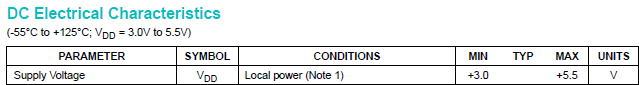
@sundberg84 I tried with other libraries, without success. Also changed the sensor for a new one, without any success. Only thing that made me wondering, now the sensor is on 3,3 volt? When looking at the net for samples, etc. some of them refer to 5volt? So could that be the problem here? Not providing 5 volt to the sensor?
@mr_sensor - no 3.3v is enough:
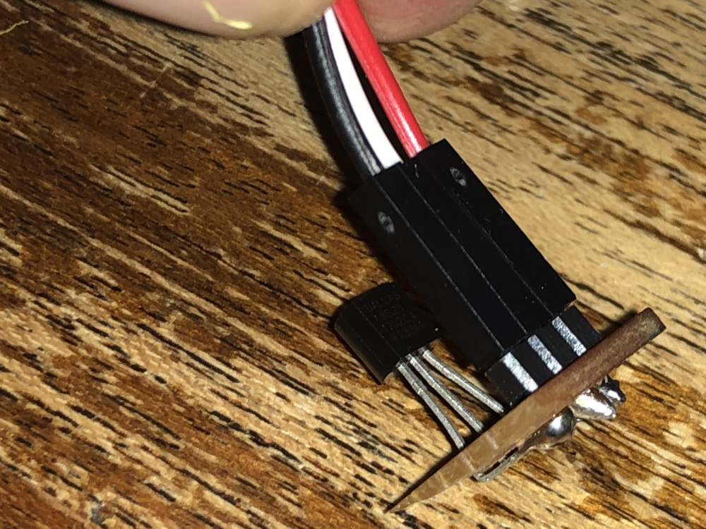
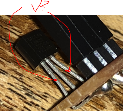
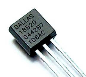
This is really strange... can you confirm it is the right markings on your TO-92 package (actually a temp sensor)?
You could try changing the pin to exclude a pro mini failure (if you have not swapped that one already)
#define ONE_WIRE_BUS 3 // Pin where dallase sensor is connected
#define MAX_ATTACHED_DS18B20 16You can also test my Ds18b20 code from here but you need to change from RFM69 radio to Nrf24l01+ radio,
https://github.com/sundberg84/HomeAutomation/blob/master/Sketches MySensors RFM69 radio/RFM_BeerCooler_Temp/RFM_BeerCooler_Temp.inoI would also try a bare pro mini + the temp sensor + resistor on a breadboard powered with 3.3v from ftdi adapter.
I also need you to doublecheck the resistance on that pull-up resistor:
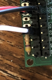
Im having a hard time to see the exact colors but it that is Yellow, Brown, Gold, Gold that means you have a 4.1 ohm resistor to VCC which is pretty much a short and might have broken the temp sensor. Use a 10k or 56k.
Controller: Proxmox VM - Home Assistant
MySensors GW: Arduino Uno - W5100 Ethernet, Gw Shield Nrf24l01+ 2,4Ghz
MySensors GW: Arduino Uno - Gw Shield RFM69, 433mhz
RFLink GW - Arduino Mega + RFLink Shield, 433mhz -
@mr_sensor - no 3.3v is enough:
This is really strange... can you confirm it is the right markings on your TO-92 package (actually a temp sensor)?
You could try changing the pin to exclude a pro mini failure (if you have not swapped that one already)
#define ONE_WIRE_BUS 3 // Pin where dallase sensor is connected
#define MAX_ATTACHED_DS18B20 16You can also test my Ds18b20 code from here but you need to change from RFM69 radio to Nrf24l01+ radio,
https://github.com/sundberg84/HomeAutomation/blob/master/Sketches MySensors RFM69 radio/RFM_BeerCooler_Temp/RFM_BeerCooler_Temp.inoI would also try a bare pro mini + the temp sensor + resistor on a breadboard powered with 3.3v from ftdi adapter.
I also need you to doublecheck the resistance on that pull-up resistor:
Im having a hard time to see the exact colors but it that is Yellow, Brown, Gold, Gold that means you have a 4.1 ohm resistor to VCC which is pretty much a short and might have broken the temp sensor. Use a 10k or 56k.
@sundberg84 Coincidentally I yesterday had a FTDI powered 3v3 Pro-Mini hooked to a RJ11 socket to test and retrieve addresses using the OneWire.h from two plugged DS18B20 devices to add to those in the chain here already, the resistor was 4k7. The chain of now 12 devices also uses a 4k7 and continues to work flawlessly.
-
@mr_sensor - no 3.3v is enough:
This is really strange... can you confirm it is the right markings on your TO-92 package (actually a temp sensor)?
You could try changing the pin to exclude a pro mini failure (if you have not swapped that one already)
#define ONE_WIRE_BUS 3 // Pin where dallase sensor is connected
#define MAX_ATTACHED_DS18B20 16You can also test my Ds18b20 code from here but you need to change from RFM69 radio to Nrf24l01+ radio,
https://github.com/sundberg84/HomeAutomation/blob/master/Sketches MySensors RFM69 radio/RFM_BeerCooler_Temp/RFM_BeerCooler_Temp.inoI would also try a bare pro mini + the temp sensor + resistor on a breadboard powered with 3.3v from ftdi adapter.
I also need you to doublecheck the resistance on that pull-up resistor:
Im having a hard time to see the exact colors but it that is Yellow, Brown, Gold, Gold that means you have a 4.1 ohm resistor to VCC which is pretty much a short and might have broken the temp sensor. Use a 10k or 56k.
@sundberg84 Ok did try with just the bare pro mini + the temp sensor + resistor on a breadboard powered with 3.3v from ftdi adapter.
And guess what? Than I get the temperature reading :) So why is it not working on the board than? I Will check the soldering again and see if I can solder a new board.Dallas Temperature IC Control Library Demo Locating devices...Found 1 devices. Parasite power is: OFF Device 0 Address: 28FF5849011704D8 Device 0 Resolution: 9 Requesting temperatures...DONE Temp C: 21.00 Temp F: 69.80 Requesting temperatures...DONE Temp C: 21.00 Temp F: 69.80 Requesting temperatures...DONE Temp C: 21.00 Temp F: 69.80 Requesting temperatures...DONE Temp C: 21.00 Temp F: 69.80 Requesting temperatures...DONE Temp C: 21.00 Temp F: 69.80 Requesting temperatures...DONE Temp C: 21.00 Temp F: 69.80 Requesting temperatures...DONE ``` So both sensor and arduino are working?