💬 Easy/Newbie PCB for MySensors
-
@zelen I'm not sure. You didn't receive any email? I normally get a email once they are finished and shipped with tracking.
@sundberg84 thank you for clarification. I expected email right after making an order. So, I will wait for finishing production and shipment.
-
I use some of old rev8 boards. I have noticed that I use a ceramic capacitor instead of an electric capacitor compared to the images for the battery measurement. Does it matter? Or should I replace the ceramic capacitor (104) with an electric capacitor?
-
I use some of old rev8 boards. I have noticed that I use a ceramic capacitor instead of an electric capacitor compared to the images for the battery measurement. Does it matter? Or should I replace the ceramic capacitor (104) with an electric capacitor?
@harrdy should work just fine.
-
I use some of old rev8 boards. I have noticed that I use a ceramic capacitor instead of an electric capacitor compared to the images for the battery measurement. Does it matter? Or should I replace the ceramic capacitor (104) with an electric capacitor?
-
Hello @sundberg84, I would like to buy the Easy/Newbie PCB for MySensors but I have a few questions
I want to use it the 5V Arduino Pro mini not the 3V version
I also want to use the battery monitor
Is it ok or should I modify "something"
Also all the pcbs have the battery "expansion: or not?
Thanks, Emmanuel -
Hello @sundberg84, I would like to buy the Easy/Newbie PCB for MySensors but I have a few questions
I want to use it the 5V Arduino Pro mini not the 3V version
I also want to use the battery monitor
Is it ok or should I modify "something"
Also all the pcbs have the battery "expansion: or not?
Thanks, EmmanuelI want to use it the 5V Arduino Pro mini not the 3V version
Then you need to use the nrf24l01+ version, that works fine - the RFM69 version needs a 3.3v Pro Mini only.
I also want to use the battery monitor
As @gohan said - don't use batteries on a 5v node. Use a 3.3v because it will use up your batteries very quickly. See the guides i have on openhardware for different modes on my PCB.
Is it ok or should I modify "something"
Also all the pcbs have the battery "expansion: or not?"something" is hard to understand, you can modify i many different ways depending on what you want to do. All the basic "modifications" can be found if you read the project page on openhardware.io
Controller: Proxmox VM - Home Assistant
MySensors GW: Arduino Uno - W5100 Ethernet, Gw Shield Nrf24l01+ 2,4Ghz
MySensors GW: Arduino Uno - Gw Shield RFM69, 433mhz
RFLink GW - Arduino Mega + RFLink Shield, 433mhz -
I want to use it the 5V Arduino Pro mini not the 3V version
Then you need to use the nrf24l01+ version, that works fine - the RFM69 version needs a 3.3v Pro Mini only.
I also want to use the battery monitor
As @gohan said - don't use batteries on a 5v node. Use a 3.3v because it will use up your batteries very quickly. See the guides i have on openhardware for different modes on my PCB.
Is it ok or should I modify "something"
Also all the pcbs have the battery "expansion: or not?"something" is hard to understand, you can modify i many different ways depending on what you want to do. All the basic "modifications" can be found if you read the project page on openhardware.io
-
@sundberg84 thanks for your response
If I don't care about battery consumption can I still view and use the battery monitor to be alarmed when battery is empty?@manos yes you can.
-
Hello @sundberg84. I watched your video 9+ 'MySensors Battery Node 2xAA - EasyPCB (Nrf24l01+)and Temp Sensor' . I have two questions about this video:
- I noticed you connected the tempsensor to the extra prototype part of the board, but i could not see in the video how you connected signal pin of the sensor to the arduino.
- you added a resistor to D5 Temp/Hum, but you did not add the sensor to the mysX2.4 part of the board. Why is that?
@mister_ik said in 💬 Easy/Newbie PCB for MySensors:
Hello @sundberg84. I watched your video 9+ 'MySensors Battery Node 2xAA - EasyPCB (Nrf24l01+)and Temp Sensor' . I have two questions about this video:
- I noticed you connected the tempsensor to the extra prototype part of the board, but i could not see in the video how you connected signal pin of the sensor to the arduino.
- you added a resistor to D5 Temp/Hum, but you did not add the sensor to the mysX2.4 part of the board. Why is that?
I connect it on the back with a normal wire to D5 resistor input. So both of your observations above are correct.
-
@mister_ik said in 💬 Easy/Newbie PCB for MySensors:
Hello @sundberg84. I watched your video 9+ 'MySensors Battery Node 2xAA - EasyPCB (Nrf24l01+)and Temp Sensor' . I have two questions about this video:
- I noticed you connected the tempsensor to the extra prototype part of the board, but i could not see in the video how you connected signal pin of the sensor to the arduino.
- you added a resistor to D5 Temp/Hum, but you did not add the sensor to the mysX2.4 part of the board. Why is that?
I connect it on the back with a normal wire to D5 resistor input. So both of your observations above are correct.
@sundberg84 yes i thought so, but i want to make sure. I have some Rev 10 boards and i was working on a node for my bathroom with a DHT11 sensor. I had some problems with it, therefore watching your video. But it looks like the step up booster was not working correctly. Unfortunately removing the booster i damaged the board because with a new booster the arduino won't get power any more. So this board only works without the booster (and reg jumper connected). Any idea how long this setup (with removed led on arduino) will last on batteries?
-
@sundberg84 yes i thought so, but i want to make sure. I have some Rev 10 boards and i was working on a node for my bathroom with a DHT11 sensor. I had some problems with it, therefore watching your video. But it looks like the step up booster was not working correctly. Unfortunately removing the booster i damaged the board because with a new booster the arduino won't get power any more. So this board only works without the booster (and reg jumper connected). Any idea how long this setup (with removed led on arduino) will last on batteries?
@mister_ik - well, 2-4 weeks more or less unless you reprogram the fuses and bootloader.
-
@mister_ik - well, 2-4 weeks more or less unless you reprogram the fuses and bootloader.
-
@sundberg84 ooh that is not very long ..i hoped for a couple of months....but then I should consider this board as depreciated and build a new one and use this for development. Thanks for your reaction.
@mister_ik you can always use wired to repair the damaged tracks.
-
@sundberg84, thanks so much for this board, I bought 10 of them. This has made my sensor projects much easier and they look better too! I think I will get some of the RFM69 version next.
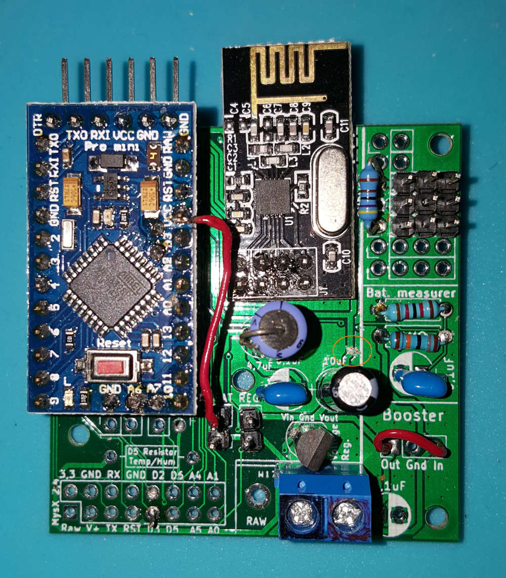
I have a lot of gel lead acid batteries (the 7.2AH type often used in UPSs), and I have been running an earlier prototype off that. I have now just changed over to your board and this is how I modified it to work the way I wanted:
- Cut the track circled
- Hard wired from the regulator side of the battery jumper to VCC on the Pro Mini
- Bridged the booster In to Out
- Changed the battery measuring resistors to 12k/180k for greater range
This enabled me to run the board off 12V, keep an eye on the battery voltage, and run the rest from the LE33 regulator. It seems to be managing so far, with 3 x DS18B20 temperature sensors. I'm monitoring the fridge outside, inside and freezer temperatures with this module.
-
@sundberg84, thanks so much for this board, I bought 10 of them. This has made my sensor projects much easier and they look better too! I think I will get some of the RFM69 version next.
I have a lot of gel lead acid batteries (the 7.2AH type often used in UPSs), and I have been running an earlier prototype off that. I have now just changed over to your board and this is how I modified it to work the way I wanted:
- Cut the track circled
- Hard wired from the regulator side of the battery jumper to VCC on the Pro Mini
- Bridged the booster In to Out
- Changed the battery measuring resistors to 12k/180k for greater range
This enabled me to run the board off 12V, keep an eye on the battery voltage, and run the rest from the LE33 regulator. It seems to be managing so far, with 3 x DS18B20 temperature sensors. I'm monitoring the fridge outside, inside and freezer temperatures with this module.
@ajay100 - Hi!
Really nice to see you found your way of using my PCB, its just the way I want it :)
I tried to follow along here, are you using the LEd33 to convert 12v to 3.3v? I guess you tried RAW and the voltage regulator on your pro mini and found out it was bad due to cheap clones?If you cut the trace just above the volt.reg and put a jumper from REG to Vin on the Volt reg, and added a jumper from Bat (top) to Reg (top) you would also feed everything with whatever comes out from the LE33.
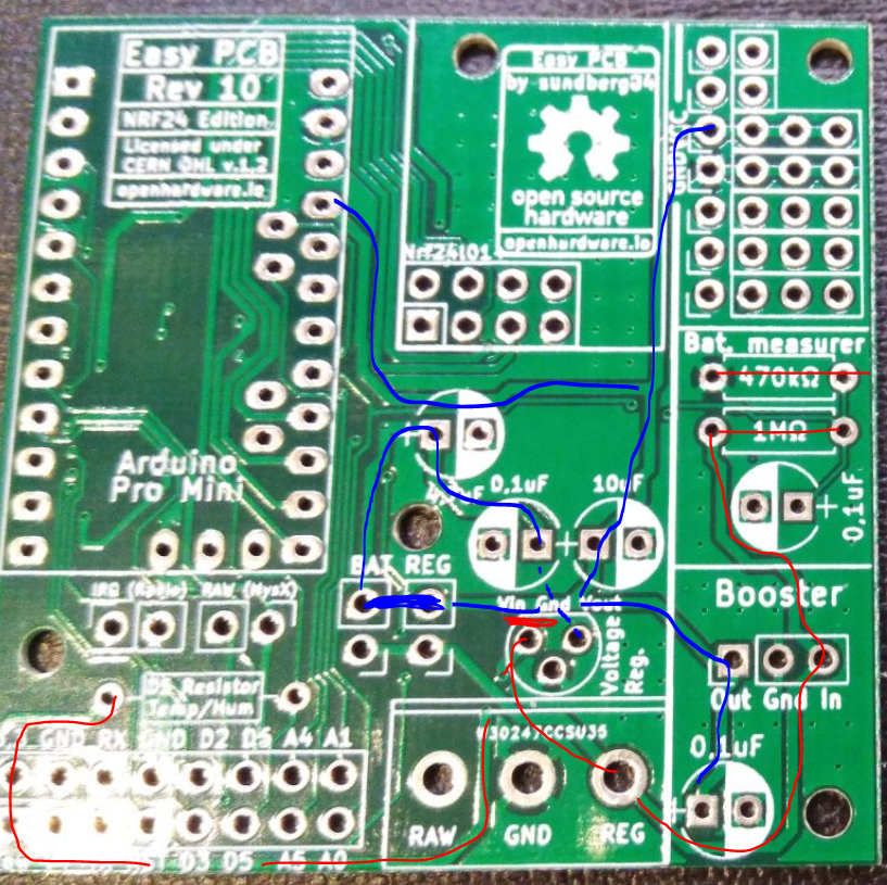 (I think)
 -
@ajay100 - Hi!
Really nice to see you found your way of using my PCB, its just the way I want it :)
I tried to follow along here, are you using the LEd33 to convert 12v to 3.3v? I guess you tried RAW and the voltage regulator on your pro mini and found out it was bad due to cheap clones?If you cut the trace just above the volt.reg and put a jumper from REG to Vin on the Volt reg, and added a jumper from Bat (top) to Reg (top) you would also feed everything with whatever comes out from the LE33.
(I think)@sundberg84, I've just tried it and that is a better solution than mine for running everything from the LE33. Thanks for taking the time to work that out!
Cheers - Andrew