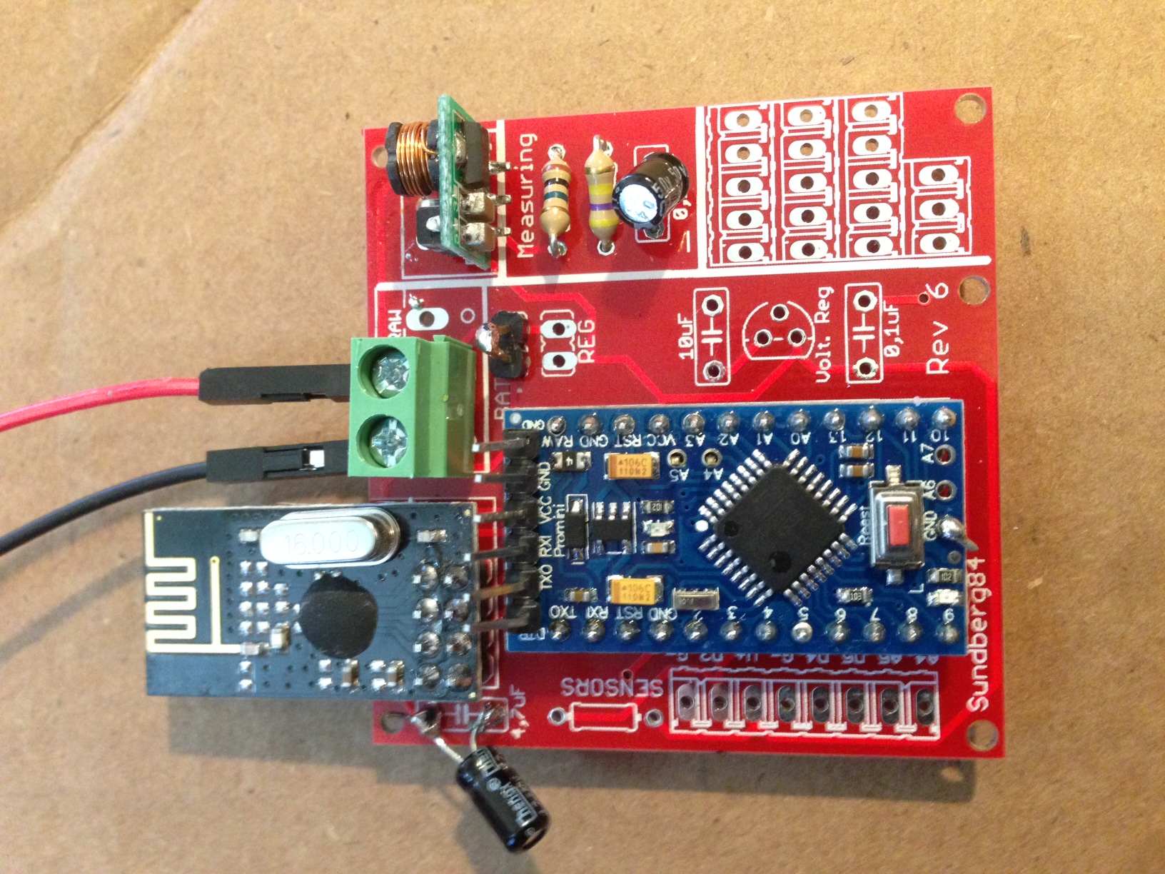
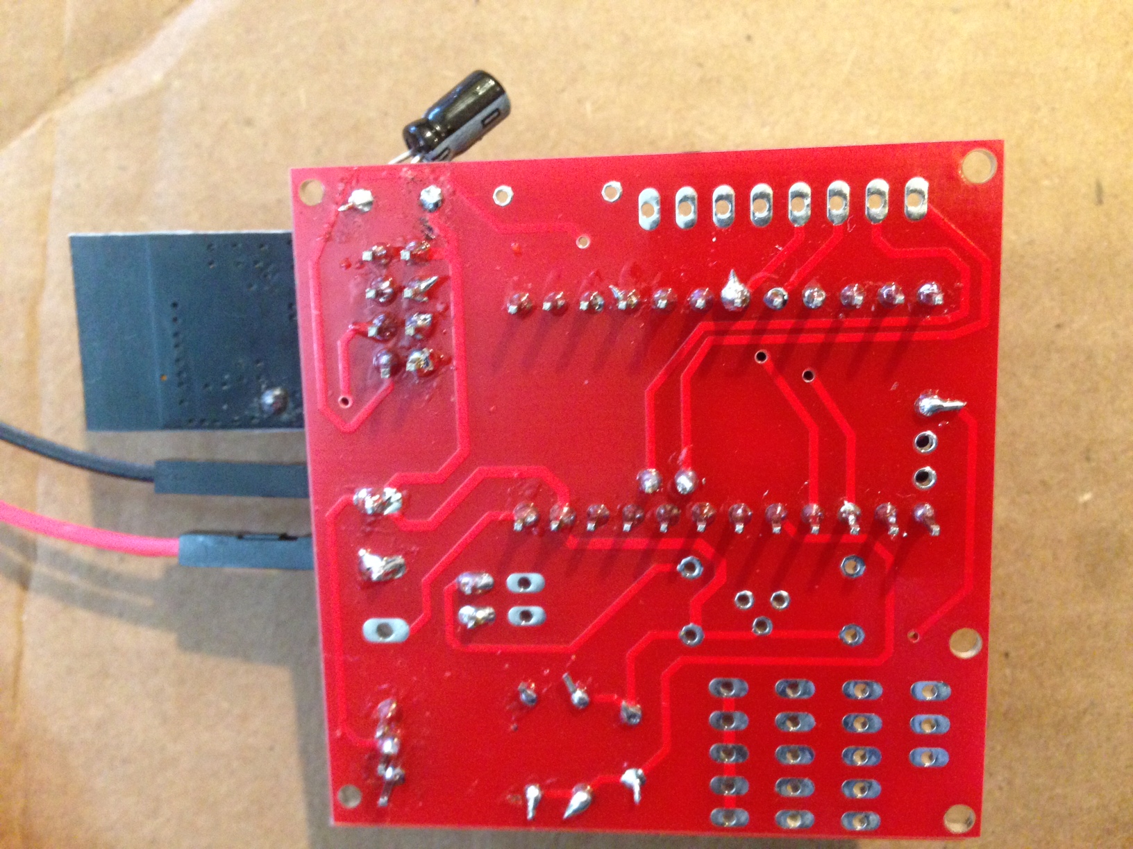
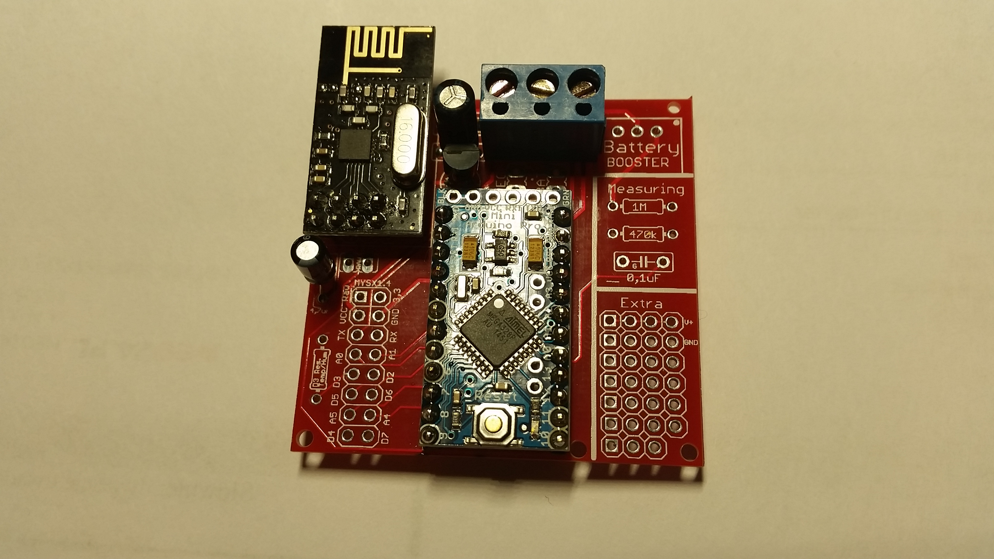
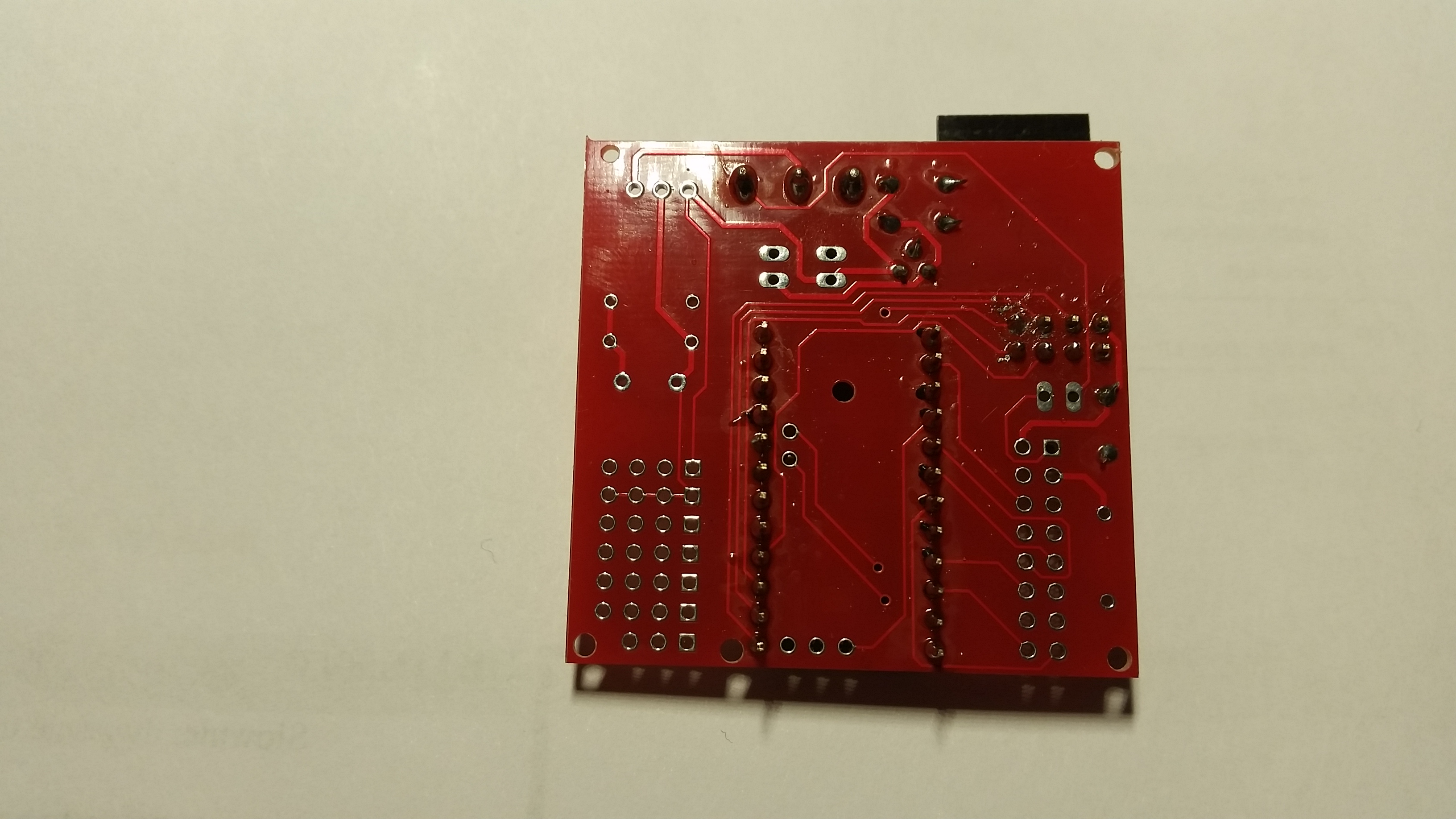
💬 Easy/Newbie PCB for MySensors
-
Yes, you can replace it with a ceramic. There are alot to read about the differences on the net.
-
@Dombo71 - Hi!
The BOM is complete, all capacitors needed and its values are found in the BOM tab.
Since caps are so cheap and common i wont specify any link since you can find theme anywhere. -
Anyone from the Netherlands who ordered a pack of the rev.8 boards? How long did it take to be delivered?
The status update on dirtypcbs.com saysShipped on 27 Jan 2016and I can't wait until I receive them! :) -
Anyone from the Netherlands who ordered a pack of the rev.8 boards? How long did it take to be delivered?
The status update on dirtypcbs.com saysShipped on 27 Jan 2016and I can't wait until I receive them! :) -
Anyone from the Netherlands who ordered a pack of the rev.8 boards? How long did it take to be delivered?
The status update on dirtypcbs.com saysShipped on 27 Jan 2016and I can't wait until I receive them! :)@lxz Chinese New Year Holiday is just over, there seems to be quite a backlog for items ordered in january. It depends on some luck, to Antwerpen took around 6 weeks.
-
I love this PCB. It makes things so much easier. I am having a little problem with the battery version though. I think I've got it wired up right. I've got the jumper. I've got the booster. But, when I plug in a battery (I've tried a 3.7 volt battery, outputting 3.3v - the one from the solar weather station project, and 2 or 4 AA batteries), I get a "Radio Init Fail" message in the serial monitor. Also, the LED at the back, the one near the reset button, does not light brightly. It initially flashes brightly, then nothing.
I've wired it up two different times for the battery setup, and with neither am I getting the live radio.
I am able to get a good radio with the 5v setup.
-
Hi!
@gentrfam
It looks correctly wired. The radio (when bat jumper is selected) is feed directly from the battery, so you need to keep within the specs of the radio (0,9v- 3.6v).
First thing I would do is measure volt over radio. Also measure volt over the arduino. Working backwards can give you a clue where it fails if its a power problem.My wild guess is that either its not a genuine/working NRF radio, or you have a cold/bad solder point on arduino and/or radio.
I always check my radio before soldering them... a while back I counted that I have ordered 33 radios from Ebay and 3 of them was broken so far. So i have a Easy board just for radiocheck loaded with timeaware sketch.
Controller: Proxmox VM - Home Assistant
MySensors GW: Arduino Uno - W5100 Ethernet, Gw Shield Nrf24l01+ 2,4Ghz
MySensors GW: Arduino Uno - Gw Shield RFM69, 433mhz
RFLink GW - Arduino Mega + RFLink Shield, 433mhz -
Hi!
@gentrfam
It looks correctly wired. The radio (when bat jumper is selected) is feed directly from the battery, so you need to keep within the specs of the radio (0,9v- 3.6v).
First thing I would do is measure volt over radio. Also measure volt over the arduino. Working backwards can give you a clue where it fails if its a power problem.My wild guess is that either its not a genuine/working NRF radio, or you have a cold/bad solder point on arduino and/or radio.
I always check my radio before soldering them... a while back I counted that I have ordered 33 radios from Ebay and 3 of them was broken so far. So i have a Easy board just for radiocheck loaded with timeaware sketch.
@sundberg84 Thank you. I checked, and out of the solar-powered battery, I'm actually just out of the radio spec - 3.7-4.0v. I'm going to try with a new radio, and a smaller battery to see if I fried this radio.
In the meantime, I tried to run the battery through an LE33 regulator on a breadboard. (Eventually, I'd like to run the solar-battery through the measuring circuitry on the PCB.) Any idea why the LE33 would be outputting 0.6v?
Thanks for your help. I'm afraid I'm a complete and total noob on this.
-
No, check incoming voltage to the LE33 - is this correct?
Is the caps oriented (ground) correcly? (if you have any).
Broken? -
Hi,
I already received PCB, soldered everything and I'm stuck with reliable radio quality. It works good only when I keep touching antenna on nrf board with my finger. Once I release my finger I've got st=fail.
I've soldered two boards already, tried with two different radios and have same results
I use nrf24L01+ with internal antenna and 5v pro mini, voltage regulator and caps (100nF, 10uF and 4,7uF) as well.Do you have any ideas what can be wrong?
-
I can't wait to get mine, I bet on version 8 :smile: .Fear {display:none;} despite being a noob with electronics.
Although I do have a question, for a 5v pro mini...
Suppose I power this using a 9v battery, assuming connection to the RAW, that means not BAT or REG jumpers ?
And I also wont be able to use the voltage divider to read the voltage.
However It looks like that if there is no jumper in BAT or REG the voltage divider circuit is independent. Would it be possible to re-wire the voltage divider circuit to measure the RAW 9v from the battery?
Does anyone know what happens to the internal voltage regulator when the battery gets week? Would the vcc library get any idea of what is happening to the current internally?
Cheers
-
Hi,
I already received PCB, soldered everything and I'm stuck with reliable radio quality. It works good only when I keep touching antenna on nrf board with my finger. Once I release my finger I've got st=fail.
I've soldered two boards already, tried with two different radios and have same results
I use nrf24L01+ with internal antenna and 5v pro mini, voltage regulator and caps (100nF, 10uF and 4,7uF) as well.Do you have any ideas what can be wrong?
-
@fisher as @sven said - it might be a issue with your nrf... i have seen this issues in several forum posts.
Also, you can try to add a wire from nrf ground to scource ground (and/or try same from voltage regulator) to strengthen your ground connection.@barduino Asuming you are using 5v arduino and using RAW you add a voltage regulator (3.3v) to the radio. You do not need any jumper.
The voltage divider only works from PWR input but if you make a wire from PWR to Vin (right hole) on the booster this should work fine with the voltage divier.The internal voltage regulator can handle 3.35 -12 V (3.3V model) or 5 - 12 V (5V model). Below this the regulator will fail, so you need to set your battery measurment to 0 % 5v 100% = 9v.
This has not been tested by me yet on rev 8 so please share your findings.
Thanks @sundberg84
-
It took a while, but I received the rev8 boards last week. I have already had some time to play with it and it works perfectly on 2x AA. Thanks for sharing your pcb design @sundberg84
-
@chuckconnors Well, it is possible... you can always hard wire/bypass stuff with wires... its possible.
See @BastienVH for minimun req. 3.3v. In bat. operations you feed the radio directly from batteries - less noice and radio can handle down to 0.9V (i think) so its not a problem. You need the booster for sensors and arduino requiers 3.3v to run. You can also feed 3.3v directly to VCC on the PCB if you have that regulated. Then you can just add jumper to reg.If you tell me exactly what you want to do i can help you and explain what you need and how to wire it. With your setup now like you described and you run that on 3v batteries it will be dead within a week.
If you want battery power - you should go with 3.3v arduino (advantage: last longer)
If you have regulated 5v (like from a phone charger) use 5v arduino (advantage: smaller PCB)@sundberg84 said:
@chuckconnors Well, it is possible... you can always hard wire/bypass stuff with wires... its possible.
See @BastienVH for minimun req. 3.3v. In bat. operations you feed the radio directly from batteries - less noice and radio can handle down to 0.9V (i think) so its not a problem. You need the booster for sensors and arduino requiers 3.3v to run. You can also feed 3.3v directly to VCC on the PCB if you have that regulated. Then you can just add jumper to reg.If you tell me exactly what you want to do i can help you and explain what you need and how to wire it. With your setup now like you described and you run that on 3v batteries it will be dead within a week.
If you want battery power - you should go with 3.3v arduino (advantage: last longer)
If you have regulated 5v (like from a phone charger) use 5v arduino (advantage: smaller PCB)@sundberg84 I just got my boards in and am hoping to hook things up this weekend for a simple Temp/Humidity node with a DHT11. The plan is to provide 5V input from an old phone charger. I'd like to wire this directly to the arduino via the GND PWR pads at the top. What jumper do I need to set for this?
Can I just power the radio through the 4.7uF cap via the 3.3V and ground pads on the left side of the board via some wires? Does the radio already have a ground coming from the ground on the arduino? I'm assuming that power would be coming from the arduino regulator. Will this set up work?
Thanks again for your patience.
Hello! It looks like you're interested in this conversation, but you don't have an account yet.
Getting fed up of having to scroll through the same posts each visit? When you register for an account, you'll always come back to exactly where you were before, and choose to be notified of new replies (either via email, or push notification). You'll also be able to save bookmarks and upvote posts to show your appreciation to other community members.
With your input, this post could be even better 💗
Register Login