💬 Easy/Newbie PCB for MySensors
-
@daand83 - haha, easy to forget - I also forgot to post in in my example above (changed now) :)
Only one line of code in a different place... well, hope you found it!@sundberg84 - Indeed missing analogreference. All good now, even got a battery value of 102 % ;)
-
@sundberg84 said:
AMS1117
mmmm I would like to see a board with room for AMS1117 and caps... :)
While waiting for my Newbie PCBs to arrive I have built my own test sensor on a bit of breadboard. Got the new 0,8-3.3v to 3.3v today. My boosters. So, I just cut the trace going from the battery to the rest of the components and arduino and there I connected my booster. VIN directly from bat + and gnd from bat -, Also, everything else that need GND is connected to the same place. I then reconnected the plus power rail to the power coming from the booster. I also moved the radio connection so that if feed directly from the battery. Measurements show me 3.3 v to arduino and other sensors and about 2.9 to the radio directly from batt. Something does not want to work. It is something with the power to the radio. Running sensor on battery only, no booster, works just fine. Running node with everything on vout from the booster, it just won't work. The radio struggles to do something useful but it fails. Running radio on batt and the rest on booster does not work. 'But, if I power the node with power from the serial adapter. the node woks again but only if the battery provide power to the radio at the same time.
Any suggestions? Quite tired, can be messy ;)
@NiklasO - do you have any serial log?
2,9V should be just fine for the radio, but it might freeze with spikes from booster or other power circuit. A 0,1cap from Out to Gnd on the booster might help.Try to remove the booster and verify if the radio works then - if so, its the booster. If not try another radio - we know the radios is very different quality sometimes.
-
Hello, I think @sundberg84 is right, you need some capacitors to filter the noise from the booster, the best is to put the same than those that are on EasyPCB (top of the voltage regulator).
Even if you power the radio directly from the battery, the booster will generate some noise if you use it to power the board, as they have the same GND. -
@NiklasO - do you have any serial log?
2,9V should be just fine for the radio, but it might freeze with spikes from booster or other power circuit. A 0,1cap from Out to Gnd on the booster might help.Try to remove the booster and verify if the radio works then - if so, its the booster. If not try another radio - we know the radios is very different quality sometimes.
@sundberg84 said:
@NiklasO - do you have any serial log?
2,9V should be just fine for the radio, but it might freeze with spikes from booster or other power circuit. A 0,1cap from Out to Gnd on the booster might help.Try to remove the booster and verify if the radio works then - if so, its the booster. If not try another radio - we know the radios is very different quality sometimes.
Thanks for the answers guys!
Everything works as it should when all on battery.
Out to GND already have a cap. The same one the radio use? If it sits between radio vcc and gnd-pin that would be the same as between Vout and GND on the booster, right? I have tried with caps at 0,1 - 100uF. The current one is at 47uF. The serial log say stuff about signing error and other like !TSM:UPL:FAIL when radio on battery and the rest on booster Vout. Reports radio OK at start. All has the same GND.
The multi meter show a quite stable 3.3v output from the booster but I don't have any oscilloscope to see the eventual noise. I have tried different boosters but all are probably the same batch, marked "Canton-power" I think. Also, the radio seem to freeze the Gateway. My sensor tries to communicate with the gateway (I have green, yellow, and red leds connected to both gw and my testsensor). On the sensor the yellow and green blink momentarily and then it greets me with angry red led blinking at me. ;) The gateway does the same ofc but often it freezes with all the three leds constantly on. To make the gateway accept connections again I have to reset it but this does only happen with this troublesome sensor with radio on bat, rest on booster. Other than that the gateway works great with my other sensors (all on battery only for now). -
You have to combine different capacitor values to have some efficient filtering.
If you respect what is implemented on EasyPCB board you should have :- 0.1µF and 10µF as close as possible to the booster output
- your 47µF as close as possible to the GND/VCC of the radio
Location of capacitors is important as if they are far from the radio for example, the wires to the radio act as antenna and will catch noise generated by the booster. So in addition to the capacitors at the right position, try to have wires going to the radio as short as possible.
-
Just wanted to say that my first sensor on this board works great! Measuring passives in place. Worked first try.
On battery, with booster and one DS18B20 temperature sensor.Great work @sundberg84!
-
@sundberg84: I have plan to use your pcb to build ethernet gateway, thus I want to use NRF24L01+ radio with external antenna. In this case it's more than recommended to use external power to supply the radio as pro mini has not enough juice to feed radio properly. Could you please give me some hint how to do it in most elegant way? I think it should be enough to do not solder radio's vcc and gnd pins to pcb, but to connect external power supply to these pins with hardsoldered capacitor. What do you think?
@fisher - that is exactly what I did... i made a external "powerpcb" which i could connect the radio to and the node (Arduino + Ethern module) to. This way I didnt feed the radio from the arduino. Be sure to use a voltage regulator with a good ampere output.
Check this: https://www.openhardware.io/view/207/Mysensors-20-ethernet-gateway-W5100-build
-
@sundberg84: thx for the quick response. I saw your post with external ethernet gateway but I'd like to avoid use of jumper wires and use your newbie psb instead
-
@sundberg84: thx for the quick response. I saw your post with external ethernet gateway but I'd like to avoid use of jumper wires and use your newbie psb instead
@fisher - well, the only option then is to use a 3.3v arduino on my PCB and BAT jumper. Then make sure you have a steady 3.3v on PWR on the PCB. If you have any units (like ethernet module?) that needs 5v you need a step up for this... i guess there are many ways to solve this but I have not tried them so you need to experiment a little.
-
@sundberg84: I think I have to abandon my idea to use Newbie PCB as there is slightly different wiring required for connecting w5100 module. I will solder it on prototype board instead. Thanks for your help
-
@ar91 This is not my upload, but it looks right.
Its not the latest Rev 7 but it Rev6 was working so I think its safe to order.If you wait and order from my upload you are also contributing to MySensors as i will donate that small amount that goes to the author when buying.
@sundberg84
I really like this design. Do you have plans to make a version for the RFM69W radio? Shouldn't be to difficult but with the free version of eagle, I can't edit your design. :unamused: -
@sundberg84
I really like this design. Do you have plans to make a version for the RFM69W radio? Shouldn't be to difficult but with the free version of eagle, I can't edit your design. :unamused:@FotoFieber - that shouldnt be any problem editing. Do you try to open the gerber files, you need to open .sch and .brd
-
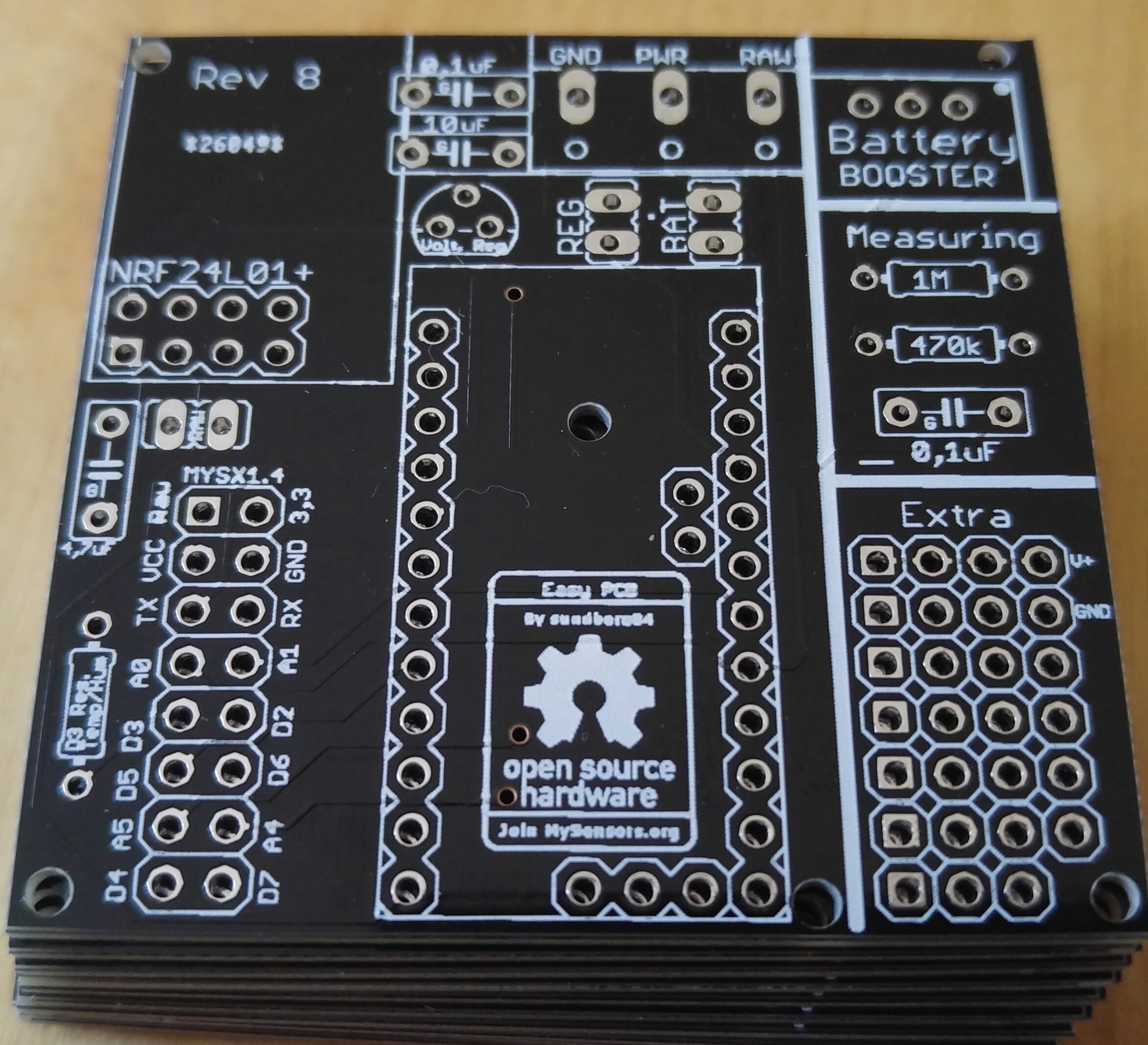
So I have one more flaw to point out in the board that I didn't notice before. I also have a question regarding powering the nano. I'll start with the problem and this is for @sundberg84 . Some weeks back I posted some suggestions and differences that I noticed in the revisions of the boards. This was the pic:

When I posted that, you noted that for the capacitors, the G denotes ground. If you look at the blue board on the right which is the one that I have, you have the G marked on the left leg of the capacitor. If you measure continuity from that pin to the large ground tab for incoming power, you will notice that that is not ground. The one on the right is. Since I got the boards, I have always teeted for continuity for my ground legs, so I haven't had any issues, but for a newbie, which is what the board is geared toward, there could be issues.Now on to my question regarding power. So I am building another node and I am using the 5 volt version of a Recom power module
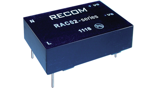 .
.
Seeing that this is a 5 volt output, I would think I should be able to go directly to the 5 volt in on the nano, but what is the best way to wire this if I am using a screw terminal connector to bring my power in? The RAW power pad goes to the regulator input on the nano, and the PWR pad goes to the battery booster which I am not using. I would also guess that I would need to jumper the BAT pads. Would I then too want to remove the regulator from the nano, or won't that matter?Any help is appreciated.
-
So I have one more flaw to point out in the board that I didn't notice before. I also have a question regarding powering the nano. I'll start with the problem and this is for @sundberg84 . Some weeks back I posted some suggestions and differences that I noticed in the revisions of the boards. This was the pic:
When I posted that, you noted that for the capacitors, the G denotes ground. If you look at the blue board on the right which is the one that I have, you have the G marked on the left leg of the capacitor. If you measure continuity from that pin to the large ground tab for incoming power, you will notice that that is not ground. The one on the right is. Since I got the boards, I have always teeted for continuity for my ground legs, so I haven't had any issues, but for a newbie, which is what the board is geared toward, there could be issues.Now on to my question regarding power. So I am building another node and I am using the 5 volt version of a Recom power module
.
Seeing that this is a 5 volt output, I would think I should be able to go directly to the 5 volt in on the nano, but what is the best way to wire this if I am using a screw terminal connector to bring my power in? The RAW power pad goes to the regulator input on the nano, and the PWR pad goes to the battery booster which I am not using. I would also guess that I would need to jumper the BAT pads. Would I then too want to remove the regulator from the nano, or won't that matter?Any help is appreciated.
@dbemowsk - thanks for your unput! I have checked my project and changed the G label.
I will also make an notise on openhardware!You should be able to use that just fine as power. Most people here use HLK-PM01 but this might be a great addition! (Havent seen it before).
Check this thread out: https://forum.mysensors.org/topic/1607/safe-in-wall-ac-to-dc-transformers. You should connect it to PWR and GND with REG jumper short. -
@dbemowsk - thanks for your unput! I have checked my project and changed the G label.
I will also make an notise on openhardware!You should be able to use that just fine as power. Most people here use HLK-PM01 but this might be a great addition! (Havent seen it before).
Check this thread out: https://forum.mysensors.org/topic/1607/safe-in-wall-ac-to-dc-transformers. You should connect it to PWR and GND with REG jumper short.@sundberg84 said:
this might be a great addition! (Havent seen it before).Unfortunately it's not the same price range as HLK with 12$95 from all suppliers linked from their website.
Could still have been nice if it had "physical" advantages compared to HLK but it's bigger and with lower power.
So it's got the safety of a German product left, but HLK is safe enough provided we get a genuine one.Interesting part is the recommended circuit which is similar to the one suggested here for the HLK with input fuse, varistor for use with 230V source and optionnal output capacitor to reduce ripple. No temperature fuse but I suppose with bigger size, lower power and higher quality components it's getting really overkill.
-
I ended up ordering 3 of these. I got them from this site. It wasn't till after I ordered them that I saw a post on here about the HLK-PM01 modules. I see the better advantages of the HLK series, cost being the big one, and will order these in the future as needed, but I am just trying to use up the 3 of these that I have.
I have another project I am working on where I might order some HLK-PM12 modules. I ended up getting a lot of 10 - 12 or 24 volt relay modules for free that I figure I can use in some projects. I wish they were 5 volt, but it's hard to argue with FREE.
Hello! It looks like you're interested in this conversation, but you don't have an account yet.
Getting fed up of having to scroll through the same posts each visit? When you register for an account, you'll always come back to exactly where you were before, and choose to be notified of new replies (either via email, or push notification). You'll also be able to save bookmarks and upvote posts to show your appreciation to other community members.
With your input, this post could be even better 💗
Register Login