💬 Easy/Newbie PCB for MySensors


  • Hi, I'm one of these Newbies this board is aimed for.
    If I would like to order this board from say http://dirtypcbs.com/
    They want me to upload a file, but I don't know which one?

    ///Peter!


  • Hardware Contributor

    I have not bought my PCBs from dirtypcs.com before, so i asked them how to do this. If possible to add it without buying. If thats not possible i will consider buying from them next time offcourse! (Final rev is some weeks ahead i think).

    These are the files you should compress to .rar /.zip and upload.
    1.jpg


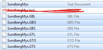
  • I ordered my pcbs from dirtypcbs (it was my first order) and was also quite confused.
    After failing to add the rar-file (I got an error-message about the file format), I only uploaded the .brd-file and that was accepted.
    After your comment sundberg, I am very curious to see how the boards turned out and if they are usable.
    They were shipped on Monday, so it will be a few weeks before they reach me thought.


  • Hardware Contributor

    @BastienVH - Thank you for your input.
    Ok so dirtypcb doesnt accept gerber files but raw eagles .brd files?
    That sounds a bit worrying because the export to those gerberfiles moves some labels and stuff around.
    I have adjusted the .brd so the gerber files are correct and should be used.

    I hope it works out for you! Let us know!
    No answer at this time from dirtypcbs


  • I checked their website again and you should be able to upload de gerber files in a zip-file.
    I uploaded a rar, which was not recognized, I guess.
    After that, I uploaded the board-file and it generated gerberfiles based on that brd-file.
    This is a screenshot of the board generated by dirtypcbs on my order page.
    We'll have to wait and see how they turn out.

    dirtypcbscreenshot.jpg


  • Hardware Contributor

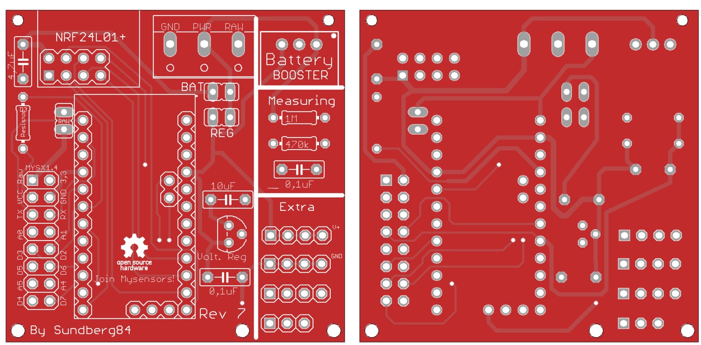
    @BastienVH - It looks right! If the manufacturing process works out the boards are going to be good!


  • Hardware Contributor

    I have uploaded my boards at DirtyPCB in ZIP archives with the GERBER files, so this certainly works. Nice to hear that they also accepted the Eagle .brd file. So far I thought only OSH Park accepted Eagle 7.3 files, so maybe I should just try and see what they make of it.
    @BastienVH @sundberg84 : from the moment DitryPCB shows you a correct PCB image, you can be pretty sure the boards will turn out fine. But as with all lithographic processes, you always need to check the boards for imperfections if you use very dense layouts. In the case of this layout I see no reason to worry about that. And the red board colour is really cool 🙂


  • Hardware Contributor

    I got reply from dirtypcbs.com and in their new page it was possible to upload and sell PCBs.
    I have now uploaded it, and waiting for approval.


  • @GertSanders
    I'll check when they arrive.
    The red is really nice but was actually a mistake, I didn't check the board color setting because I was so excited to order this PCB! 😉
    You get a choice of red, yellow, green, blue, black or white. All without extra cost, which is nice.


  • @sundberg84, Thanks for the simple design.

    Can this board be ordered from dirtypcbs.com? or should we wait until we hear from you?


  • Hardware Contributor

    I have uploaded it to dirtypcbs and waiting for approval.


  • @sundberg84 but i am able to see the board on the dirtypcb's page. Here is the link and it is allowing me to order it. But before i order it i wanted to make sure that there is nothing wrong with this board.

    Thanks for your hardwork.


  • Hardware Contributor

    @ar91 This is not my upload, but it looks right.
    Its not the latest Rev 7 but it Rev6 was working so I think its safe to order.

    If you wait and order from my upload you are also contributing to MySensors as i will donate that small amount that goes to the author when buying.


  • @sundberg84 Sure will wait for your confirmation.


  • Nice job. I will wait as well .


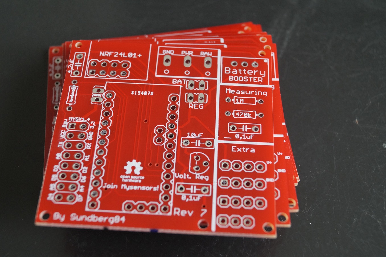
  • I just received my order from Dirtypcbs. The protopack I ordered had 11 boards, so that's nice.
    They took 10 days to arrive in Belgium.
    From first glance, it looks like they's work, but I'll have to test it this weekend to be sure.
    Here's a picture.
    0_1453379527295_DSC06500.jpg


  • Hardware Contributor

    @BastienVH izz naaiss !!!


  • @sundberg84
    I'm waiting your upload with impatience.


  • Hardware Contributor

    @allmp13 sorry, still no answer from dirtypbs - status: waiting for approval
    If you are impatient you can always use the link above... or upload the gerber files.


  • I would share the link to my upload, but I don't want to get in the way of sundberg.
    I think it's better for sundberg to share his link in the top post and donate whatever he makes to the mysensors project (like he said).
    If you can't wait, I'll PM you the link and donate the $1 to mysensors, but it feels wrond to take money (even if I'm giving it away straight afterwards) for something I didn't create myself...


  • @sundberg84, @BastienVH Thanks for your reply


  • Hardware Contributor

    For those who are feeling lucky: http://dirtypcbs.com/view.php?share=16244&accesskey=14b044f08e0126cb42a9dd9522c568e6
    This is my revision 8 and should work just fine but is untested.

    0_1453581853442_1.JPG

    Still no reply from them about my Rev7 upload - and im not expecting it during the weekend so.


  • Nice job thank you!
    This pcb is exactly what I needed to quickly assemble little sensors.
    I was waiting for your v7 upload, but I'm feeling pretty lucky about v8.
    What the mains differences beside making more room for the nrf24 ?


  • Hardware Contributor

    @dark-nico The nrf24 doesnt go outside the PCB so much, and therefore its smaller. But because of that i had to move the 5 to 3.3volt regulator. Nothing else should be different.


  • @sundberg84 Thanks for the quick reply.
    I've ordered a protopack, I'll let you know when I receive/test it.


  • I also just ordered the rev8 board.
    Thanks for sharing, will post my results asap!


  • Looks like chinese new year is coming. On Dirtypcbs site: NEW ORDERS SHIP AFTER FEB. 16TH! IT IS SPRING FESTIVAL, CHINA IS CLOSED. YOU SHOULD KNOW THIS, IT IS THE BIGGEST COUNTRY AND ECONOMY IN THE WORLD, THEY MAKE ALLZ YOUR STUFFS! WE WILL NOT ANSWER ANY EMAILS ABOUT ORDERS PLACED IN THIS PERIOD! NO EXCEPTIONS, NO EMERGENCIES, NO NOTHING. A BIG NOTHING BURGER. GOT IT?!?!


  • @sundberg84 thanks for the nice design!
    I was not really aware of 'official' and 'unofficial' version (and version at all..) so just after the post of ar91 I followed the link to dirtypcbs and ordered 10 Rev6 boards. I will share my experiences here as soon as they arrive and see if it is worth while to order the rev8's. I like it that it is even smaller withour loosing functionality.


  • @sundberg84
    Hey, I've been trying to get my boards to work, but without succes so far.
    They are revision 7 and have mounted 2 boards with a pro mini and the radio but they're not working.
    For the second one I actually checked both the arduino and radio beforehand to see if they functional, which they were.
    Now with them mounted, I still get the "radio init fail" message in the arduino serial monitor.
    The first board, I mounted with the cap, the second one not yet (I ran out of solder wire).

    Any ideas how to troubleshoot this?
    Should I upload some pictures so you can check the solderjob?


  • Hardware Contributor

    Hi @BastienVH

    Do you use 3.3 or 5v arduino?
    How do you power it?
    Did you solder the pinheader / jumper?

    I have rev7 myself, and those works great for me.


  • I have a 3.3v arduino.
    At the moment it's powered the FTDI232 connected to my computer.
    I will transfer to battery once I'm done.
    Do you mean the "BAT" / "REG"?
    I haven't soldered that. I'm guessing that's necessary?

    Also, while I have you hear 😉 , if I want to use the battery measuring, do I have to add the 0.1uF capacitor?
    What advantage does it provide?

    Thanks for your help!


  • Hardware Contributor

    If you use the FTDI connector, make sure its the 3.3v and connect it to Gnd/Pwr on the PCB and not Arduino FDTI connector.
    You could just exclude those pins and connect a battery directly and use that as power and the FDTI as programmer/serial debug only

    Bat or Reg is nessecary!
    See this picture for battery use: https://www.openhardware.io/view/4/EasyNewbie-PCB-for-MySensors
    https://www.openhardware.io/uploads/568ed84b60aa3f8965fbf095/image/3.jpg
    All components in the image is needed (except battery measurment).
    If you dont want to use booster you need to bypass that one with a wire/jumper (or set the jumper on REG instead of BAT but that kills the logic).

    The battery doesnt "need" the 0,1uF but see here:https://www.mysensors.org/build/battery
    "The tap point could be bypassed with a 0.1 uF capacitor to keep the noise level low, at this otherwise high impedance point. "


  • @sundberg84
    Thanks for the explanation!
    I think I've got it now.
    Will test and get back with the results when I've gotten my hands on some more solder wire!


  • Contest Winner

    Hi,
    I see you use CERN OHL but I do not find the required files.
    Where do you store those?
    According to the CERN OHL 1.2 howto, you need to provide the following documentation with your project:
    LICENSE.PDF
    cern_ohl_v_1_2_howto.pdf
    PRODUCT.TXT
    CHANGES.TXT

    Please check the howto closely for how to use the license, or pick another license. If it is not used according to spec, others don't need to follow it either since it is invalid, so you won't be "protected" by it.


  • @BastienVH
    Replying to myself to follow up on my assembly-issues.
    I have been able to get the board to work.
    I don't have my 0.1µF caps yet, so I just put a little blob of solder in the holes so the current could run through.
    Now I've got myself 2 working board. I just have to find a good way to attach my PIR, dallas temp, ... to them.

    Thanks for the work and help!


  • Plugin Developer

    I'am now finnish with my first rev7 node.
    It is a Arduino 5V with DHT-22 and a HC-SR501 sensor.
    1_1454528676795_IMG_6223 copy.jpg
    0_1454528676794_IMG_6224 copy.jpg

    Good work @sundberg84 for the PCB


  • Hardware Contributor

    @BastienVH Good to hear - its not essential to have to 0.1uF cap on the voltage retulator, it will work without but its good to keep noice out.
    @ErrK Nice, I see you run through RAW pin and using the internal voltage regulator on the arduino - I have not tested that much, does it work ok?


  • @sundberg84
    When I get the caps, I'll place them on the board.
    I did notice alot of noise when I was reading battery state on a breadboard in an earlier build, so I will get that sorted.
    Only problem is I can't find them locally, so have to get them from China.
    Will take a while...


  • Plugin Developer

    @sundberg84 yes it's working good. But the problem is that it's eating up the batteries 🙂
    It was up for only 15days.

    I will now test with a arduino that i have removed the led and volt regulator.


  • Hardware Contributor

    Sounds good @ErrK - dont forget to power it through REG and not RAW on the PCB and add a jumper on REG since it wont work if you use the same setup as in the images and remove voltage regulator.


  • Plugin Developer

    Thank you @sundberg84. I will think of that.


  • Hi,
    Why have you redesigned from rev7 to rev8?
    When will the rev8 be tested ?


  • Hardware Contributor

    @Barna - I just wanted to make it smaller, with the radio not sticking out so much.
    I ordered them a while ago, so if they made it out of china before their new year I think it will be tested soon.


  • Just received Rev 8 :

    alt text

    I'll test it asap 😃


  • Hardware Contributor

    Nice. @dark-nico
    The main concern is the new placement of caps and voltage divider - I hope they fit in between the radio and screw terminal. Should not be a problem - but you know, always nice to see it IRL. Might be good to solder them first before radio, arduino and screw terminal.


  • Ok, I'll do that.
    My main problem is that I haven't received both my booster and my 5->3.3 reg. 😞
    So I can test Batt version by bypassing the booster, but it will not tell us if the reg placement is ok.
    I'll dig in my "donor harware" if I can find a reg.


  • Looks good!

    alt text

    and works fine!

    Perfect, thanks again 👍

    I'll test the batt version as soon as I receive the boosters.


  • Hardware Contributor

    @dark-nico - You know its easy to cut the PCB to make it smaller? Using it as 5v you can remove the right battery part:

    Either cut with a knife and brake:
    https://www.youtube.com/watch?v=SiC-_g3iNb8

    Or sometimes i just use a saw (before components are added) - might not be recommended 😉


  • @sundberg84 - Yes I know that I can cut that part, but I think this one will be my test board with all this option, including the battery parts.
    However I'll keep the video method in mind, I was thinking about using a dremel, but, it seems cleaner.


  • Hardware Contributor

    @dark-nico Ok, have not tested adding both Bat and reg/5v posibilities at the same time. Might be that 5v travels backwards towards the booster... try it out, but as I said, not tested.


  • @sundberg84 : I have also received the rev 7 from DirtyPCB and learned how to solder. Very nice and flexible design !
    0_1455455160676_20160214_133450.jpg
    Perfect for a Newbie :). Thnaks a lot for sharing


  • Hardware Contributor

    Hi!
    No problems! Makes me glad to see i made something usefull for others 🙂
    Interesting setup you got the with the HLK as power 👍


  • Great design and project, thank you for sharing it. I really like the rev8 approach in reducing overall size as it will fitt much better in my boxes.
    Is it possible to get rev8 files needed to order PCBs from some other places?
    Keep up the good work!


  • Hardware Contributor

    @dakipro If you "download all project files" @ https://www.openhardware.io/you will get all files (Eagles, Gerber (run with Iteads CAM job) and other stuff).


  • Please excuse the questions, but you did say this is for Newbies, right? 🙂

    I'm planning on using this with the 3.3v Arduino with battery power once things are debugged. I see above that you say to power from the battery input rather than the FTDI pins. Is that for 5V and 3.3V? Also, what is the resistor labeled D3 Res Temp/Hum used for?


  • Hardware Contributor

    Hi! @chuckconnors

    You should input power/gnd to the 5v/GND on the PCB and not the ftdi connector on the arduino you have soldered on the pcb. See the images above. This is how the board is designed. It doesnt matter if its 3.3 or 5v.
    The resistor is for if you want to use for example a dallas temp or dht22 on pin 3, then you can add a resistor there since these sensors require this.


  • @sundberg84 Thanks for the reply. Please forgive my ignorance, but can you explain what happens if you connect power via the FTDI pins? Wouldn't it still power the chip and radio?

    Should I supply the 5V/GND from the FTDI interface to the VCC/GND pads on the bottom left side of the board?


  • Hardware Contributor

    @chuckconnors well it depends on your setup. It can be done with powering through fdti but it's easier to just not recommend it. For example 3.3v with a booster /bat setup powering through vcc on arduino will not power the radio.

    That works great. You can connect the fdti to the arduino but extend vcc and gnd with wired to the pcb. To power everything run these cables to the pads in the middle and top of the pcb.


  • @sundberg84 Thanks for the clarification. I took a look at the board images and I see what you mean. Forgive me again for trying your patience, but could you be so kind as to tell me what the minimum required components are for using this board with a 3.3V Arduino?

    Currently I'm only using the Arduino, radio, radio capacitor, power supply (battery or 5V ), and whatever sensors required for that node. This worked out well using the standard hookups as the radio was being powered by the Arduino and the radio is guaranteed the correct voltage via the built in regular on the Arduino, but as you've mentioned this isn't an option with your board. Do I need to include the battery caps and regulator? Again, I'm a novice and I can follow the traces on the top side of the board using the silkscreen labels as a guide but it's a bit harder to follow on the unlabeled bottom side. Do most of you guys use the 5V Arduino?


  • @sundberg84 said:

    If you use the FTDI connector, make sure its the 3.3v and connect it to Gnd/Pwr on the PCB and not Arduino FDTI connector.
    You could just exclude those pins and connect a battery directly and use that as power and the FDTI as programmer/serial debug only

    Bat or Reg is nessecary!
    See this picture for battery use: https://www.openhardware.io/view/4/EasyNewbie-PCB-for-MySensors
    https://www.openhardware.io/uploads/568ed84b60aa3f8965fbf095/image/3.jpg
    All components in the image is needed (except battery measurment).
    If you dont want to use booster you need to bypass that one with a wire/jumper (or set the jumper on REG instead of BAT but that kills the logic).

    The battery doesnt "need" the 0,1uF but see here:https://www.mysensors.org/build/battery
    "The tap point could be bypassed with a 0.1 uF capacitor to keep the noise level low, at this otherwise high impedance point. "


  • Hardware Contributor

    @chuckconnors Well, it is possible... you can always hard wire/bypass stuff with wires... its possible.
    See @BastienVH for minimun req. 3.3v. In bat. operations you feed the radio directly from batteries - less noice and radio can handle down to 0.9V (i think) so its not a problem. You need the booster for sensors and arduino requiers 3.3v to run. You can also feed 3.3v directly to VCC on the PCB if you have that regulated. Then you can just add jumper to reg.

    If you tell me exactly what you want to do i can help you and explain what you need and how to wire it. With your setup now like you described and you run that on 3v batteries it will be dead within a week.

    If you want battery power - you should go with 3.3v arduino (advantage: last longer)
    If you have regulated 5v (like from a phone charger) use 5v arduino (advantage: smaller PCB)


  • Hardware Contributor

    First battery node with rev 8 is up and running... need to test 5v version as well but looks good so far
    0_1456177952831_20160222_213338.jpg


  • Hi,
    I've received boards from dirtypcb, it looks pretty good! Very nice design!

    Just have a few questions:

    1. May I use 78L33 voltage regulator instead of LE33ACZ?
    2. Do you know what is the RAW input tollerance of Pro Mini 3.3V (ebay one, not genuine one)?
      I'm thinking of attach temperature sensor to my PIRs in my home and feed it parasitically from PIR (~13VDC). Do you think is it possible?

  • Hardware Contributor

    Hi Lukasz!

    1. 78L33 is a 3.3v regulator so yes, but is different pins depending on which version you have so you need to check where you put the pins. From left Vout, Gnd and Vin should be connected to the PCB. Compare it with LE33 pinouts.

    2. In theory it should be 12v BUT its a fact that manu clones cant handle that. I would not go above 9v.


  • @sundberg84

    1. Ok I will check pinouts
    2. I understand. So what is the best way in your opinion to feed node parasitically in safe manner? Use voltage regulator to step down voltage to safe 3.3v? Should I expect any significant heat? I'm aware of heat becouse it can trigger false alarm of my PIR

  • Hardware Contributor

    I would go with a voltage regulator from your 13v to 5 or 3.3v depending on which arduino you buy. I would connect this to PWR on the pcb and avoid using arduino internal voltage regulator (avoid use of two voltage regulators).


  • Thanks sundberg84, I will give a try.
    One last question. I didn't find any note in BOM list. May I use ceramic caps instead of electrolitic ones?
    I 'm not able to find electrolitic 0.1uF caps at my local store.


  • Hardware Contributor

    Yes, you can replace it with a ceramic. There are alot to read about the differences on the net.


  • Ger..
    Like to order your stuff...
    Only what are the specs of all your Resistor and Capacitor..
    Or perhaps you can make the bom complete..

    Cannot wait...


  • Hardware Contributor

    @Dombo71 - Hi!
    The BOM is complete, all capacitors needed and its values are found in the BOM tab.
    Since caps are so cheap and common i wont specify any link since you can find theme anywhere.


  • Anyone from the Netherlands who ordered a pack of the rev.8 boards? How long did it take to be delivered?
    The status update on dirtypcbs.com says Shipped on 27 Jan 2016 and I can't wait until I receive them! 🙂


  • Hero Member

    @lxz I can take around 2 months... ;-(, but in most cases within 5 weeks after shipping.


  • By heart it took about 10-12 days. "maar pin me er niet op vast"


  • Hardware Contributor

    @lxz Chinese New Year Holiday is just over, there seems to be quite a backlog for items ordered in january. It depends on some luck, to Antwerpen took around 6 weeks.


  • Thanks for the replies, guess I have to wait some more then 🙂


  • I love this PCB. It makes things so much easier. I am having a little problem with the battery version though. I think I've got it wired up right. I've got the jumper. I've got the booster. But, when I plug in a battery (I've tried a 3.7 volt battery, outputting 3.3v - the one from the solar weather station project, and 2 or 4 AA batteries), I get a "Radio Init Fail" message in the serial monitor. Also, the LED at the back, the one near the reset button, does not light brightly. It initially flashes brightly, then nothing.

    I've wired it up two different times for the battery setup, and with neither am I getting the live radio.

    I am able to get a good radio with the 5v setup.

    0_1457023603222_IMG_2712 (1).JPG 0_1457023616266_IMG_2713 (1).JPG


  • Hardware Contributor

    Hi!
    @gentrfam
    It looks correctly wired. The radio (when bat jumper is selected) is feed directly from the battery, so you need to keep within the specs of the radio (0,9v- 3.6v).
    First thing I would do is measure volt over radio. Also measure volt over the arduino. Working backwards can give you a clue where it fails if its a power problem.

    My wild guess is that either its not a genuine/working NRF radio, or you have a cold/bad solder point on arduino and/or radio.

    I always check my radio before soldering them... a while back I counted that I have ordered 33 radios from Ebay and 3 of them was broken so far. So i have a Easy board just for radiocheck loaded with timeaware sketch.


  • @sundberg84 Thank you. I checked, and out of the solar-powered battery, I'm actually just out of the radio spec - 3.7-4.0v. I'm going to try with a new radio, and a smaller battery to see if I fried this radio.

    In the meantime, I tried to run the battery through an LE33 regulator on a breadboard. (Eventually, I'd like to run the solar-battery through the measuring circuitry on the PCB.) Any idea why the LE33 would be outputting 0.6v?

    Thanks for your help. I'm afraid I'm a complete and total noob on this.


  • Hardware Contributor

    No, check incoming voltage to the LE33 - is this correct?
    Is the caps oriented (ground) correcly? (if you have any).
    Broken?


  • Hi,
    I already received PCB, soldered everything and I'm stuck with reliable radio quality. It works good only when I keep touching antenna on nrf board with my finger. Once I release my finger I've got st=fail.
    I've soldered two boards already, tried with two different radios and have same results
    I use nrf24L01+ with internal antenna and 5v pro mini, voltage regulator and caps (100nF, 10uF and 4,7uF) as well.

    Do you have any ideas what can be wrong?
    0_1457048331343_2016-03-04 00.34.16.jpg
    0_1457048341100_2016-03-04 00.34.32.jpg


  • I can't wait to get mine, I bet on version 8 😄 .Fear {display:none;} despite being a noob with electronics.

    Although I do have a question, for a 5v pro mini...

    Suppose I power this using a 9v battery, assuming connection to the RAW, that means not BAT or REG jumpers ?

    And I also wont be able to use the voltage divider to read the voltage.

    However It looks like that if there is no jumper in BAT or REG the voltage divider circuit is independent. Would it be possible to re-wire the voltage divider circuit to measure the RAW 9v from the battery?

    Does anyone know what happens to the internal voltage regulator when the battery gets week? Would the vcc library get any idea of what is happening to the current internally?

    Cheers


  • Hello!
    @fisher
    Please have a look here: http://forum.mysensors.org/topic/2989/nrf24l01-range-of-only-few-meters/7
    It solves my problems.


  • Hardware Contributor

    @fisher as @sven said - it might be a issue with your nrf... i have seen this issues in several forum posts.
    Also, you can try to add a wire from nrf ground to scource ground (and/or try same from voltage regulator) to strengthen your ground connection.

    @barduino Asuming you are using 5v arduino and using RAW you add a voltage regulator (3.3v) to the radio. You do not need any jumper.
    The voltage divider only works from PWR input but if you make a wire from PWR to Vin (right hole) on the booster this should work fine with the voltage divier.

    The internal voltage regulator can handle 3.35 -12 V (3.3V model) or 5 - 12 V (5V model). Below this the regulator will fail, so you need to set your battery measurment to 0 % 5v 100% = 9v.

    This has not been tested by me yet on rev 8 so please share your findings.


  • @sven, @sundberg84 I soldered 83mm wire as mentioned on video and it works like a charm. I'm wondering if it's poor quality of my piece of radios or maybe this is general problem with this type of radio.

    Guys thanks again. You made my day!


  • Thanks @sundberg84


  • It took a while, but I received the rev8 boards last week. I have already had some time to play with it and it works perfectly on 2x AA. Thanks for sharing your pcb design @sundberg84


  • @sundberg84 said:

    @chuckconnors Well, it is possible... you can always hard wire/bypass stuff with wires... its possible.
    See @BastienVH for minimun req. 3.3v. In bat. operations you feed the radio directly from batteries - less noice and radio can handle down to 0.9V (i think) so its not a problem. You need the booster for sensors and arduino requiers 3.3v to run. You can also feed 3.3v directly to VCC on the PCB if you have that regulated. Then you can just add jumper to reg.

    If you tell me exactly what you want to do i can help you and explain what you need and how to wire it. With your setup now like you described and you run that on 3v batteries it will be dead within a week.

    If you want battery power - you should go with 3.3v arduino (advantage: last longer)
    If you have regulated 5v (like from a phone charger) use 5v arduino (advantage: smaller PCB)

    @sundberg84 I just got my boards in and am hoping to hook things up this weekend for a simple Temp/Humidity node with a DHT11. The plan is to provide 5V input from an old phone charger. I'd like to wire this directly to the arduino via the GND PWR pads at the top. What jumper do I need to set for this?

    Can I just power the radio through the 4.7uF cap via the 3.3V and ground pads on the left side of the board via some wires? Does the radio already have a ground coming from the ground on the arduino? I'm assuming that power would be coming from the arduino regulator. Will this set up work?

    Thanks again for your patience.


  • Hardware Contributor

    @chuckconnors - great weekends plan 👍
    Im suspecting you are going to run a 3.3v pro mini?

    The PCB is designed so if you want to input 5v you set the REG jumper, use a 5v pro mini and use a external voltage regulator for the radio - see here!

    If you are planning to use a 3.3v arduino and power it with 5v you need to input power to RAW and wire a connection/bypass on the voltage regulator. This is not the main design for the PCB but should work. What you need to know is that pro mini internal voltage regulator is not as good as an LE33AC in my world so there might still be great value of using the 0.1 and 10uF caps on power to radio.

    Ground from Radio always goes straight to ground scource, not Arduino Pro mini.


  • @sundberg84 Thanks for the information. So the 5V source goes to RAW input and this goes to the RAW jumper on the left portion of the board. I need to jump that to complete the connection to get RAW power to the Arduino, right? From there it looks like the 3.3V connects to the 4.7uF cap and the power on the radio so I'm assuming once RAW power is supplied to the Arduino that I'd start getting 3.3V output from the 3.3V pin on the Arduino. Am I reading the traces wrong?

    Thanks again


  • Hardware Contributor

    @chuckconnors Hi! Dont mind the RAW jumper, this is a future/requirement for MysX connector and is only used if you want RAW power to the connector to the left. Put 5v to the top right RAW input.

    0_1458150780563_1.jpg

    The caps are not regulating anything - they are just smoothing everything out 🙂


  • @sundberg84 A picture is worth a 1000 words! Thanks for taking the time to do this for me. I don't have the 0.1uF or 10uF caps available but will order and add them. My real problem is that I am limited in the components I have on hand and have to order them so it takes a while (plus I'm anxious to work on this!).


  • Hardware Contributor

    @chuckconnors You can do it without the 0.1 and 10uF caps but it can generate some range issues and instability. The most important is 4.7 but I have nodes both working without 0.1 and 10uFcaps and nodes that completley failed without them.


  • I am doing the above (RAW with 5-7V on 3v minis). Would be great in a future revision to allow the bypass of the regulator. Also I jumped RAW to PWR and cut the trace from PWR so I could use a 2 pin header for power and ground 🙂


  • Hardware Contributor

    @chuckconnors I will think about how to bypass the voltage regulator, but anyway you need to solder something (either a jumper or voltage regulator). Do you have any tips?

    Good tip with the raw/pwr. If you have not cut the pcb you also have the proto area where the first is VCC (3.3) and second is Gnd.


  • @sundberg84 I was able to use your marked up image to successfully build two nodes without problem. Thanks again for the help with hooking things up and for providing the board for purchase as well. I was able to build the whole thing in about 10 minutes even with my limited soldering abilities.

    The only gripe I have is that one of my boards had a hole for the 4.7uF cap that wasn't completely drilled out. It was easy enough to just solder to the nearby ground. This is a dirtyboards quality control issue. I'm hoping not to see this on any of my other boards. I guess I'll have to inspect them before adding the components for future nodes.

    All the best to you!


  • Hardware Contributor

    @chuckconnors! Thank you for those kind words - it is appreciated.
    To save your node without the hole for 4.7uF you can solder it directly on the nrf if needed. I hope you have great use for the boards in the future.


  • @sundberg84 I'm about to make an aliexpress order and would like to get some voltage regulators. I scanned through the post but didn't see a BoM. Can you please tell me the part number for the voltage regulator used?


  • Hardware Contributor


  • The boards have arrived!!! YES!!

    It took about 3 weeks between the shipping status and my mailbox. I guess I cant complain.

    0_1459186281454_IMG_0422.JPG

    @sundberg84 I do have another question.

    Are the pins A6, A7 and the extra ground (next to A6) connected at all? is it worth to solder a connector on them to the PCB?

    Edit: or maybe 2...
    D8 does not seem to be used, is this correct?

    Cheers


Suggested Topics

0
Online

11.2k
Users

11.1k
Topics

112.5k
Posts