💬 Sensebender Gateway
-
@tbowmo More practical question. I have received the GW and it already has MySensors 2.1.0 software. Excellent service by Itead. Can you please help me how to map LEDs in the GW sketch? I can see that they are connected to pins 38, 41, 42, 39, 40 as LED1, LED2, LED3, LED4 and LED5. Thanks
you should be able to use LED_BLUE, LED_GREEN etc. defines (or even just LED_1, LED_2..) in your sketch, to access the different LED's on board the gateway. That is, if you are using the SenseBender GW hardware support files in arduino (installation instructions are here https://github.com/mysensors/ArduinoBoards)
Also, look at the board definition files, located here https://github.com/mysensors/ArduinoHwSAMD/blob/master/variants/mysensors_gw/variant.cpp
and here https://github.com/mysensors/ArduinoHwSAMD/blob/master/variants/mysensors_gw/variant.h -
You might be able to compile with the standard arduino zero BSP files. But the IO mapping is not the same at all.. I have swapped some pins to make routing a bit easier. Also the SPI channels are configured a bit differently than the standard arduino, if I remember right. So I will advise to use the mysensors gateway BSP files..
-
No, platformio is still on my bucketlist.. There is just not hours enough for everything :)
-
Has anyone designed a case for the sensebender gateway ?
-
Has anyone designed a case for the sensebender gateway ?
-
Tea time..
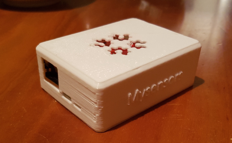
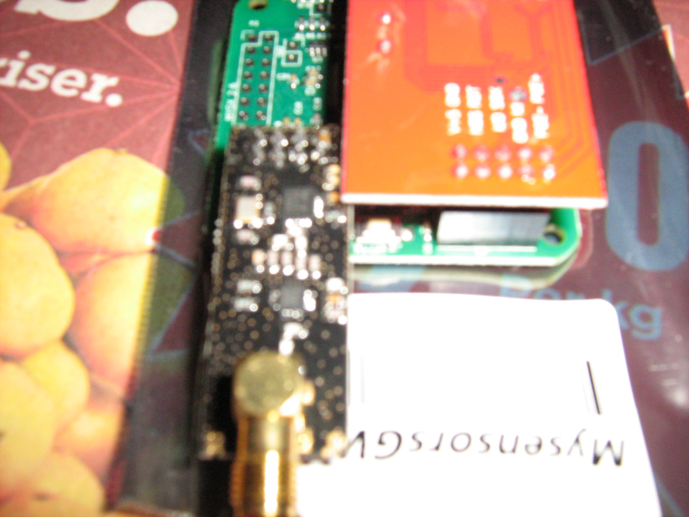
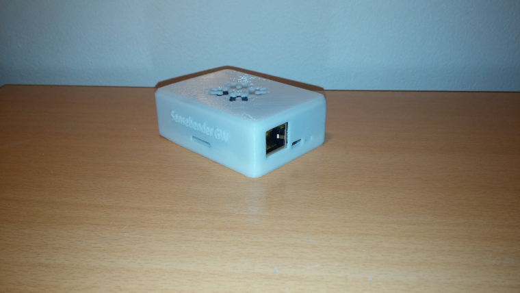
Here is my custom box for your RFM69 Sensebender GW ! Beautiful board though ;)
No nail no screw :)
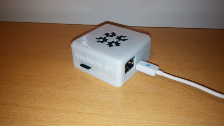
Last final minor check and i release the files, sure! (i've done one for nrf too in case..)
-
Tea time..
Here is my custom box for your RFM69 Sensebender GW ! Beautiful board though ;)
No nail no screw :)
Last final minor check and i release the files, sure! (i've done one for nrf too in case..)
@scalz beautiful box!!!
Looking forward to print it too as soon as you publish it, but mine will be with nrf24l01+. Having been running both networks, I'm so much in favour of rfm69. It just works. No more caps to stabilise power or any other rf issues.I have decided to use Moteino Mega with a built-in antenna as rfm69 gateway though - it is very small and goes inside into an RPi box. And has got more memory than atmega328p
-
Tea time..
Here is my custom box for your RFM69 Sensebender GW ! Beautiful board though ;)
No nail no screw :)
Last final minor check and i release the files, sure! (i've done one for nrf too in case..)
-
Little gift.. :)
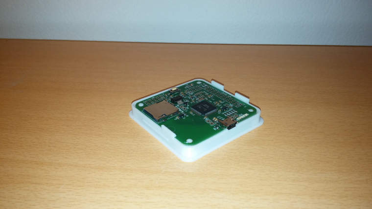
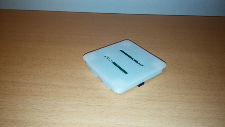
Custom box for the NRF non PA version:
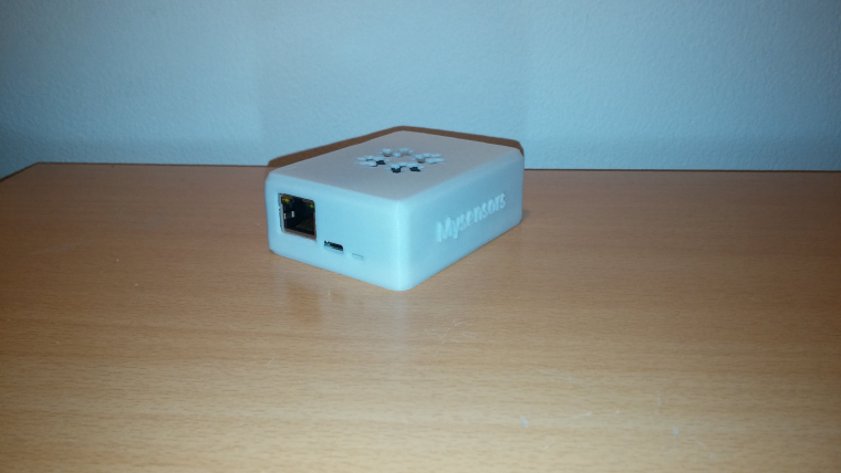
A bit enlarged for NRF.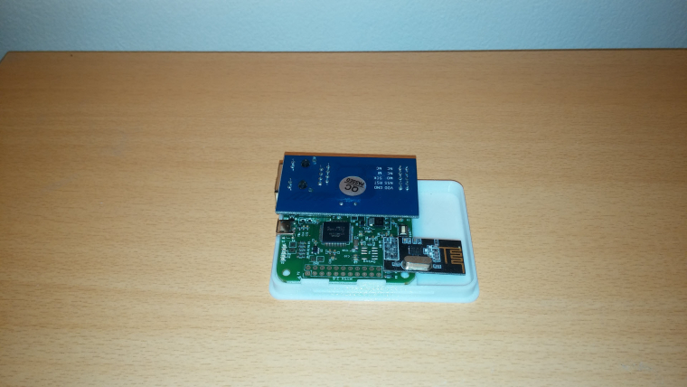
And here the 3d preview for both versions with my little cheat for bicolor as i've still not added this feature to my printer
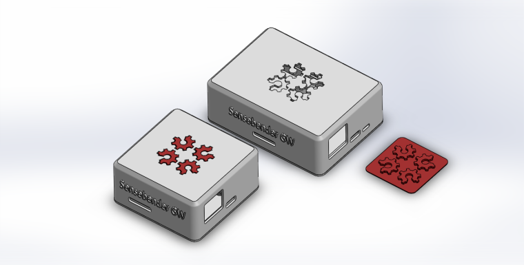
You can see i've added a little slot near usb on the NRF version, it's for the leds indication in case box wouldn't be white (no need for white box, you can see it by transparency). I'll do the same for rfm69, and put variant stl with it or not.Next Nrf PA version, and that'll be fine ;)
-
@alexsh1 why, i don't understand :stuck_out_tongue_winking_eye:
Here it is : http://www.thingiverse.com/thing:2084269
-
I'm proud to say enclosure files have been integrated in the MySensors Sensebender GW project and git.
So you can find the files here at Mysensors.Enjoy :)
-
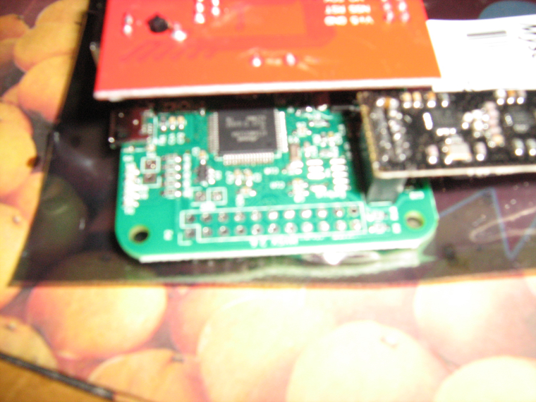
Yes, according to the build instructions here, you can also raise the socket a bit over the pcb.
The problem is that the ethernet connector is higher than a normal IDC socket, which means you can't insert the board fully in the socket. I have searched for a higher variant of the socket, but haven't found a suitable candidate..
-
Yes, according to the build instructions here, you can also raise the socket a bit over the pcb.
The problem is that the ethernet connector is higher than a normal IDC socket, which means you can't insert the board fully in the socket. I have searched for a higher variant of the socket, but haven't found a suitable candidate..